EP2836690B1 - Zündkerze mit neben- und hauptbrennraum - Google Patents
Zündkerze mit neben- und hauptbrennraum Download PDFInfo
- Publication number
- EP2836690B1 EP2836690B1 EP14734707.4A EP14734707A EP2836690B1 EP 2836690 B1 EP2836690 B1 EP 2836690B1 EP 14734707 A EP14734707 A EP 14734707A EP 2836690 B1 EP2836690 B1 EP 2836690B1
- Authority
- EP
- European Patent Office
- Prior art keywords
- flow
- enclosure
- ignition
- fuel mixture
- air
- Prior art date
- Legal status (The legal status is an assumption and is not a legal conclusion. Google has not performed a legal analysis and makes no representation as to the accuracy of the status listed.)
- Active
Links
- 238000002485 combustion reaction Methods 0.000 claims description 93
- 239000000446 fuel Substances 0.000 claims description 84
- 239000000203 mixture Substances 0.000 claims description 72
- 230000000977 initiatory effect Effects 0.000 claims description 38
- 230000002093 peripheral effect Effects 0.000 claims description 13
- 238000000034 method Methods 0.000 claims description 6
- 239000012530 fluid Substances 0.000 claims description 4
- 230000007704 transition Effects 0.000 description 3
- 230000000903 blocking effect Effects 0.000 description 2
- VNWKTOKETHGBQD-UHFFFAOYSA-N methane Chemical compound C VNWKTOKETHGBQD-UHFFFAOYSA-N 0.000 description 2
- 238000010926 purge Methods 0.000 description 2
- 230000009471 action Effects 0.000 description 1
- 230000004323 axial length Effects 0.000 description 1
- 230000008901 benefit Effects 0.000 description 1
- 230000000295 complement effect Effects 0.000 description 1
- 230000006835 compression Effects 0.000 description 1
- 238000007906 compression Methods 0.000 description 1
- 230000003111 delayed effect Effects 0.000 description 1
- 238000005474 detonation Methods 0.000 description 1
- 230000003628 erosive effect Effects 0.000 description 1
- 238000002347 injection Methods 0.000 description 1
- 239000007924 injection Substances 0.000 description 1
- 239000012212 insulator Substances 0.000 description 1
- 238000004519 manufacturing process Methods 0.000 description 1
- 238000012986 modification Methods 0.000 description 1
- 230000004048 modification Effects 0.000 description 1
- 239000003345 natural gas Substances 0.000 description 1
- 230000003647 oxidation Effects 0.000 description 1
- 238000007254 oxidation reaction Methods 0.000 description 1
- 230000001590 oxidative effect Effects 0.000 description 1
- 230000008569 process Effects 0.000 description 1
- 230000001737 promoting effect Effects 0.000 description 1
- 230000000171 quenching effect Effects 0.000 description 1
- 238000000926 separation method Methods 0.000 description 1
Images






Classifications
-
- F—MECHANICAL ENGINEERING; LIGHTING; HEATING; WEAPONS; BLASTING
- F02—COMBUSTION ENGINES; HOT-GAS OR COMBUSTION-PRODUCT ENGINE PLANTS
- F02P—IGNITION, OTHER THAN COMPRESSION IGNITION, FOR INTERNAL-COMBUSTION ENGINES; TESTING OF IGNITION TIMING IN COMPRESSION-IGNITION ENGINES
- F02P13/00—Sparking plugs structurally combined with other parts of internal-combustion engines
-
- F—MECHANICAL ENGINEERING; LIGHTING; HEATING; WEAPONS; BLASTING
- F02—COMBUSTION ENGINES; HOT-GAS OR COMBUSTION-PRODUCT ENGINE PLANTS
- F02B—INTERNAL-COMBUSTION PISTON ENGINES; COMBUSTION ENGINES IN GENERAL
- F02B19/00—Engines characterised by precombustion chambers
- F02B19/10—Engines characterised by precombustion chambers with fuel introduced partly into pre-combustion chamber, and partly into cylinder
- F02B19/1019—Engines characterised by precombustion chambers with fuel introduced partly into pre-combustion chamber, and partly into cylinder with only one pre-combustion chamber
- F02B19/108—Engines characterised by precombustion chambers with fuel introduced partly into pre-combustion chamber, and partly into cylinder with only one pre-combustion chamber with fuel injection at least into pre-combustion chamber, i.e. injector mounted directly in the pre-combustion chamber
-
- F—MECHANICAL ENGINEERING; LIGHTING; HEATING; WEAPONS; BLASTING
- F02—COMBUSTION ENGINES; HOT-GAS OR COMBUSTION-PRODUCT ENGINE PLANTS
- F02B—INTERNAL-COMBUSTION PISTON ENGINES; COMBUSTION ENGINES IN GENERAL
- F02B19/00—Engines characterised by precombustion chambers
- F02B19/10—Engines characterised by precombustion chambers with fuel introduced partly into pre-combustion chamber, and partly into cylinder
- F02B19/1095—Engines characterised by precombustion chambers with fuel introduced partly into pre-combustion chamber, and partly into cylinder with more than one pre-combustion chamber (a stepped form of the main combustion chamber above the piston is to be considered as a pre-combustion chamber if this stepped portion is not a squish area)
-
- F—MECHANICAL ENGINEERING; LIGHTING; HEATING; WEAPONS; BLASTING
- F02—COMBUSTION ENGINES; HOT-GAS OR COMBUSTION-PRODUCT ENGINE PLANTS
- F02B—INTERNAL-COMBUSTION PISTON ENGINES; COMBUSTION ENGINES IN GENERAL
- F02B19/00—Engines characterised by precombustion chambers
- F02B19/12—Engines characterised by precombustion chambers with positive ignition
-
- F—MECHANICAL ENGINEERING; LIGHTING; HEATING; WEAPONS; BLASTING
- F02—COMBUSTION ENGINES; HOT-GAS OR COMBUSTION-PRODUCT ENGINE PLANTS
- F02B—INTERNAL-COMBUSTION PISTON ENGINES; COMBUSTION ENGINES IN GENERAL
- F02B19/00—Engines characterised by precombustion chambers
- F02B19/16—Chamber shapes or constructions not specific to sub-groups F02B19/02 - F02B19/10
- F02B19/18—Transfer passages between chamber and cylinder
-
- H—ELECTRICITY
- H01—ELECTRIC ELEMENTS
- H01T—SPARK GAPS; OVERVOLTAGE ARRESTERS USING SPARK GAPS; SPARKING PLUGS; CORONA DEVICES; GENERATING IONS TO BE INTRODUCED INTO NON-ENCLOSED GASES
- H01T13/00—Sparking plugs
- H01T13/54—Sparking plugs having electrodes arranged in a partly-enclosed ignition chamber
-
- Y—GENERAL TAGGING OF NEW TECHNOLOGICAL DEVELOPMENTS; GENERAL TAGGING OF CROSS-SECTIONAL TECHNOLOGIES SPANNING OVER SEVERAL SECTIONS OF THE IPC; TECHNICAL SUBJECTS COVERED BY FORMER USPC CROSS-REFERENCE ART COLLECTIONS [XRACs] AND DIGESTS
- Y02—TECHNOLOGIES OR APPLICATIONS FOR MITIGATION OR ADAPTATION AGAINST CLIMATE CHANGE
- Y02T—CLIMATE CHANGE MITIGATION TECHNOLOGIES RELATED TO TRANSPORTATION
- Y02T10/00—Road transport of goods or passengers
- Y02T10/10—Internal combustion engine [ICE] based vehicles
- Y02T10/12—Improving ICE efficiencies
Definitions
- lean fuel mixture is a mixture of air and fuel containing excess air beyond that which is stoichiometric for combustion.
- the lean fuel mixture often results in poor combustion such as misfires, incomplete combustion and poor fuel economy.
- Efforts to improve combustion result in detonation or the use of high energy spark which leads to short spark plug life.
- One factor that can lead to such events is the poor ability of conventional spark plugs to effectively and consistently ignite a lean fuel mixture in the cylinder of the operating engine.
- DE3120007 (A1 ) describes an internal combustion engine has at least one main combustion chamber, a secondary combustion chamber connected to the latter by way of a transfer port, which secondary chamber is of rotationally symmetrical design and a spark plug projecting into one end of the secondary combustion chamber, with electrodes and an ignition chamber enclosing these electrodes, which has at least one ignition chamber orifice opening into one end of the secondary combustion chamber.
- the transfer port is arranged at the other end of the secondary combustion chamber so that a fuel-air mixture flowing in from the main combustion chamber strikes the spark plug in the form of a jet.
- the jet is strongly deflected by the spark plug within a zone, which is only slightly greater than the cross-section of the jet.
- the concepts herein relate to igniting an air/fuel mixture in a combustion chamber of an engine using an antechamber.
- FIG. 1 shows a cross-section of a portion of an example internal combustion engine 100.
- the example internal combustion engine 100 is a reciprocating engine and includes a head 102, a block 122, and a piston 104.
- the piston 104 is located inside a cylinder inside the block 122.
- the piston 104 is able to reciprocate inside the cylinder during engine operation.
- the combustion chamber 106 is a volume located inside the cylinder between the head 102 and the piston 104, and is bounded by the block 122.
- the example internal combustion engine 100 includes an intake passage 108 with intake valve 110 and an exhaust passage 112 with exhaust valve 114.
- the passages 108, 112 are in the head 102 adjacent to the combustion chamber 106, and the valves 110, 114 form part of the walls of the combustion chamber 106.
- the intake valve 110 opens to let a fresh charge of air/fuel mixture flow from the intake passage 108 into the combustion chamber 106.
- the intake valve 110 admits only air and an in-combustion chamber fuel injector admits fuel to form the air/fuel mixture in the combustion chamber 106.
- the exhaust valve 114 opens to exhaust combustion residuals out of the combustion chamber 106 and into the exhaust passage 112.
- the example internal combustion engine 100 includes an example igniter plug carrier 116 housing and an igniter plug 124.
- the igniter plug carrier 116 is a tubular housing located in the head 102 and is threadingly and/or otherwise coupled to the head 102. In some instances, the igniter plug carrier 116 can extend into the combustion chamber 106, be flush with a wall of combustion chamber 106, or be recessed from a wall of combustion chamber 106.
- the example igniter plug 124 is received inside the example igniter plug carrier 116 and is coupled to the carrier threadingly and/or otherwise.
- the carrier 116 thus defines an outer enclosure around the igniter plug 124.
- the antechamber 120 is an outer chamber inside the carrier 116 adjacent to but separate from the combustion chamber 106. In some instances, the antechamber 120 can be formed in the head 102 itself and the carrier 116 can be omitted. The antechamber 120 is also adjacent to but separate from the interior of the igniter plug 124. In other instances, rather than being in a separate carrier, the antechamber 120 can be integrated with the igniter plug 124 (e.g., in a common or conjoined housing or enclosure). The antechamber 120 is shown having a symmetrical shape about the centerline of the carrier 116 and igniter plug 124, but in other instances it could be an asymmetrical shape.
- the antechamber 120 is shown having a largest transverse interior dimension (e.g., diameter) that is larger than the largest transverse interior dimension of igniter plug 124 and shell.
- the antechamber 120 also has larger interior volume than the fluid containing volume of the plug 124. In certain instances, the antechamber 120 can be 10, 20 or even 30 times the volume of the fluid containing volume of the plug 124.
- the example igniter plug carrier 116 includes openings 118.
- the openings 118 include external ends which terminate at the exterior of the carrier 116 and are nominally located inside the combustion chamber 106.
- the internal ends of the openings 118 converge to a central passage 126 that opens into the antechamber 120.
- the openings 118 can number one or more and can be located on the carrier 116 in a symmetric or asymmetric pattern, diverging from the central passage 126.
- the openings 118 allow charge, flame, and residuals to flow between the antechamber 120 and the combustion chamber 106.
- the openings 118 and central passage 126 operate as jet passages to nozzle combusting air/fuel mixture from the antechamber 120 into divergent flame jets that reach deep into the combustion chamber 106 and ignite the charge in the combustion chamber 106.
- the openings 118 and central passage 126 also nozzle fresh air/fuel mixture from the combustion chamber 106 into the plug 124.
- the central passage 126 nozzles the flow into a consolidated flow along the center of the antechamber 120 directed primarily toward the igniter plug 124.
- the igniter plug 124 is a device configured to initiate a flame kernel to ignite the charge in the combustion chamber, such as a spark plug, hot surface igniter, laser igniter, and/or other type of igniter.
- the plug 124 of FIG. 1 is a "prechamber" type plug in that it includes an enclosure that defines an inner chamber enclosing the location of flame kernel initiation. This enclosure is, itself, enclosed within the antechamber 120, and thus an inner enclosure.
- the igniter plug 124 can be other configurations, including an open ended plug.
- the spark surface may be recessed within the igniter plug cavity with or without a flow restricting end cap or be extended into the antechamber 120.
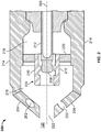
- FIG. 2 illustrates a cross-sectional view of an example igniter plug 200 that can be used as plug 124. Other configurations of igniter plugs can be used.
- the example igniter plug 200 is elongate and centered around a longitudinal central axis 206.
- the central ignition body 208 extends along the longitudinal axis 206 and further extends from a plug body or base 212.
- the second ignition body 210 is tubular and is disposed inside a shell 214.
- the base 212 is an insulator and the center ignition body 208 and the second ignition body 210 are two electrodes that form a spark gap (i.e., an ignition gap where ignition initiates) at the narrowest point between the bodies.
- the igniter plug is a heated surface igniter
- one or both of the center ignition body 208 and the second ignition body 210 are heated surfaces for initiating a flame kernel in the gap between the bodies.
- the tubular ignition body 210 surrounds the center ignition body 208 and has a tubular portion that extends axially forward beyond the end of center ignition body 208. This tubular portion forms a velocity control tube 224.
- the velocity control tube 224 is a tubular structure that, in FIG. 2 , is shown extending beyond the end of the center ignition body 208.
- the velocity control tube 224 is configured to collect and direct flow into a flame kernel initiation gap (e.g., spark gap) between the center ignition body 208 and the tubular ignition body 210.
- the velocity control tube 224 and tubular ignition body 210 can be cylindrical, polygonal, or some other shape.
- the center ignition body 208 similarly has a cylindrical shape, a polygonal shape, or some other shape.
- the ignition bodies can also have a variable shape along their axial length.
- the tubular ignition body 210 and center ignition body 208 may or may not be the same or corresponding shape.
- the velocity control tube 224 and tubular ignition body 210 are both shown as being continuous without breaks, they need not be without breaks.
- the tubular ignition body 210 can be formed of multiple ground electrodes that converge around the center ignition body 208 but do not contact and form a generally tubular shape.
- Other arrangements of ignition bodies i.e., other than a tubular ignition body surrounding a central ignition body
- the ignition body (whether tubular, J-shaped or otherwise) can be provided with or without the velocity control tube 224.
- the plug 200 includes a shell 214 that is a portion of the enclosure.
- the shell 214 defines a prechamber of the plug 200 that is a fluid containing volume containing a forward zone 218 in front of the flame kernel initiation gap and a back zone 216 behind the flame kernel initiation gap.
- the shell 214 is attached to the base 212 and holds an end cap 204, or a nozzle, but, as described below, may also function without an end cap 204.
- An end cap 204 constitutes another portion of the enclosure and a front end of the forward zone 218 of the igniter plug 200. In certain instances, the end cap 204 can be integrated into the shell 214 (formed as a single piece), as opposed to being a separate piece attached to the shell 214 as is shown.
- the shell 214 and end cap 204 define a male conical shape that protrudes into the antechamber 120 to facilitate recirculation within the antechamber 120 (discussed below).
- the end cap 204 can be flat, have a domed shape, or have another shape.
- the end cap 204 has a center opening 222 and a plurality of peripheral openings 202.
- the center opening 222 is configured to direct flow incoming into the forward zone 218 primarily towards and into the interior of the velocity control tube 224 and into the flame kernel initiation gap.
- the peripheral openings 202 are peripheral jet passages configured to direct flow incoming into the prechamber primarily to an exterior of the tubular ignition body 210 and to swirl around the prechamber.
- the center opening 222 is axially oriented and aligned with the longitudinal axis 206, and the peripheral openings are neither parallel nor perpendicular to the longitudinal axis 206.
- Each of the peripheral openings 202 can be the same size (i.e., have the same cross-sectional flow area) or they can be different sizes.
- the center opening 222 can, likewise, be the same size as the peripheral openings 202 or of a different size.
- the openings 202, 222 operate as jet passages that nozzle combusting air/fuel mixture from the prechamber into flame jets that reach deep into the antechamber 120 and ignite the charge in the antechamber 120.
- the openings 202, 222 Prior to ignition, operate as jet passages that nozzle fresh air/fuel mixture from the antechamber 120 into jets into the prechamber.
- the tubular ignition body 210 is shown supported from a disk portion 220 mounted to the interior sidewall of the shell 214. In other instances, the tubular ignition body 210 can be supported from one or more legs that extend from a rearward end of the prechamber. Other configurations are within the concepts herein.
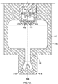
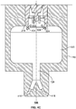
- FIG. 3A and FIG. 3B show a portion of the example igniter plug 200 and example antechamber 120.
- FIG. 3A shows arrows indicating flow into the antechamber 120 and igniter plug 200 prior to ignition of the air/fuel mixture.
- FIG. 3B shows arrows indicating flow out of the igniter plug 200 and the antechamber 120 after ignition of the air/fuel mixture has begun.
- the compressive action of the piston 104 forces a portion of the cool (relative to residual combustion gasses), fresh air/fuel mixture to flow from the combustion chamber 106 into the antechamber 120 through the openings 118 and central passage 126 ( FIG. 3A ).
- the central passage 126 operates as a nozzle, and in some instances a converging nozzle, to direct the flow into the antechamber.
- the central passage 126 has cross-sectional flow area equal to or less than the combined flow area of openings 118.
- the central passage 126 nozzles the incoming cool, fresh charge into a central high-velocity flow primarily directed to impinge on the end cap 204 and into the center opening 222 and peripheral openings 202 of the plug 200.
- the central flow has a higher velocity than flow elsewhere in the antechamber 120, and tends to displace residual combustion gasses away from the front of the igniter plug 200 and its openings 202, 222 to feed the cool, fresh air/fuel mixture into the forward zone 218 and into the flame initiation gap.
- a portion of the fresh air/fuel mixture entering the antechamber 120 does not enter the prechamber, but rather circulates within the antechamber 120 trapping the residuals displaced from in front of the igniter plug 200 into a recirculation loop away from the end of igniter plug 200 ( FIG. 3A ).
- the interior walls of the antechamber 120 are configured to direct the portion of the incoming flow into a toroidal vortex within the antechamber 120.
- the upper end of the antechamber 120 adjacent the entrance of the plug 200 has a wall that transitions in a smooth curve to the sidewalls of the antechamber 120. Flow from the central passage 126 impinging on or stagnating on the igniter plug 200 that is not received into the igniter body 128 is deflected laterally by the conical end of the igniter plug 200 and guided to circulate in a toroidal vortex by the upper end wall and the smooth curve to the sidewalls around the outer perimeter of the antechamber 120.
- the conical end of the igniter plug 200 and smooth curve to the sidewalls can be configured to reduce flow separation and other disturbances to the flow in creating this toroidal vortex.
- the upper end wall is orthogonal to the central axis of the plug 200 and antechamber 120 to guide the flow around to the outer perimeter of the sidewalls, but it could be another shape.
- the sidewalls transition in a smooth curve to the lower end of the antechamber 120.
- the lower end wall guides the circulating flow into the flow from the central passage 126 in a manner that encourages the circulating flow to turn and flow back upward.
- the walls guide the circulating flow to re-enter the flow from the passage 126 orthogonally (precisely and/or substantially) to the primary direction of flow or generally in the primary direction of the flow from the passage 126 (i.e., not counter to the primary direction of flow). Recombining the flow in this manner does not substantially counter the incoming flow, and thus substantially maintains the flow velocity from the central passage 126 to the igniter plug 200 that sweeps residuals in front of the plug 200 and feeds the igniter plug 200 with cool, fresh air/fuel mixture.
- the lower end wall is orthogonal to the central axis and directs the circulating flow orthogonally (precisely or substantially) into the flow from the central passage 126.
- the wall can have a non-zero angle (and introduce the flow at a non-zero angle) to the central axis and primary direction of flow from the central passage 126.
- the resulting circulation creates a toroidal vortex of flow in the antechamber 120 that provides a controlled degree of turbulence within the antechamber 120.
- the mixing of the flows creates turbulence.
- the toroidal vortex confines residual combustion gasses within the circulation in the antechamber 120, away from the igniter plug 200.
- the igniter plug 200 can have a depression (i.e., a bowl) located on the end. Prior to ignition, the depression collects the impinging central flow at exterior the end cap 204 by partially blocking lateral flow off the igniter plug 200 and creates a higher pressure in this region. Coupled with the high velocity of the central flow, this higher pressure tends to drive the central flow into the igniter forward zone 218 and creates a higher pressure within the prechamber than generally in the antechamber 120. (It should be noted that the pressure within prechamber is still less than that of the combustion chamber 106.) The air/fuel mixture impinging on the plug 200 flows into the igniter forward zone 218 through the center opening 222 and through the plurality of openings 202.
- a depression i.e., a bowl
- the center opening 222 directs the air/fuel mixture primarily to the interior of the velocity control tube 224 that, in turn, directs the flow into the flame kernel initiation gap between center ignition body 208 and tubular ignition body 210.
- the velocity control tube 224 collects the flow from the center opening 222 (by blocking lateral flow off the center ignition body 208) and causes the flow in the interior of the tube 224 to stagnate and create a higher pressure than the pressure around the exterior of the tube 224 and the pressure at the exit of the tubular ignition body 210.
- the velocity of the flow from the center opening 222 together with the pressure differential creates backward preferential velocity flow, guided by the velocity control tube 224 and tubular ignition body 210, through the flame initiation gap towards the back chamber 216 ( FIG. 3A ).
- the air/fuel mixture in the flame initiation gap is ignited in the flame kernel initiation gap (e.g. by a spark arcing between the central ignition body 208 and the tubular ignition body 210, by the heated surfaces of the central ignition body 208 and/or the tubular ignition body 210, and/or in another manner).
- the velocity of the air/fuel mixture in the gap causes the initial flame kernel to be transported into the back zone 216. Removal of the flame kernel from the flame initiation gap and into the back zone can, in certain instances, reduce the temperature of the flame initiation surfaces of the ignition bodies both because the kernel is moved away from the flame initiation surfaces quickly and because the flow from the central opening 222 is a constant source of cool (cooler than combustion products) air/fuel mixture.
- Reducing the temperature of the flame initiation surfaces reduces a primary factor in flame initiation plug loss of life: high temperature oxidation of the flame initiation surface in the presence of high temperature oxidizing environment. Removal of the flame kernel from the flame initiation gap also reduces the quenching effect of the ignition bodies 208, 210 on the growing flame kernel, thus, promoting a stronger kernel and healthier combustion event.
- the peripheral openings 202 are oriented to introduce a swirling motion to the incoming air/fuel mixture and direct flow primarily exterior of the tubular ignition body 210 and velocity control tube 224. Therefore, the swirling air/fuel mixture flows past the outside of the velocity control tube 224 and tubular ignition body 210 toward the back chamber 216 where it is ignited by the flame kernel.
- the velocity control tube 224 and tubular ignition bodies 210 act to shield and protect the flow in the flame initiation gap from flow disturbances due to the swirling motion of the surrounding outside flow until the kernel is established and exits from the rear of the tubular ignition body 210.
- the turbulence caused by the swirling motion of the air/fuel mixture distributes the growing flame kernel around the back chamber 216 predominantly consuming the air/fuel mixture in the back chamber 216 before consuming the air/fuel mixture in the igniter forward zone 218.
- the mean maximum pressure rise from combustion of the air/fuel mixture inside the igniter forward zone 218 is greater than 15 bar and, in certain instances, greater than 20 bar or 30 bar over the mean maximum pressure of the combustion chamber prior to ignition. Such pressures can be achieved without fuel feed or fuel enrichment into the igniter prechamber or antechamber 120.
- the increased pressure created in the prechamber by the combustion causes the combusting air/fuel mixture to jet out the openings 202, 222 as a flame and into the antechamber 120 ( FIG. 3B ).
- the enclosure protects the growing flame from turbulence (and relatively less quiescent flow patterns) in the antechamber 120 and in the combustion chamber 106.
- the antechamber 120 provides a large, volume in which the flow can be controlled so as to protect the flame source and where the flame can grow protected from turbulence in the combustion chamber 106.
- the vortex flow and turbulence inside the antechamber 120 promotes combustion, distributing the growing flame around the antechamber 120.
- the increased pressure generated by the growing flame in antechamber 120 forces the flame to jet out the openings 118 into the combustion chamber 106. Larger flame jets generated by the flame inside antechamber 120 cause faster and more complete combustion of the air/fuel mixture inside the combustion chamber 106 than would jets from the igniter openings 202, 222.
- the antechamber 120 can include active injection of fuel via a delivery tube into the antechamber 120 to enrich the mixture or into the prechamber spark plug volume as well.
- the turbulence generation in the antechamber is sufficient to generate fast enough turbulence enhanced combustion that fuel feed or fuel enrichment are not necessary to achieve rapid combustion and high pressure rise in the antechamber.
- ignition can be delayed by the flow of the flame kernel to the back chamber 216 and the flow of the flame back through the igniter forward zone 218 and antechamber 120 and into the combustion chamber 106. Because this increased ignition delay time results in a more complete burn, the process is more repeatable and has less variation, and therefore a lower COV.
- An additional benefit of the delay in ignition is that the flame initiation can be initiated sooner in the combustion cycle when the cylinder pressure is lower than would be the case without the ignition delay. Initiating the flame initiation when the cylinder pressure is lower prolongs the life of the flame initiation surfaces of the igniter plug 200. A lower cylinder pressure requires less voltage to initiate a flame initiation, and a lower power causes less erosion of the spark surfaces. In some implementations, the flame initiation can be initiated 10-12 degrees of crank angle earlier than a traditional flame initiation plug.
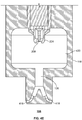
- FIGS. 4A-4G are cross-sectional views of several other example igniter plugs that can be used as igniter plug 124 and several other example antechambers. Except as described below, the additional example igniter plugs and antechambers of FIGS. 4A-4G are substantially similar to and operate similarly to the examples shown in FIGS. 1-3 .
- FIG. 4A has an end cap with a plurality of converging openings 402 that converge to the centerline of the igniter plug.
- the openings 402 operate as jet passages to nozzle combusting air/fuel mixture from the prechamber into divergent flame jets that reach deep into the antechamber 420 and ignite the charge in the antechamber 420.
- the openings 402 Prior to ignition, the openings 402 converge flow of cool, fresh air/fuel mixture into a jet of flow primarily oriented into the tubular body 224.
- the exterior openings of the openings 402 are within the bowl on the end of the igniter plug to facilitate entry of the fresh air/fuel mixture into the igniter forward zone 218. Peripheral openings may be included or omitted.
- FIG. 4B is an igniter plug that has no end cap, rather it has an open end.
- the shell 214 defines a cavity in the interior of the ignition plug, but the cavity is not enclosed.
- the open end presents no substantial flow restriction against cool, fresh air/fuel mixture flowing directly into the forward zone 218 and tubular body 224 prior to ignition.
- the incoming fresh charge increases the pressure in forward and back zones 218, 216 until a sufficiently high pressure rejects the incoming flow, redirecting a portion laterally to generate the toroidal vortex in the antechamber 420 described above.
- radial spokes holding the tubular body 224 and tubular ignition body 210 around the central ignition body 208 can be canted or angled to induce swirl within the back chamber 216.
- the swirl provides a specified degree of turbulence that facilitates rapid and complete combustion of the air/fuel mixture within the igniter plug that, in turn, ignites the charge in the antechamber 420.
- FIG. 4C is an igniter plug that has an end cap 404 that presents a female, converging cone to the flow incoming from the central passage 126 of the antechamber.
- the conic end cap 404 defines a single central opening, and may be provided with or without peripheral openings. Prior to ignition, the conic end cap 404 is a jet passage that converges and nozzles cool, fresh air/fuel mixture into the prechamber, with a substantial portion of the air/fuel mixture being primarily directed into the tubular body 224.
- the conic end cap 404 also directs a portion of the incoming fresh charge laterally to recirculate within the antechamber 420.
- the central opening is a jet passage that jets the flame present in the prechamber deeply into the antechamber 420 to ignite the air/fuel mixture in the antechamber 420.
- the end cap 406 can present a male, diverging cone to the flow incoming from the central passage 126 of the antechamber 420.
- FIG. 4E is an igniter plug has the ignition bodies 208, 210 extending into the antechamber 420.
- the tubular body 224 directs a portion of the incoming fresh charge from the central passage of the antechamber 420, outside of the tubular body 224 and laterally to recirculate and generate the toroidal vortex in the antechamber 420.
- the tubular ignition body 210 can extend back to the base 212 and have lateral holes to eject residuals (before ignition) and the flame kernel (after ignition) or can have one or more spaced apart legs extending back to the base.
- FIG. 4F is an igniter plug with a slotted disc 410 as end cap.
- An example slotted disc 410 is shown in FIG. 4H .
- the disc 410 has a central opening which directs incoming cool, fresh air/fuel mixture into the tubular body 224.
- the disc 410 also has a plurality of slots or holes surrounding the central opening.
- the slots can be canted or angled to generate a swirl within the incoming fresh charge.
- the slots and central opening are also jet passages that nozzle combusting air/fuel mixture from the prechamber into flame jets that reach deep into the antechamber 420 and ignite the charge in the antechamber 420.
- FIG. 4G is an igniter plug with an open end and a slotted disk 410 supporting the tubular body 224 and tubular ignition body 210.
- the example antechamber 420 is cylindrical rather than slightly tapered as in FIG. 3 , yet achieves the same toroidal vortex of circulation flow.
- the openings 418 are shaped to reduce loss of flow velocity of the flame from the antechamber to the combustion chamber and of the inflow of air/fuel mixture into the prechamber.
- the openings 418 can also have an exit angle that is complementary to the angle at the top of the piston. In certain instances, the exit angle can direct the flow parallel to the face of the piston and/or toward the face of the piston at a shallow angle.
- the openings 418 can meet with the central passage 126 at an angle that smoothly transitions incoming flow through the openings 418 into the central passage 126, for example, to reduce velocity losses into the prechamber.
- the openings 418 can be curved ( FIGS. 4A-4E ) or for manufacturing purposes formed of one or more straight sections ( FIGS. 4F , 4G ).
- FIG. 5 shows an exterior view of the carrier, showing that openings 418 can have one or more exterior profiles 518a, 518b of different size (i.e., flow area).
- the exterior profiles 518a have a smaller flow area than the profiles 518b.
- the smaller profiles 518a jet the flames a shorter distance into the combustion chamber than the larger-diameter openings 518b, in part because the jets from the smaller profiles 518a have less mass and momentum.
- the openings 518a, 518b can also have different angles to direct the flame jets into different regions of the combustion chamber 106. Flame jets with multiple distances or multiple angles can better fill the combustion chamber with flame jets to enable more complete combustion of the fuel/air mixture in combustion chamber 106.
- the antechamber and prechamber assembly also enables faster combustion. In some implementations, the combustion can occur in less than 20 degrees of crank angle in engines with a bore greater than 160 mm.
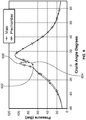
- FIG. 6 shows a graph of mean pressure in the main combustion chamber and in the igniter plug over crank angle for an example M18 sized igniter plug in an engine operating at 1500 rpm, with an effective compression ratio of 12 and indicated mean effective pressure (IMEP) or approximately 18 bar.
- the flow area into the pre-chamber enclosure of the igniter plug i.e., via the openings, such as openings 202, 222) is 60 mm 2 .
- Neither the pre-chamber enclosure nor the antechamber have an auxiliary fuel supply, and thus are only igniting the air/fuel mixture received from the combustion chamber.
- the pressure rise in the pre-chamber enclosure tracks and slightly trails the pressure rise in the combustion chamber prior to ignition.
- ignition has not yet begun in the combustion chamber.
- TDC top dead center
- the pressure in the pre-chamber enclosure rises over the pressure in the combustion chamber to a maximum mean pressure, at point 606, that is approximately 20 bar higher than the maximum mean pressure in the combustion chamber prior to ignition in the combustion chamber. This pressure rise is indicative of strong and healthy ignition and combustion within the pre-chamber enclosure.
- ignition in the combustion chamber begins as flames are jetted from the antechamber into the combustion chamber, and the pressure rises to reach the maximum post ignition pressure in the combustion chamber.
- the flow area into the pre-chamber enclosure (noted above as being 60 mm 2 ) affects the pressure rise in the chamber, as well as the rate air/fuel mixture is exchanged in and out of the igniter plug.
- One measure of the strength of the ignition in the pre-chamber is the product of this flow area times the pressure rise in the pre-chamber.
- the igniter plug without an auxiliary supply of fuel, can achieve a maximum mean pressure in the pre-chamber enclosure after ignition in the pre-chamber enclosure and before ignition in the combustion chamber time the flow area into the pre-chamber enclosure to be 1200 bar-sqmm or greater.
Landscapes
- Engineering & Computer Science (AREA)
- Chemical & Material Sciences (AREA)
- Combustion & Propulsion (AREA)
- Mechanical Engineering (AREA)
- General Engineering & Computer Science (AREA)
- Combustion Methods Of Internal-Combustion Engines (AREA)
- Ignition Installations For Internal Combustion Engines (AREA)
- Spark Plugs (AREA)
Claims (14)
- System zum Zünden eines Gemischs in einer Brennkraftmaschine (100), wobei das System Folgendes umfasst:einen Steckerkörper, der eine Hülle (214) umfasst;einen ersten Zündkörper (208), der durch den Steckerkörper in der Hülle (214) getragen wird;einen zweiten Zündkörper (210), der durch den Steckerkörper in der Hülle (214) und neben dem ersten Zündkörper (208) getragen wird, um einen Flammenkerninitiierungsspalt zwischen dem zweiten Zündkörper (210) und dem ersten Zündkörper (208) zu definieren;eine Einhausung, die einen Strahldurchgang (118, 126) umfasst, dadurch gekennzeichnet, dass sie eine Kammer (120) um ein Ende der Hülle (214) definiert, die ein größeres Volumen als ein Innenraum der Hülle (214), der ein Fluid enthält, besitzt, wobei die Kammer (120) Innenwände, die eine obere Stirnwand, Seitenwände und eine untere Stirnwand enthalten, besitzt, die ausgelegt sind, einen durch den Strahldurchgang (118) eingehenden Strom derart zu leiten, dass er in der Kammer (120) zirkuliert und mit dem eingehenden Strom angrenzend an den Strahldurchgang (118) und senkrecht zu oder im Wesentlichen in der Richtung des eingehenden Stroms neu kombiniert wird.
- System nach Anspruch 1, wobei die Einhausung ein äußere Einhausung umfasst und die Kammer (120) eine Außenkammer umfasst und
das System ferner eine innere Einhausung in der Außenkammer (120) umfasst, die eine Innenkammer (216, 218) definiert, die den ersten und den zweiten Zündkörper (208, 210) einschließt, wobei die innere Einhausung einen Strahldurchgang (202, 222; 402) umfasst, der ausgelegt ist, einen Strom, der durch den Strahldurchgang (202, 222; 402) der inneren Einhausung eingeht, im Wesentlichen zum ersten und zum zweiten Zündkörper (208, 210) zu leiten. - System nach Anspruch 2, wobei der Strahldurchgang (118) der äußeren Einhausung einen zentralen Durchgang (126) umfasst, der orientiert ist, um einen eingehenden Strom derart zu leiten, dass er auf die innere Einhausung prallt; und
der Strahldurchgang (202, 222; 402) der inneren Einhausung einen zentralen Strahldurchgang (222) umfasst, der orientiert ist, einen Strom, der auf die innere Einhausung prallt, aufzunehmen und den aufgenommenen Strom im Wesentlichen zum Flammenkerninitiierungsspalt zu leiten. - System nach einem der Ansprüche 1 bis 3, wobei der zweite Zündkörper (210) den ersten Zündkörper (208) umgibt und einen rohrförmigen Abschnitt (224) umfasst, der axial nach vorne über den ersten Zündkörper (208) verläuft.
- System nach einem der Ansprüche 1 bis 4, wobei die innere Einhausung Folgendes umfasst:
einen peripheren Strahldurchgang (202), der ausgelegt ist, einen Strom aufzunehmen, der auf die innere Einhausung prallt, und den aufgenommenen Strom zu einer äußeren Umgebung des zweiten Zündkörpers (210) zu leiten und in der inneren Einhausung einen Drall zu erzeugen. - System nach Anspruch 5, wobei der zweite Zündkörper (210) ausgelegt ist, zu bewirken, dass der Strom im Zündspalt nach hinten strömt, und einen Strom im Zündspalt vor Störungen vom Strom vom peripheren Strahldurchgang (202) zu schützen.
- System nach einem der Ansprüche 3 bis 6, wobei die innere Einhausung konisch ist und ausgelegt ist, einen Strom vom zentralen Durchgang (126) seitlich zu einer Seitenwand der Außenkammer (120) abzulenken.
- System nach Anspruch 7, wobei die Außenkammer (120) derart geformt ist, dass sie einen Strom vom zentralen Durchgang (120) derart leitet, dass er einen im Wesentlichen ringförmigen Stromwirbel in der Außenkammer (120) erzeugt und Verwirbelungen in der Außenkammer (120) erzeugt.
- System nach einem der vorhergehenden Ansprüche, das ein röhrenförmiges Empfängergehäuse (116), das die Einhausung umfasst, umfasst, wobei das Empfängergehäuse (116) ausgelegt ist, den Steckerkörper aufzunehmen und an ihn gekoppelt zu werden, und ausgelegt ist, an die Brennkraftmaschine (100) gekoppelt zu werden.
- System nach einem der vorhergehenden Ansprüche, wobei der zweite Zündkörper (210) eine Rohr ist, das ohne Unterbrechungen kontinuierlich ist.
- Verfahren zum Zünden eines Luft/Kraftstoff-Gemischs in einer Brennkraftmaschine (100), wobei das Verfahren Folgendes umfasst:Aufnehmen des Luft/Kraftstoff-Gemischs als ein eingehendes Luft/Kraftstoff-Gemisch von einer Brennkammer der Brennkraftmaschine in eine Einhausung, die an die Brennkammer angrenzt;Leiten des empfangenen Luft/Kraftstoff-Gemischs in die Einhausung zu einem ersten und einem zweiten Zündkörper (208, 210) und derart, dass es in der Einhausung zirkuliert und mit dem eingehenden Luft/Kraftstoff-Gemischstrom senkrecht zu oder im Wesentlichen in der Richtung des eingehenden Luft/Kraftstoff-Gemischstroms neu kombiniert wird, wobei die Einhausung eine äußere Einhausung ist und das Leiten des empfangenen Luft/Kraftstoff-Gemischs in die äußere Einhausung zum ersten und zum zweiten Zündkörper (208, 210) das Leiten des empfangenen Luft/Kraftstoff-Gemischs in die äußere Einhausung derart umfasst, dass er auf einen innere Einhausung in der äußeren Einhausung prallt, wobei der Strom durch Innenwände, die eine obere Stirnwand, Seitenwände und eine untere Stirnwand der äußeren Einhausung enthalten, geleitet wird;Empfangen des Luft/Kraftstoff-Gemischs, das auf die innere Einhausung prallt, in der inneren Einhausung und Leiten des empfangenen Luft/Kraftstoff-Gemischs in die innere Einhausung in den Flammenkerninitiierungsspalt undZünden des Luft/Kraftstoff-Gemischs in einem Flammenkerninitiierungsspalt zwischen dem ersten und dem zweiten Zündkörper (208, 210).
- Verfahren nach Anspruch 11, wobei das Leiten des empfangenen Luft/Kraftstoff-Gemischs in die äußere Einhausung derart, dass es auf eine innere Einhausung prallt, ein Verdrängen von Verbrennungsresten um einen Durchgang durch das Innengehäuse umfasst.
- Verfahren nach Anspruch 11 oder 12, das ein Leiten des Luft/Kraftstoff-Gemischs, das geleitet wird, auf die innere Einhausung zu prallen, derart umfasst, dass es einen ringförmigen Wirbel in der äußeren Einhausung erzeugt.
- Verfahren nach einem der Ansprüche 11 bis 13, wobei das Leiten des empfangenen Luft/Kraftstoff-Gemischs in die innere Einhausung in einen Flammenkerninitiierungsspalt ein Leiten des Luft/Kraftstoff-Gemischs mit einem zentralen Durchgang (222) der inneren Einhausung im Wesentlichen in den Flammenkerninitiierungsspalt umfasst;
ein Leiten des empfangenen Luft/Kraftstoff-Gemischs in die innere Einhausung mit einem Umfangsdurchgang (202) der inneren Einhausung umfasst, derart, dass ein Drall um eine äußere Umgebung des zweiten Zündkörpers (210) erzeugt wird; und
ein Schützen des Luft/Kraftstoff-Gemischs im Flammenkerninitiierungsspalt vor Stromstörungen vom verwirbelten Luft/Kraftstoff-Gemisch im zweiten Zündkörper (210) umfasst.
Applications Claiming Priority (2)
| Application Number | Priority Date | Filing Date | Title |
|---|---|---|---|
| US13/913,840 US8839762B1 (en) | 2013-06-10 | 2013-06-10 | Multi-chamber igniter |
| PCT/US2014/041758 WO2014201030A1 (en) | 2013-06-10 | 2014-06-10 | Mutli-chamber igniter |
Publications (2)
| Publication Number | Publication Date |
|---|---|
| EP2836690A1 EP2836690A1 (de) | 2015-02-18 |
| EP2836690B1 true EP2836690B1 (de) | 2019-08-07 |
Family
ID=51059657
Family Applications (1)
| Application Number | Title | Priority Date | Filing Date |
|---|---|---|---|
| EP14734707.4A Active EP2836690B1 (de) | 2013-06-10 | 2014-06-10 | Zündkerze mit neben- und hauptbrennraum |
Country Status (5)
| Country | Link |
|---|---|
| US (1) | US8839762B1 (de) |
| EP (1) | EP2836690B1 (de) |
| JP (1) | JP6060260B2 (de) |
| CN (1) | CN105431620B (de) |
| WO (1) | WO2014201030A1 (de) |
Families Citing this family (59)
| Publication number | Priority date | Publication date | Assignee | Title |
|---|---|---|---|---|
| US9476347B2 (en) * | 2010-11-23 | 2016-10-25 | Woodward, Inc. | Controlled spark ignited flame kernel flow in fuel-fed prechambers |
| US9172217B2 (en) | 2010-11-23 | 2015-10-27 | Woodward, Inc. | Pre-chamber spark plug with tubular electrode and method of manufacturing same |
| US8584648B2 (en) * | 2010-11-23 | 2013-11-19 | Woodward, Inc. | Controlled spark ignited flame kernel flow |
| JP6175143B2 (ja) * | 2012-09-06 | 2017-08-02 | プロメテウス アプライド テクノロジーズ,エルエルシー | 大口径ガスエンジン用2段式予燃焼室 |
| JP6076662B2 (ja) * | 2012-09-20 | 2017-02-08 | 三菱重工業株式会社 | 副室式ガスエンジン |
| US9856848B2 (en) | 2013-01-08 | 2018-01-02 | Woodward, Inc. | Quiescent chamber hot gas igniter |
| US10024220B2 (en) * | 2013-03-12 | 2018-07-17 | Prometheus Applied Technologies, Llc | Active scavenge prechamber |
| ES2651167T3 (es) * | 2013-03-12 | 2018-01-24 | Prometheus Applied Technologies, Llc | Precámara de barrido activo |
| US9765682B2 (en) | 2013-06-10 | 2017-09-19 | Woodward, Inc. | Multi-chamber igniter |
| EP3180504B1 (de) * | 2014-08-13 | 2021-03-17 | Woodward, Inc. | Mehrkammerzünder |
| US10584639B2 (en) | 2014-08-18 | 2020-03-10 | Woodward, Inc. | Torch igniter |
| WO2016057556A1 (en) * | 2014-10-06 | 2016-04-14 | Advanced Green Innovations, LLC | Structures to insulate ignition system high-voltage within a direct injection gaseous diffusion burn fuel prechamber |
| US9593622B2 (en) | 2015-02-09 | 2017-03-14 | Caterpillar Inc. | Combustion system, nozzle for prechamber assembly, and method of making same |
| AT516835B1 (de) * | 2015-03-13 | 2016-09-15 | Er-System Mechatronik Gmbh | Zündkerze |
| US9653886B2 (en) * | 2015-03-20 | 2017-05-16 | Woodward, Inc. | Cap shielded ignition system |
| US9840963B2 (en) | 2015-03-20 | 2017-12-12 | Woodward, Inc. | Parallel prechamber ignition system |
| US9739192B2 (en) | 2015-05-04 | 2017-08-22 | Caterpillar Inc. | Fuel combustion system, nozzle for prechamber assembly with curved orifices, and method of making same |
| US9617908B2 (en) * | 2015-05-11 | 2017-04-11 | Caterpillar Inc. | Fuel combustion system, nozzle for prechamber assembly having coolant passage, and method of making same |
| AT14789U1 (de) * | 2015-05-12 | 2016-06-15 | Avl List Gmbh | Vorkammerzündeinrichtung für eine Brennkraftmaschine |
| US10161306B2 (en) * | 2015-06-11 | 2018-12-25 | Rem Technology Inc. | Natural gas engines to reduce NOx emissions |
| US9890690B2 (en) | 2015-10-06 | 2018-02-13 | Woodward, Inc. | Passive prechamber direct injection combustion |
| DE102015117113B4 (de) | 2015-10-07 | 2017-06-01 | Federal-Mogul Ignition Gmbh | Vorkammerzündkerze für eine mit Gas betriebene Brennkraftmaschine |
| CN114439600A (zh) * | 2015-10-08 | 2022-05-06 | 康明斯公司 | 预燃室组件 |
| US10066580B2 (en) * | 2015-10-15 | 2018-09-04 | The Regents Of The University Of Michigan | Lean burn internal combustion engine |
| US9890689B2 (en) | 2015-10-29 | 2018-02-13 | Woodward, Inc. | Gaseous fuel combustion |
| EP3173596B1 (de) * | 2015-11-25 | 2020-04-01 | Caterpillar Energy Solutions GmbH | Vorverbrennungskammeranordnung für verbrennungsmotoren |
| EP3181855B1 (de) | 2015-12-14 | 2018-08-29 | Caterpillar Energy Solutions GmbH | Vorkammer eines verbrennungsmotors |
| US10208651B2 (en) | 2016-02-06 | 2019-02-19 | Prometheus Applied Technologies, Llc | Lean-burn pre-combustion chamber |
| JP6498223B2 (ja) * | 2016-02-06 | 2019-04-10 | プロメテウス アプライド テクノロジーズ,エルエルシー | 希薄燃焼予燃焼室 |
| US10060334B2 (en) * | 2016-06-01 | 2018-08-28 | Ford Global Technologies, Llc | Controlled air entrainment passage for diesel engines |
| GB2552669B (en) * | 2016-08-02 | 2019-12-11 | Caterpillar Energy Solutions Gmbh | Engine pre-chamber |
| CN106224153A (zh) * | 2016-08-30 | 2016-12-14 | 合肥恒信汽车发动机部件制造有限公司 | 一种发动机点火机构及其点火方法 |
| JP6930829B2 (ja) | 2016-12-12 | 2021-09-01 | 三菱重工エンジン&ターボチャージャ株式会社 | 副室式ガスエンジン |
| DK179281B1 (en) * | 2016-12-13 | 2018-04-03 | Man Diesel & Turbo Filial Af Man Diesel & Turbo Se Tyskland | Nozzle for fuel valve for injecting fuel into the cylinders of a large turbocharged two-stroke compression-ignited internal combustion engine |
| DE102017107728A1 (de) | 2017-04-10 | 2018-10-11 | Federal-Mogul Ignition Gmbh | Vorkammerzündkerze und Verfahren zu deren Herstellung |
| US10837369B2 (en) * | 2017-08-23 | 2020-11-17 | General Electric Company | Igniter assembly for a gas turbine combustor |
| US10174667B1 (en) * | 2017-11-17 | 2019-01-08 | Caterpillar Inc. | Prechamber ignition device for internal combustion engines and method |
| DE102018007093A1 (de) * | 2018-09-07 | 2020-03-12 | Daimler Ag | Vorkammerzündkerze für einen Brennraum einer Verbrennungskraftmaschine, insbesondere eines Kraftfahrzeugs |
| JP7095570B2 (ja) * | 2018-11-26 | 2022-07-05 | トヨタ自動車株式会社 | 副室付内燃機関 |
| GB201820560D0 (en) * | 2018-12-17 | 2019-01-30 | Aston Martin Lagonda Ltd | Assemblies for engines |
| US11421601B2 (en) | 2019-03-28 | 2022-08-23 | Woodward, Inc. | Second stage combustion for igniter |
| US11002178B1 (en) * | 2020-01-21 | 2021-05-11 | Ford Global Technologies, Llc | Methods and systems for a pre-chamber |
| WO2021153275A1 (ja) * | 2020-01-29 | 2021-08-05 | 株式会社デンソー | 点火システム |
| US11326509B2 (en) * | 2020-02-14 | 2022-05-10 | Vianney Rabhi | Valve ignition prechamber with a reversed directon of combustion |
| DE102020110395B4 (de) * | 2020-04-16 | 2026-04-16 | Bayerische Motoren Werke Aktiengesellschaft | Fremd gezündete Hubkolben-Brennkraftmaschine mit einem Vorkammerzündsystem |
| US10938187B1 (en) | 2020-05-08 | 2021-03-02 | Caterpillar Inc. | Prechamber sparkplug having electrodes located for inhibiting flame kernel quenching |
| US12305578B2 (en) | 2020-06-23 | 2025-05-20 | Woodward, Inc. | Ignition system for power generation engine |
| JP2022063921A (ja) * | 2020-10-13 | 2022-04-25 | 日立Astemo株式会社 | 内燃機関およびプレチャンバー |
| DE102021000855B3 (de) * | 2021-02-18 | 2022-08-18 | Mercedes-Benz Group AG | Vorkammerzündkerze für eine Verbrennungskraftmaschine, Verbrennungskraftmaschine sowie Verfahren zum Herstellen einer solchen Vorkammerzündkerze |
| EP4314513B1 (de) * | 2021-03-30 | 2025-05-07 | Wärtsilä Finland Oy | Vorkammer, zylinderkopf und kolbenmotor |
| CN114542315B (zh) * | 2022-01-18 | 2023-02-21 | 北京理工大学 | 一种湍射流自燃着火发动机 |
| WO2024015269A1 (en) | 2022-07-12 | 2024-01-18 | Prometheus Applied Technologies, Llc | Predictive model-based spark control |
| EP4424981B1 (de) | 2023-03-03 | 2025-05-07 | Volvo Truck Corporation | Verfahren zum betreiben einer verbrennungskraftmaschinenanlage unter verwendung von wasserstoff-kraftstoff |
| DE102023105825B3 (de) | 2023-03-09 | 2024-08-01 | Bayerische Motoren Werke Aktiengesellschaft | Vorkammerzündeinrichtung für eine Verbrennungskraftmaschine, insbesondere eines Kraftfahrzeugs, sowie Verbrennungskraftmaschine, insbesondere für ein Kraftfahrzeug |
| DK181704B1 (en) * | 2023-03-24 | 2024-10-21 | Man Energy Solutions Filial Af Man Energy Solutions Se Tyskland | A fuel valve for injecting fuel into the cylinders of a large turbocharged two-stroke uniflow scavenged internal combustion engine and an engine with such fuel valve |
| US12228068B1 (en) | 2024-06-03 | 2025-02-18 | Prometheus Applied Technologies, Llc | Predictive model-based spark control |
| CA3253577A1 (en) * | 2023-08-31 | 2025-06-03 | Brp-Rotax Gmbh & Co. Kg | Internal combustion engine with combustion pre-chamber |
| CN117889011B (zh) * | 2023-12-28 | 2026-03-27 | 长城汽车股份有限公司 | 缸盖、发动机和车辆 |
| EP4653677A1 (de) * | 2024-05-21 | 2025-11-26 | Pankl Racing Systems AG | Kolbenmotor und verfahren zum betreiben eines kolbenmotors |
Citations (1)
| Publication number | Priority date | Publication date | Assignee | Title |
|---|---|---|---|---|
| DE3120007A1 (de) * | 1981-05-20 | 1982-12-09 | Robert Bosch Gmbh, 7000 Stuttgart | Nebenbrennraum fuer eine brennkraftmaschine mit wenigstens einem hubkolben und einem hauptbrennraum |
Family Cites Families (157)
| Publication number | Priority date | Publication date | Assignee | Title |
|---|---|---|---|---|
| US1320115A (en) | 1919-10-28 | Flame-projector spark-plug | ||
| US1360294A (en) | 1920-11-30 | Spark-plttg | ||
| US2899585A (en) | 1959-08-11 | dollenberg | ||
| US1325439A (en) | 1919-12-16 | Spark-plug | ||
| US1009867A (en) | 1911-04-03 | 1911-11-28 | George Orvill Terry | Spark-plug. |
| US1253570A (en) | 1916-08-30 | 1918-01-15 | W W George | Spark-plug. |
| US1242375A (en) | 1917-01-15 | 1917-10-09 | Frank Robinson | Spark-plug. |
| US1361580A (en) | 1917-11-02 | 1920-12-07 | Gustave L Herz | Spark-plug |
| US1361347A (en) | 1919-12-08 | 1920-12-07 | George O Nighswander | Spark-plug |
| US1538750A (en) | 1922-08-25 | 1925-05-19 | Scognamillo Salvatore | Spark plug |
| US1596240A (en) | 1924-09-08 | 1926-08-17 | Myron J Dikeman | Ignition flash plug |
| US1963801A (en) | 1933-03-14 | 1934-06-19 | O'marra Martin | Spark plug |
| FR764079A (fr) | 1933-11-20 | 1934-05-14 | Bougie d'allumage | |
| US2047575A (en) | 1935-07-02 | 1936-07-14 | Richard J Burtnett | Spark plug |
| US2153598A (en) | 1936-04-02 | 1939-04-11 | George K Steward | Internal combustion engine |
| US2127513A (en) | 1937-05-25 | 1938-08-23 | H B Motor Corp | Spark plug |
| US2208030A (en) | 1939-11-06 | 1940-07-16 | Holmes Induction Deviees Inc | Spark plug |
| US2314128A (en) | 1940-04-01 | 1943-03-16 | Globe Union Inc | Spark plug and method of making the same |
| US2299924A (en) | 1941-04-11 | 1942-10-27 | Frederick A Ost | Spark plug |
| GB588074A (en) | 1944-01-29 | 1947-05-13 | Mallory Metallurg Prod Ltd | Improvements in and connected with sparking plugs |
| US2416107A (en) | 1945-03-28 | 1947-02-18 | Bendix Aviat Corp | Spark plug |
| US2487535A (en) | 1945-06-13 | 1949-11-08 | John J Fernandez | Spark plug |
| US2497862A (en) | 1948-06-18 | 1950-02-21 | Herbnick Mfg And Engineering C | Spark plug for controlling heat ranges |
| FR985788A (fr) | 1949-05-09 | 1951-07-23 | Bougie d'allumage pour moteurs à combustion interne | |
| US2586864A (en) | 1950-08-22 | 1952-02-26 | John J Rose | Spark plug electrode |
| US2843780A (en) | 1952-01-31 | 1958-07-15 | Jet Ignition Company Inc | Spark plugs |
| US2776394A (en) | 1953-02-26 | 1957-01-01 | Bendix Aviat Corp | Screened spark plug |
| US2895069A (en) | 1954-10-08 | 1959-07-14 | Jet Ignition Co Inc | Spark plugs |
| US2957099A (en) | 1959-09-18 | 1960-10-18 | Hastings Mfg Co | Spark plugs |
| US3300672A (en) | 1963-05-27 | 1967-01-24 | Neutronic Dev Corp | Spark plug with anti-fouling means and fixed spark gap |
| FR2071129A5 (de) | 1969-12-18 | 1971-09-17 | Thery Georges | |
| DE2112815A1 (de) | 1971-03-17 | 1972-10-05 | Bosch Gmbh Robert | Flammkerze als Anlasshilfe fuer Diesel- und Vielstoffmotoren |
| IT1022391B (it) | 1973-10-01 | 1978-03-20 | Franks Harry E | Candela di accensione per motori |
| US3958144A (en) | 1973-10-01 | 1976-05-18 | Franks Harry E | Spark plug |
| JPS5077738U (de) | 1973-11-19 | 1975-07-05 | ||
| JPS5252013A (en) * | 1975-10-22 | 1977-04-26 | Niigata Eng Co Ltd | Diesel engine combustion unti |
| DE2549933A1 (de) | 1975-11-07 | 1977-05-12 | Porsche Ag | Vorkammer im zylinderkopf einer fremdgezuendeten brennkraftmaschine |
| SU968493A1 (ru) | 1976-04-22 | 1982-10-23 | Государственный Научно-Исследовательский Энергетический Институт Им.Г.М.Кржижановского | Форкамера |
| JPS5349643A (en) | 1976-10-19 | 1978-05-06 | Ngk Spark Plug Co Ltd | Rear electrode type spark plug with long discharge gap |
| US4124000A (en) | 1976-11-03 | 1978-11-07 | General Motors Corporation | Mixed cycle stratified charge engine with ignition antechamber |
| JPS5718283Y2 (de) | 1977-07-20 | 1982-04-16 | ||
| US4218993A (en) | 1979-03-14 | 1980-08-26 | Blackburn Donald E | Method and apparatus for accomplishing flame ignition for an internal combustion engine |
| CH624509A5 (de) | 1980-05-30 | 1981-07-31 | Espada Anstalt | |
| DE3025926A1 (de) | 1980-07-09 | 1982-02-04 | Robert Bosch Gmbh, 7000 Stuttgart | Fremdgezuendete brennkraftmaschine mit wenigstens einem hauptbrennraum und einer diesem zugeordneten zuendkammer |
| DE3148296A1 (de) | 1981-01-17 | 1982-09-02 | Robert Bosch Gmbh, 7000 Stuttgart | Fremdgezuendete brennkraftmaschine mit wenigstens einem hauptbrennraum und einer diesem zugeordneten zuendkammer |
| JPS58162719U (ja) | 1982-04-21 | 1983-10-29 | 共同電気株式会社 | 建物におけるバスダクト貫通部の閉塞装置 |
| DE3230793A1 (de) | 1982-08-19 | 1984-02-23 | Robert Bosch Gmbh, 7000 Stuttgart | Zuendvorrichtung fuer brennkraftmaschinen |
| DE3241697A1 (de) | 1982-11-11 | 1984-05-17 | Robert Bosch Gmbh, 7000 Stuttgart | Zuendvorrichtung mit einer zuendkammer und zuendelektroden |
| DE3544176C1 (de) | 1985-12-13 | 1987-05-21 | Beru Werk Ruprecht Gmbh Co A | Zuendkerze mit kombinierten Gleit- und Luftfunkenstrecken |
| JPH0311575Y2 (de) | 1986-04-11 | 1991-03-20 | ||
| SU1370269A1 (ru) | 1986-05-16 | 1988-01-30 | Тюменский индустриальный институт им.Ленинского комсомола | Газовый двигатель внутреннего сгорани |
| DE3619938A1 (de) | 1986-06-13 | 1987-12-17 | Bayerische Motoren Werke Ag | Zuendkerze fuer brennkraftmaschinen |
| DE3816968A1 (de) | 1988-05-18 | 1989-11-30 | Beru Werk Ruprecht Gmbh Co A | Zuendkerze |
| JPH02117086A (ja) | 1988-10-26 | 1990-05-01 | Ryohei Kashiwabara | 点火栓並びに点火栓ににる燃焼方法 |
| US5051651A (en) | 1988-11-24 | 1991-09-24 | Tadaharu Fujiwara | Ignition plug with a hollow cylindrical ground electrode and an ignition process by the use thereof |
| JPH02148588A (ja) | 1988-11-28 | 1990-06-07 | Masami Fujii | 長接地電極材を地中深く打設設置する接地工法 |
| US4930473A (en) | 1988-12-09 | 1990-06-05 | Texas Ignitors Company, Inc. | Swirl chamber and spark plug assembly |
| DE8902032U1 (de) | 1989-02-21 | 1989-05-18 | Jenbacher Werke AG, Jenbach, Tirol | Zündkerze |
| DE3913665A1 (de) | 1989-04-26 | 1990-10-31 | Ruhrgas Ag | Vorkammer-zuendeinrichtung |
| US4987868A (en) | 1989-05-08 | 1991-01-29 | Caterpillar Inc. | Spark plug having an encapsulated center firing electrode gap |
| EP0451264B1 (de) | 1989-10-13 | 1995-12-27 | Ultra Performance International | Zündkerze mit einer massenelektrode in form eines offenen ringes |
| US5430346A (en) | 1989-10-13 | 1995-07-04 | Ultra Performance International, Inc. | Spark plug with a ground electrode concentrically disposed to a central electrode and having precious metal on firing surfaces |
| US5014656A (en) | 1990-04-25 | 1991-05-14 | General Motors Corporation | Internal combustion engine having a permanent ground electrode and replaceable center electrode element |
| DE59106432D1 (de) | 1990-07-02 | 1995-10-12 | Jenbacher Energiesysteme Ag | Zündkerze. |
| US5105780A (en) | 1990-08-08 | 1992-04-21 | Caterpillar Inc. | Ignition assisting device for internal combustion engines |
| US5647444A (en) | 1992-09-18 | 1997-07-15 | Williams; John R. | Rotating blowout preventor |
| US5662181A (en) | 1992-09-30 | 1997-09-02 | Williams; John R. | Rotating blowout preventer |
| US5408961A (en) | 1993-08-09 | 1995-04-25 | Innovative Automative Technologies Int. Ltd. | Ignition plug |
| US5421300A (en) | 1994-02-28 | 1995-06-06 | General Motors Corporation | Torch jet spark plug |
| EP0675272B1 (de) | 1994-03-29 | 1997-08-06 | Dieter Dr. Kuhnert | Vorkammerzündeinrichtung |
| RU2116474C1 (ru) | 1994-06-07 | 1998-07-27 | Вячеслав Григорьевич Моргунов | Выносная форкамера для двигателя внутреннего сгорания |
| DE4422939C2 (de) | 1994-06-30 | 2000-05-31 | Bosch Gmbh Robert | Zündkerze für eine Brennkraftmaschine |
| US5619959A (en) | 1994-07-19 | 1997-04-15 | Cummins Engine Company, Inc. | Spark plug including magnetic field producing means for generating a variable length arc |
| US5555862A (en) | 1994-07-19 | 1996-09-17 | Cummins Engine Company, Inc. | Spark plug including magnetic field producing means for generating a variable length arc |
| JPH08260970A (ja) * | 1995-03-20 | 1996-10-08 | Tokyo Gas Co Ltd | 副室式ガス機関の副室形状 |
| JPH0955282A (ja) | 1995-06-08 | 1997-02-25 | Ngk Spark Plug Co Ltd | スパークプラグ |
| US5623179A (en) | 1995-12-04 | 1997-04-22 | Buhl; Richard | Multi fire spark plug |
| US5892319A (en) | 1996-01-04 | 1999-04-06 | Rossi; Paul | Top and side firing spark plug |
| US5799637A (en) | 1996-05-01 | 1998-09-01 | Cifuni; Charles G. | Rocket effect sparking plug |
| DE19624965A1 (de) | 1996-06-22 | 1998-01-02 | Motoren Werke Mannheim Ag | Zündsystem für einen Gasmotor |
| BR9712894A (pt) | 1996-11-07 | 2000-03-21 | Pier Andrea Rigazzi | l e para sua ignição em uma pré-câmara que é aberta sobre os cilindros |
| DE19705372C2 (de) | 1997-02-12 | 2002-06-27 | Beru Werk Ruprecht Gmbh Co A | Zündkerze für eine Brennkraftmaschine |
| US6060822A (en) | 1997-07-21 | 2000-05-09 | Century Development International Ltd. | Spark plug |
| US6013973A (en) | 1997-10-24 | 2000-01-11 | Sato; Jun | Spark plug having a sub-combustion chamber for use in fuel ignition systems |
| US6198209B1 (en) | 1997-12-22 | 2001-03-06 | Caterpillar Inc. | Shielded spark plug electrode |
| US6130498A (en) | 1997-12-26 | 2000-10-10 | Denso Corporation | Spark plug with specific measured parameters |
| US6913092B2 (en) | 1998-03-02 | 2005-07-05 | Weatherford/Lamb, Inc. | Method and system for return of drilling fluid from a sealed marine riser to a floating drilling rig while drilling |
| US6495948B1 (en) | 1998-03-02 | 2002-12-17 | Pyrotek Enterprises, Inc. | Spark plug |
| US5947076A (en) * | 1998-04-17 | 1999-09-07 | Caterpillar Inc. | Fuel combustion assembly for an internal combustion engine having an encapsulated spark plug for igniting lean gaseous fuel within a precombustion chamber |
| US6129152A (en) | 1998-04-29 | 2000-10-10 | Alpine Oil Services Inc. | Rotating bop and method |
| US6213085B1 (en) | 1999-02-02 | 2001-04-10 | Delphi Technologies, Inc. | Directed jet spark plug |
| US6670740B2 (en) | 1999-05-12 | 2003-12-30 | William W. Landon, Jr. | High electrical stiction spark plug |
| US6326719B1 (en) | 1999-06-16 | 2001-12-04 | Alliedsignal Inc. | Spark plug shell having a bimetallic ground electrode spark plug incorporating the shell, and method of making same |
| JP2001160474A (ja) | 1999-09-24 | 2001-06-12 | Ngk Spark Plug Co Ltd | スパークプラグ |
| JP4262388B2 (ja) | 2000-05-19 | 2009-05-13 | オリンパス株式会社 | 電子カメラ |
| US6460506B1 (en) | 2000-09-14 | 2002-10-08 | Caterpillar Inc. | Spark plug having an encapsulated electrode gap |
| JP2002184551A (ja) | 2000-10-03 | 2002-06-28 | Nippon Soken Inc | スパークプラグ及びそれを用いた点火装置 |
| US6554016B2 (en) | 2000-12-12 | 2003-04-29 | Northland Energy Corporation | Rotating blowout preventer with independent cooling circuits and thrust bearing |
| US6611083B2 (en) | 2000-12-15 | 2003-08-26 | Savage Enterprises, Inc. | Torch jet spark plug electrode |
| AT410151B (de) | 2001-06-05 | 2003-02-25 | Jenbacher Ag | Zündkerze einer brennkraftmaschine |
| DE10144976A1 (de) | 2001-09-12 | 2003-04-03 | Beru Ag | Zündkerze mit Mittelelektrode und Vorkammer |
| DE10232035B4 (de) | 2002-07-16 | 2021-10-14 | Hilti Aktiengesellschaft | Brennkraftbetriebenes Setzgerät |
| JP4133281B2 (ja) | 2002-12-10 | 2008-08-13 | シャープ株式会社 | 異物除去機構,印刷装置および異物除去方法 |
| FR2846042B1 (fr) | 2002-10-18 | 2005-02-04 | Peugeot Citroen Automobiles Sa | Dispositif d'allumage a prechambre realisee dans un materiau a conductivite thermique elevee, pour un moteur a combustion interne, et allumeur a prechambre |
| FR2846046B1 (fr) | 2002-10-18 | 2006-06-16 | Peugeot Citroen Automobiles Sa | Dispositif d'allumage a prechambre pour un moteur a combustion interne, allumeur a prechambre et procede d'allumage |
| US7836946B2 (en) | 2002-10-31 | 2010-11-23 | Weatherford/Lamb, Inc. | Rotating control head radial seal protection and leak detection systems |
| US20040100179A1 (en) | 2002-11-25 | 2004-05-27 | Boley William C. | Spark plug having an encapsulated electrode gap |
| ITPZ20030001A1 (it) | 2003-05-29 | 2004-11-30 | Enrico Nino | Sistema di combustione stratificato per motori alternativi |
| AU2003232676A1 (en) | 2003-05-30 | 2005-01-21 | In-Tae Johng | Ignition plugs for internal combustion engine |
| US20050000484A1 (en) | 2003-07-03 | 2005-01-06 | Schultz James M. | Pre-chambered type spark plug with a flat bottom being aligned with a bottom surface of a cylinder head |
| US20050092285A1 (en) | 2003-11-03 | 2005-05-05 | Klonis George P. | System and method for improving ignitability of dilute combustion mixtures |
| US7007661B2 (en) | 2004-01-27 | 2006-03-07 | Woodward Governor Company | Method and apparatus for controlling micro pilot fuel injection to minimize NOx and UHC emissions |
| US20050211217A1 (en) | 2004-03-23 | 2005-09-29 | Boley William C | Pre-chambered type spark plug with pre-chamber entirely below a bottom surface of a cylinder head |
| CA2572280A1 (en) | 2004-06-24 | 2006-02-02 | Woodward Governor Company | Pre-chamber spark plug |
| NO322345B1 (no) | 2004-09-27 | 2006-09-18 | Rolls Royce Marine As | Anordning ved en forkammerenhet til en gassmotor |
| EP1701419A1 (de) | 2005-03-08 | 2006-09-13 | Veenstra- Glazenborg B.V. | Vorkammerzündkerze und Verbrennungsmotor mit einer Vorkammerzündkerze |
| US7100567B1 (en) | 2005-03-30 | 2006-09-05 | Caterpillar Inc. | Method to extend lean ignition limit within internal combustion engine |
| US7922551B2 (en) | 2005-06-07 | 2011-04-12 | Woodward, Inc. | Pre-chamber spark plug |
| KR100709303B1 (ko) | 2005-07-26 | 2007-04-23 | 정인태 | 점화플러그 |
| JP4473802B2 (ja) | 2005-09-15 | 2010-06-02 | ヤンマー株式会社 | 火花点火機関 |
| GB2434437B (en) | 2006-01-19 | 2011-01-26 | Siemens Ag | Improvements in or relating to combustion apparatus |
| US7278387B2 (en) * | 2006-01-20 | 2007-10-09 | Caterpillar Inc. | Multiple spark pattern internal combustion initiation device and engine using same |
| CA2641596C (en) | 2006-02-09 | 2012-05-01 | Weatherford/Lamb, Inc. | Managed pressure and/or temperature drilling system and method |
| US20070236122A1 (en) | 2006-04-10 | 2007-10-11 | Borror Bruce M | Pre-chamber type spark plug |
| AU2007317276B2 (en) | 2006-11-07 | 2011-07-28 | Halliburton Energy Services, Inc. | Offshore universal riser system |
| DE102007015036B4 (de) * | 2007-03-29 | 2008-11-20 | Multitorch Gmbh | Laserzündung für Gasgemische |
| US8476815B2 (en) | 2007-08-08 | 2013-07-02 | Ngk Spark Plug Co., Ltd. | Spark plug and manufacturing method thereof |
| US7762320B2 (en) | 2007-08-27 | 2010-07-27 | Williams John R | Heat exchanger system and method of use thereof and well drilling equipment comprising same |
| US8286734B2 (en) | 2007-10-23 | 2012-10-16 | Weatherford/Lamb, Inc. | Low profile rotating control device |
| US8844652B2 (en) | 2007-10-23 | 2014-09-30 | Weatherford/Lamb, Inc. | Interlocking low profile rotating control device |
| AT506140B1 (de) | 2007-11-05 | 2009-11-15 | Francesconi Christian | Zündkerze |
| FI121759B (fi) | 2007-11-09 | 2011-03-31 | Waertsilae Finland Oy | Polttomoottorin esikammiojärjestely |
| FI123915B (fi) | 2008-03-03 | 2013-12-13 | Waertsilae Finland Oy | Esikammiojärjestely |
| FI122501B (fi) | 2008-04-25 | 2012-02-29 | Waertsilae Finland Oy | Polttomoottorin esikammioyksikkö |
| DE102008062574A1 (de) | 2008-12-16 | 2010-06-17 | Ge Jenbacher Gmbh & Co. Ohg | Zündkerze |
| DE102008062572A1 (de) | 2008-12-16 | 2010-06-17 | Ge Jenbacher Gmbh & Co. Ohg | Zündkerze |
| US9359853B2 (en) | 2009-01-15 | 2016-06-07 | Weatherford Technology Holdings, Llc | Acoustically controlled subsea latching and sealing system and method for an oilfield device |
| US8322432B2 (en) | 2009-01-15 | 2012-12-04 | Weatherford/Lamb, Inc. | Subsea internal riser rotating control device system and method |
| DE102009000956A1 (de) | 2009-02-18 | 2010-08-19 | Robert Bosch Gmbh | Laserzündkerze und Vorkammermodul hierfür |
| CA2712543C (en) | 2009-09-10 | 2011-11-01 | Enhanced Petroleum Services Partnership | Rotating control device, cool fluid circulation system and methods of operation |
| NL2003468C2 (nl) | 2009-09-11 | 2011-03-14 | Albert Bakker | Ontstekingsmechanisme en werkwijze voor het ontsteken van brandstof, en verbrandingsmotor en voertuig voorzien daarvan. |
| US8657641B2 (en) | 2009-09-11 | 2014-02-25 | Woodward Inc. | Method for forming an electrode for a spark plug |
| DE102009055038A1 (de) * | 2009-12-21 | 2011-06-22 | Robert Bosch GmbH, 70469 | Laserzündeinrichtung |
| FI125706B (fi) | 2010-02-22 | 2016-01-15 | Wärtsilä Finland Oy | Polttomoottorin esikammiojärjestely |
| DE102010003899A1 (de) | 2010-04-13 | 2011-10-13 | Robert Bosch Gmbh | Laserzündkerze mit einer Vorkammer |
| EP2566000A1 (de) | 2010-04-26 | 2013-03-06 | NGK Insulators, Ltd. | Zündvorrichtung für einen verbrennungsmotor sowie elektrodenstruktur für die zündvorrichtung |
| DE102010022564B4 (de) | 2010-06-02 | 2019-02-21 | Mtu Friedrichshafen Gmbh | Vorkammerzündkerze und Verfahren zu deren Herstellung |
| CA2805630C (en) | 2010-07-16 | 2017-10-03 | Weatherford/Lamb, Inc. | Positive retraction latch locking dog for a rotating control device |
| AT509876B1 (de) | 2010-08-20 | 2011-12-15 | Ge Jenbacher Gmbh & Co Ohg | Vorkammersystem |
| US20120064465A1 (en) | 2010-09-12 | 2012-03-15 | General Vortex Energy, Inc. | Combustion apparatus and methods |
| DE112011103649T5 (de) | 2010-11-01 | 2013-08-22 | Mahle Powertrain, Llc | Vorkammerverbrennungssystem mit turbulentem Zündstrahl für Ottomotoren |
| US8739863B2 (en) | 2010-11-20 | 2014-06-03 | Halliburton Energy Services, Inc. | Remote operation of a rotating control device bearing clamp |
| US9476347B2 (en) | 2010-11-23 | 2016-10-25 | Woodward, Inc. | Controlled spark ignited flame kernel flow in fuel-fed prechambers |
| US9172217B2 (en) | 2010-11-23 | 2015-10-27 | Woodward, Inc. | Pre-chamber spark plug with tubular electrode and method of manufacturing same |
| US8584648B2 (en) | 2010-11-23 | 2013-11-19 | Woodward, Inc. | Controlled spark ignited flame kernel flow |
| ES2681220T3 (es) * | 2010-12-31 | 2018-09-12 | Prometheus Applied Technologies, Llc | Sistema de ignición de precámara |
| PL2751408T3 (pl) | 2011-09-03 | 2024-07-22 | Prometheus Applied Technologies, Llc | Sposób i urządzenie do uzyskania strumieni płomienia o dużej mocy oraz ograniczenia gaszenia i samozapłonu w świecach zapłonowych z komorą wstępną do silników gazowych |
-
2013
- 2013-06-10 US US13/913,840 patent/US8839762B1/en active Active
-
2014
- 2014-06-10 JP JP2015523312A patent/JP6060260B2/ja not_active Expired - Fee Related
- 2014-06-10 WO PCT/US2014/041758 patent/WO2014201030A1/en not_active Ceased
- 2014-06-10 CN CN201480044694.7A patent/CN105431620B/zh not_active Expired - Fee Related
- 2014-06-10 EP EP14734707.4A patent/EP2836690B1/de active Active
Patent Citations (1)
| Publication number | Priority date | Publication date | Assignee | Title |
|---|---|---|---|---|
| DE3120007A1 (de) * | 1981-05-20 | 1982-12-09 | Robert Bosch Gmbh, 7000 Stuttgart | Nebenbrennraum fuer eine brennkraftmaschine mit wenigstens einem hubkolben und einem hauptbrennraum |
Also Published As
| Publication number | Publication date |
|---|---|
| JP2015528875A (ja) | 2015-10-01 |
| EP2836690A1 (de) | 2015-02-18 |
| JP6060260B2 (ja) | 2017-01-11 |
| US8839762B1 (en) | 2014-09-23 |
| CN105431620B (zh) | 2018-09-11 |
| CN105431620A (zh) | 2016-03-23 |
| WO2014201030A1 (en) | 2014-12-18 |
Similar Documents
| Publication | Publication Date | Title |
|---|---|---|
| US8839762B1 (en) | Multi-chamber igniter | |
| US9765682B2 (en) | Multi-chamber igniter | |
| EP3180504B1 (de) | Mehrkammerzünder | |
| US9843165B2 (en) | Cap shielded ignition system | |
| US9840963B2 (en) | Parallel prechamber ignition system | |
| US5799637A (en) | Rocket effect sparking plug | |
| JP3124550B2 (ja) | 内燃機関のための燃料の活性化種を使用する燃焼室及び燃焼方法 | |
| US10024220B2 (en) | Active scavenge prechamber | |
| US9500118B2 (en) | Method and apparatus for achieving high power flame jets while reducing quenching and autoignition in prechamber spark plugs for gas engines | |
| US20170226922A1 (en) | Lean-Burn Pre-Combustion Chamber | |
| CN108779702A (zh) | 预燃室组件 | |
| JPH02153221A (ja) | 火花点火ガスエンジン | |
| CN115234359A (zh) | 燃烧设备及具有其的汽油机 | |
| JPH01110827A (ja) | スパークアシストディーゼル機関 | |
| JPWO1988006231A1 (ja) | 内燃機関の燃焼方式及びその燃焼装置 | |
| CN115750065B (en) | Double-stage precombustor jet combustion structure capable of enhancing flame propagation | |
| JPS6144382Y2 (de) | ||
| RU2567899C2 (ru) | Устройство для сжигания топлива |
Legal Events
| Date | Code | Title | Description |
|---|---|---|---|
| PUAI | Public reference made under article 153(3) epc to a published international application that has entered the european phase |
Free format text: ORIGINAL CODE: 0009012 |
|
| 17P | Request for examination filed |
Effective date: 20140930 |
|
| AK | Designated contracting states |
Kind code of ref document: A1 Designated state(s): AL AT BE BG CH CY CZ DE DK EE ES FI FR GB GR HR HU IE IS IT LI LT LU LV MC MK MT NL NO PL PT RO RS SE SI SK SM TR |
|
| AX | Request for extension of the european patent |
Extension state: BA ME |
|
| 17Q | First examination report despatched |
Effective date: 20160506 |
|
| DAX | Request for extension of the european patent (deleted) | ||
| RAP1 | Party data changed (applicant data changed or rights of an application transferred) |
Owner name: WOODWARD, INC. |
|
| GRAP | Despatch of communication of intention to grant a patent |
Free format text: ORIGINAL CODE: EPIDOSNIGR1 |
|
| STAA | Information on the status of an ep patent application or granted ep patent |
Free format text: STATUS: GRANT OF PATENT IS INTENDED |
|
| RIC1 | Information provided on ipc code assigned before grant |
Ipc: F02B 19/18 20060101ALI20190122BHEP Ipc: F02B 19/10 20060101AFI20190122BHEP Ipc: F02P 13/00 20060101ALI20190122BHEP Ipc: F02P 15/08 20060101ALI20190122BHEP Ipc: F02B 19/12 20060101ALI20190122BHEP Ipc: H01T 13/54 20060101ALI20190122BHEP |
|
| INTG | Intention to grant announced |
Effective date: 20190225 |
|
| GRAS | Grant fee paid |
Free format text: ORIGINAL CODE: EPIDOSNIGR3 |
|
| GRAA | (expected) grant |
Free format text: ORIGINAL CODE: 0009210 |
|
| STAA | Information on the status of an ep patent application or granted ep patent |
Free format text: STATUS: THE PATENT HAS BEEN GRANTED |
|
| AK | Designated contracting states |
Kind code of ref document: B1 Designated state(s): AL AT BE BG CH CY CZ DE DK EE ES FI FR GB GR HR HU IE IS IT LI LT LU LV MC MK MT NL NO PL PT RO RS SE SI SK SM TR |
|
| REG | Reference to a national code |
Ref country code: GB Ref legal event code: FG4D |
|
| REG | Reference to a national code |
Ref country code: CH Ref legal event code: EP Ref country code: AT Ref legal event code: REF Ref document number: 1164226 Country of ref document: AT Kind code of ref document: T Effective date: 20190815 |
|
| REG | Reference to a national code |
Ref country code: DE Ref legal event code: R096 Ref document number: 602014051287 Country of ref document: DE |
|
| REG | Reference to a national code |
Ref country code: IE Ref legal event code: FG4D |
|
| REG | Reference to a national code |
Ref country code: NO Ref legal event code: T2 Effective date: 20190807 |
|
| REG | Reference to a national code |
Ref country code: NL Ref legal event code: MP Effective date: 20190807 |
|
| REG | Reference to a national code |
Ref country code: LT Ref legal event code: MG4D |
|
| PG25 | Lapsed in a contracting state [announced via postgrant information from national office to epo] |
Ref country code: NL Free format text: LAPSE BECAUSE OF FAILURE TO SUBMIT A TRANSLATION OF THE DESCRIPTION OR TO PAY THE FEE WITHIN THE PRESCRIBED TIME-LIMIT Effective date: 20190807 Ref country code: SE Free format text: LAPSE BECAUSE OF FAILURE TO SUBMIT A TRANSLATION OF THE DESCRIPTION OR TO PAY THE FEE WITHIN THE PRESCRIBED TIME-LIMIT Effective date: 20190807 Ref country code: HR Free format text: LAPSE BECAUSE OF FAILURE TO SUBMIT A TRANSLATION OF THE DESCRIPTION OR TO PAY THE FEE WITHIN THE PRESCRIBED TIME-LIMIT Effective date: 20190807 Ref country code: PT Free format text: LAPSE BECAUSE OF FAILURE TO SUBMIT A TRANSLATION OF THE DESCRIPTION OR TO PAY THE FEE WITHIN THE PRESCRIBED TIME-LIMIT Effective date: 20191209 Ref country code: BG Free format text: LAPSE BECAUSE OF FAILURE TO SUBMIT A TRANSLATION OF THE DESCRIPTION OR TO PAY THE FEE WITHIN THE PRESCRIBED TIME-LIMIT Effective date: 20191107 Ref country code: LT Free format text: LAPSE BECAUSE OF FAILURE TO SUBMIT A TRANSLATION OF THE DESCRIPTION OR TO PAY THE FEE WITHIN THE PRESCRIBED TIME-LIMIT Effective date: 20190807 |
|
| PG25 | Lapsed in a contracting state [announced via postgrant information from national office to epo] |
Ref country code: IS Free format text: LAPSE BECAUSE OF FAILURE TO SUBMIT A TRANSLATION OF THE DESCRIPTION OR TO PAY THE FEE WITHIN THE PRESCRIBED TIME-LIMIT Effective date: 20191207 Ref country code: ES Free format text: LAPSE BECAUSE OF FAILURE TO SUBMIT A TRANSLATION OF THE DESCRIPTION OR TO PAY THE FEE WITHIN THE PRESCRIBED TIME-LIMIT Effective date: 20190807 Ref country code: RS Free format text: LAPSE BECAUSE OF FAILURE TO SUBMIT A TRANSLATION OF THE DESCRIPTION OR TO PAY THE FEE WITHIN THE PRESCRIBED TIME-LIMIT Effective date: 20190807 Ref country code: GR Free format text: LAPSE BECAUSE OF FAILURE TO SUBMIT A TRANSLATION OF THE DESCRIPTION OR TO PAY THE FEE WITHIN THE PRESCRIBED TIME-LIMIT Effective date: 20191108 Ref country code: AL Free format text: LAPSE BECAUSE OF FAILURE TO SUBMIT A TRANSLATION OF THE DESCRIPTION OR TO PAY THE FEE WITHIN THE PRESCRIBED TIME-LIMIT Effective date: 20190807 Ref country code: LV Free format text: LAPSE BECAUSE OF FAILURE TO SUBMIT A TRANSLATION OF THE DESCRIPTION OR TO PAY THE FEE WITHIN THE PRESCRIBED TIME-LIMIT Effective date: 20190807 |
|
| PG25 | Lapsed in a contracting state [announced via postgrant information from national office to epo] |
Ref country code: TR Free format text: LAPSE BECAUSE OF FAILURE TO SUBMIT A TRANSLATION OF THE DESCRIPTION OR TO PAY THE FEE WITHIN THE PRESCRIBED TIME-LIMIT Effective date: 20190807 |
|
| PG25 | Lapsed in a contracting state [announced via postgrant information from national office to epo] |
Ref country code: PL Free format text: LAPSE BECAUSE OF FAILURE TO SUBMIT A TRANSLATION OF THE DESCRIPTION OR TO PAY THE FEE WITHIN THE PRESCRIBED TIME-LIMIT Effective date: 20190807 Ref country code: RO Free format text: LAPSE BECAUSE OF FAILURE TO SUBMIT A TRANSLATION OF THE DESCRIPTION OR TO PAY THE FEE WITHIN THE PRESCRIBED TIME-LIMIT Effective date: 20190807 Ref country code: EE Free format text: LAPSE BECAUSE OF FAILURE TO SUBMIT A TRANSLATION OF THE DESCRIPTION OR TO PAY THE FEE WITHIN THE PRESCRIBED TIME-LIMIT Effective date: 20190807 Ref country code: DK Free format text: LAPSE BECAUSE OF FAILURE TO SUBMIT A TRANSLATION OF THE DESCRIPTION OR TO PAY THE FEE WITHIN THE PRESCRIBED TIME-LIMIT Effective date: 20190807 Ref country code: IT Free format text: LAPSE BECAUSE OF FAILURE TO SUBMIT A TRANSLATION OF THE DESCRIPTION OR TO PAY THE FEE WITHIN THE PRESCRIBED TIME-LIMIT Effective date: 20190807 |
|
| REG | Reference to a national code |
Ref country code: AT Ref legal event code: UEP Ref document number: 1164226 Country of ref document: AT Kind code of ref document: T Effective date: 20190807 |
|
| PG25 | Lapsed in a contracting state [announced via postgrant information from national office to epo] |
Ref country code: SM Free format text: LAPSE BECAUSE OF FAILURE TO SUBMIT A TRANSLATION OF THE DESCRIPTION OR TO PAY THE FEE WITHIN THE PRESCRIBED TIME-LIMIT Effective date: 20190807 Ref country code: IS Free format text: LAPSE BECAUSE OF FAILURE TO SUBMIT A TRANSLATION OF THE DESCRIPTION OR TO PAY THE FEE WITHIN THE PRESCRIBED TIME-LIMIT Effective date: 20200224 Ref country code: CZ Free format text: LAPSE BECAUSE OF FAILURE TO SUBMIT A TRANSLATION OF THE DESCRIPTION OR TO PAY THE FEE WITHIN THE PRESCRIBED TIME-LIMIT Effective date: 20190807 Ref country code: SK Free format text: LAPSE BECAUSE OF FAILURE TO SUBMIT A TRANSLATION OF THE DESCRIPTION OR TO PAY THE FEE WITHIN THE PRESCRIBED TIME-LIMIT Effective date: 20190807 |
|
| REG | Reference to a national code |
Ref country code: DE Ref legal event code: R097 Ref document number: 602014051287 Country of ref document: DE |
|
| PLBE | No opposition filed within time limit |
Free format text: ORIGINAL CODE: 0009261 |
|
| STAA | Information on the status of an ep patent application or granted ep patent |
Free format text: STATUS: NO OPPOSITION FILED WITHIN TIME LIMIT |
|
| PG2D | Information on lapse in contracting state deleted |
Ref country code: IS |
|
| 26N | No opposition filed |
Effective date: 20200603 |
|
| PG25 | Lapsed in a contracting state [announced via postgrant information from national office to epo] |
Ref country code: SI Free format text: LAPSE BECAUSE OF FAILURE TO SUBMIT A TRANSLATION OF THE DESCRIPTION OR TO PAY THE FEE WITHIN THE PRESCRIBED TIME-LIMIT Effective date: 20190807 |
|
| PG25 | Lapsed in a contracting state [announced via postgrant information from national office to epo] |
Ref country code: MC Free format text: LAPSE BECAUSE OF FAILURE TO SUBMIT A TRANSLATION OF THE DESCRIPTION OR TO PAY THE FEE WITHIN THE PRESCRIBED TIME-LIMIT Effective date: 20190807 |
|
| REG | Reference to a national code |
Ref country code: CH Ref legal event code: PL |
|
| PG25 | Lapsed in a contracting state [announced via postgrant information from national office to epo] |
Ref country code: LU Free format text: LAPSE BECAUSE OF NON-PAYMENT OF DUE FEES Effective date: 20200610 |
|
| REG | Reference to a national code |
Ref country code: BE Ref legal event code: MM Effective date: 20200630 |
|
| PG25 | Lapsed in a contracting state [announced via postgrant information from national office to epo] |
Ref country code: LI Free format text: LAPSE BECAUSE OF NON-PAYMENT OF DUE FEES Effective date: 20200630 Ref country code: IE Free format text: LAPSE BECAUSE OF NON-PAYMENT OF DUE FEES Effective date: 20200610 Ref country code: CH Free format text: LAPSE BECAUSE OF NON-PAYMENT OF DUE FEES Effective date: 20200630 Ref country code: FR Free format text: LAPSE BECAUSE OF NON-PAYMENT OF DUE FEES Effective date: 20200630 |
|
| PG25 | Lapsed in a contracting state [announced via postgrant information from national office to epo] |
Ref country code: BE Free format text: LAPSE BECAUSE OF NON-PAYMENT OF DUE FEES Effective date: 20200630 |
|
| PG25 | Lapsed in a contracting state [announced via postgrant information from national office to epo] |
Ref country code: MT Free format text: LAPSE BECAUSE OF FAILURE TO SUBMIT A TRANSLATION OF THE DESCRIPTION OR TO PAY THE FEE WITHIN THE PRESCRIBED TIME-LIMIT Effective date: 20190807 Ref country code: CY Free format text: LAPSE BECAUSE OF FAILURE TO SUBMIT A TRANSLATION OF THE DESCRIPTION OR TO PAY THE FEE WITHIN THE PRESCRIBED TIME-LIMIT Effective date: 20190807 |
|
| PG25 | Lapsed in a contracting state [announced via postgrant information from national office to epo] |
Ref country code: MK Free format text: LAPSE BECAUSE OF FAILURE TO SUBMIT A TRANSLATION OF THE DESCRIPTION OR TO PAY THE FEE WITHIN THE PRESCRIBED TIME-LIMIT Effective date: 20190807 |
|
| PGFP | Annual fee paid to national office [announced via postgrant information from national office to epo] |
Ref country code: NO Payment date: 20220629 Year of fee payment: 9 Ref country code: GB Payment date: 20220628 Year of fee payment: 9 |
|
| PGFP | Annual fee paid to national office [announced via postgrant information from national office to epo] |
Ref country code: FI Payment date: 20220629 Year of fee payment: 9 |
|
| PGFP | Annual fee paid to national office [announced via postgrant information from national office to epo] |
Ref country code: DE Payment date: 20220629 Year of fee payment: 9 |
|
| P01 | Opt-out of the competence of the unified patent court (upc) registered |
Effective date: 20230619 |
|
| PGFP | Annual fee paid to national office [announced via postgrant information from national office to epo] |
Ref country code: AT Payment date: 20230519 Year of fee payment: 10 |
|
| REG | Reference to a national code |
Ref country code: DE Ref legal event code: R119 Ref document number: 602014051287 Country of ref document: DE |
|
| REG | Reference to a national code |
Ref country code: NO Ref legal event code: MMEP |
|
| PG25 | Lapsed in a contracting state [announced via postgrant information from national office to epo] |
Ref country code: FI Free format text: LAPSE BECAUSE OF NON-PAYMENT OF DUE FEES Effective date: 20230610 |
|
| GBPC | Gb: european patent ceased through non-payment of renewal fee |
Effective date: 20230610 |
|
| PG25 | Lapsed in a contracting state [announced via postgrant information from national office to epo] |
Ref country code: DE Free format text: LAPSE BECAUSE OF NON-PAYMENT OF DUE FEES Effective date: 20240103 Ref country code: GB Free format text: LAPSE BECAUSE OF NON-PAYMENT OF DUE FEES Effective date: 20230610 |
|
| PG25 | Lapsed in a contracting state [announced via postgrant information from national office to epo] |
Ref country code: NO Free format text: LAPSE BECAUSE OF NON-PAYMENT OF DUE FEES Effective date: 20230630 |
|
| REG | Reference to a national code |
Ref country code: AT Ref legal event code: MM01 Ref document number: 1164226 Country of ref document: AT Kind code of ref document: T Effective date: 20240610 |
|
| PG25 | Lapsed in a contracting state [announced via postgrant information from national office to epo] |
Ref country code: AT Free format text: LAPSE BECAUSE OF NON-PAYMENT OF DUE FEES Effective date: 20240610 |