EP2836870B1 - Visionneur avec superposition d'affichage - Google Patents
Visionneur avec superposition d'affichage Download PDFInfo
- Publication number
- EP2836870B1 EP2836870B1 EP13719199.5A EP13719199A EP2836870B1 EP 2836870 B1 EP2836870 B1 EP 2836870B1 EP 13719199 A EP13719199 A EP 13719199A EP 2836870 B1 EP2836870 B1 EP 2836870B1
- Authority
- EP
- European Patent Office
- Prior art keywords
- viewing
- display
- active
- optical axis
- viewer
- Prior art date
- Legal status (The legal status is an assumption and is not a legal conclusion. Google has not performed a legal analysis and makes no representation as to the accuracy of the status listed.)
- Active
Links
Images






Classifications
-
- G—PHYSICS
- G02—OPTICS
- G02B—OPTICAL ELEMENTS, SYSTEMS OR APPARATUS
- G02B23/00—Telescopes, e.g. binoculars; Periscopes; Instruments for viewing the inside of hollow bodies; Viewfinders; Optical aiming or sighting devices
- G02B23/02—Telescopes, e.g. binoculars; Periscopes; Instruments for viewing the inside of hollow bodies; Viewfinders; Optical aiming or sighting devices involving prisms or mirrors
- G02B23/10—Telescopes, e.g. binoculars; Periscopes; Instruments for viewing the inside of hollow bodies; Viewfinders; Optical aiming or sighting devices involving prisms or mirrors reflecting into the field of view additional indications, e.g. from collimator
- G02B23/105—Sighting devices with light source and collimating reflector
-
- F—MECHANICAL ENGINEERING; LIGHTING; HEATING; WEAPONS; BLASTING
- F41—WEAPONS
- F41G—WEAPON SIGHTS; AIMING
- F41G1/00—Sighting devices
- F41G1/32—Night sights, e.g. luminescent
- F41G1/34—Night sights, e.g. luminescent combined with light source, e.g. spot light
-
- F—MECHANICAL ENGINEERING; LIGHTING; HEATING; WEAPONS; BLASTING
- F41—WEAPONS
- F41G—WEAPON SIGHTS; AIMING
- F41G1/00—Sighting devices
- F41G1/38—Telescopic sights specially adapted for smallarms or ordnance; Supports or mountings therefor
-
- G—PHYSICS
- G02—OPTICS
- G02B—OPTICAL ELEMENTS, SYSTEMS OR APPARATUS
- G02B23/00—Telescopes, e.g. binoculars; Periscopes; Instruments for viewing the inside of hollow bodies; Viewfinders; Optical aiming or sighting devices
- G02B23/02—Telescopes, e.g. binoculars; Periscopes; Instruments for viewing the inside of hollow bodies; Viewfinders; Optical aiming or sighting devices involving prisms or mirrors
- G02B23/10—Telescopes, e.g. binoculars; Periscopes; Instruments for viewing the inside of hollow bodies; Viewfinders; Optical aiming or sighting devices involving prisms or mirrors reflecting into the field of view additional indications, e.g. from collimator
-
- G—PHYSICS
- G02—OPTICS
- G02B—OPTICAL ELEMENTS, SYSTEMS OR APPARATUS
- G02B27/00—Optical systems or apparatus not provided for by any of the groups G02B1/00 - G02B26/00, G02B30/00
- G02B27/01—Head-up displays
- G02B27/0101—Head-up displays characterised by optical features
-
- G—PHYSICS
- G02—OPTICS
- G02B—OPTICAL ELEMENTS, SYSTEMS OR APPARATUS
- G02B27/00—Optical systems or apparatus not provided for by any of the groups G02B1/00 - G02B26/00, G02B30/00
- G02B27/01—Head-up displays
- G02B27/017—Head mounted
- G02B27/0172—Head mounted characterised by optical features
-
- G—PHYSICS
- G02—OPTICS
- G02B—OPTICAL ELEMENTS, SYSTEMS OR APPARATUS
- G02B27/00—Optical systems or apparatus not provided for by any of the groups G02B1/00 - G02B26/00, G02B30/00
- G02B27/01—Head-up displays
- G02B27/0189—Sight systems
-
- G—PHYSICS
- G02—OPTICS
- G02B—OPTICAL ELEMENTS, SYSTEMS OR APPARATUS
- G02B27/00—Optical systems or apparatus not provided for by any of the groups G02B1/00 - G02B26/00, G02B30/00
- G02B27/01—Head-up displays
- G02B27/0101—Head-up displays characterised by optical features
- G02B2027/0112—Head-up displays characterised by optical features comprising device for genereting colour display
-
- G—PHYSICS
- G02—OPTICS
- G02B—OPTICAL ELEMENTS, SYSTEMS OR APPARATUS
- G02B27/00—Optical systems or apparatus not provided for by any of the groups G02B1/00 - G02B26/00, G02B30/00
- G02B27/01—Head-up displays
- G02B27/0101—Head-up displays characterised by optical features
- G02B2027/0118—Head-up displays characterised by optical features comprising devices for improving the contrast of the display / brillance control visibility
Definitions
- Direct view optical weapon sights such as a rifle scope typically have optics with a fixed reticle for viewing and acquiring targets.
- Shu Li Et al. "Extra-high luminance backlight for helmet-mount display sighting system for advanced rotercraft", Proceedings of SPIE, vol. 4711, pp. 11-19 (Aug. 5, 2002 ) discloses helmet mounted display sighting system.
- the system comprises an LED backlight behind the back side of an LCD, and two lenses on the opposite side of the LCD for directing images from the LCD to a combiner for viewing by the user.
- the document discloses an array of LEDs positioned side by side that are behind and spaced apart from a lens array.
- a planar diffractive element is positioned between the lens array and an LCD panel.
- International Publication Number WO 00/73843 A1 discloses a display for head mounting having a light source, a spaced apart collimator lens adjacent to one side of a beam splitter and a display on another side of the beam splitter.
- US patent publication no US 2009/0205239 A1 discloses a rifle sight with a display control unit, a direct view optics along a longitudinal axis with a display unit and a camera positioned on opposite lateral sides of a partially reflective lens.
- the display unit can include an LED and an LCD for generating images for superimposed viewing.
- Luminance - Wikipedia, the free encyclopedia [retrieved on 2022-10-28 ] describes luminance as being a photometric measure of the luminous intensity per unit area of light travelling in a given direction.
- the webpage provides a mathematical definition of luminance and describes how, for real, passive optical systems, the output luminance is at most equal to the input.
- German patent publication DE 10 2009 011908 B4 describes a head-up display with an image generation device (LCD) for generating an image and an optical system (AE) for projecting the image into a windshield (WS) of a vehicle.
- a light system illuminates the image generation device (LCD), the light system comprising at least one light source (D), which is followed by a light mixing geometry (LM), having reflective boundary surfaces on the inside in order to mix the light from the plurality of light sources (D).
- the present invention can provide active display capabilities within a real-world viewer. According to a first aspect, there is provided a real-world viewer according to claim 1.
- the viewer can be at least one of a weapon sight, an add-on accessory to a weapon sight, a rifle sight, an add-on accessory to a rifle sight, a surveillance system, an add-on accessory to a surveillance system, a fire-control system, an add-on accessory to a fire-control system, a laser target locator and designator, an add-on accessory to laser target locator and designator, a head or helmet mounted display, an add-on accessory to a head or helmet mounted display, a range finder or an add-on accessory to a range finder.
- the viewing optics can be positioned along a longitudinal viewing optical axis.
- the display optical axis of the active display overlay unit can be at an angle to the viewing optical axis of the viewing optics.
- the active display overlay unit can include a lens arrangement for concentrating the LED illumination onto the active transmissive display.
- the lens arrangement can include an integrated lens integrated into the LED backlight and a condenser lens positioned between the integrated lens and the active transmissive display.
- the active display overlay unit can be capable of providing monochrome luminance of at least 17131.29 cd/m 2 (5000 fL) to the ocular of the host system with the luminance to power cd/m 2 :mW ratio of at least 51:1 (fL:mW ratio of at least 15:1) or greater. Electronics can be included for controlling the active display.
- the active display can provide images for at least one of an active target reticle, range and wind information, GPS and compass information, target ID, and/or external sensor information and/or video.
- a housing can be included for containing the viewing optics and the active display overlay unit.
- the field of view can include target or situational awareness elements therein.
- the active overlay display unit can be configured to control brightness to allow for viewing under ambient conditions ranging from full sunlight to overcast starlight.
- the active overlay display unit can be capable of outputting a specific wavelength of imagery and dimming for viewing the real-world and active overlay display unit images using an image intensifier night vision device or thermal imaging device.
- the active overlay display unit can provide at least one of a monochrome, multi-color and/or full color overlaid image.
- the active overlay display unit can provide at least one of a bi-level and/or full gray scale overlay image.
- Mechanical and electrical boresight capabilities can be included to the real-world viewing optical axis.
- Means can be included to package the active display overlay unit as an integral part of the real-world viewer.
- the active display overlay unit can be an accessory add-on device to the real-world viewer.
- the present invention can also provide a weapons sight including direct viewing optics positioned along a longitudinal viewing optical axis for viewing a field of view of the real-world.
- the active display overlay unit provides full-color luminance of at least 4111.51 cd/m 2 (1200 fL) to the ocular of the host system with a luminance to power cd/m 2 :mW ratio of at least 20:1 (fL:mW ratio of at least 6:1) greater.
- the present invention can also provide a method of viewing with a real-world viewer. According to a second aspect, there is provided a method according to claim 14.
- the viewer can be employed as at least one of a weapon sight, an add-on accessory to a weapon sight, a rifle sight, an add-on accessory to a rifle sight, a surveillance system, an add-on accessory to a surveillance system, a fire-control system, an add-on accessory to a fire-control system, a laser target locator and designator, an add-on accessory to laser target locator and designator, a head or helmet mounted display, an add-on accessory to a head or helmet mounted display, a range finder, or an add-on accessory to a range finder.
- the viewing optics can be positioned along a longitudinal viewing optical axis.
- the display optical axis of the active display overlay unit can be positioned at an angle to the viewing optical axis of the viewing optics.
- the LED illumination can be concentrated onto the active display with a lens arrangement.
- the lens arrangement can be provided with an integrated lens integrated in the LED backlight and a condenser lens can be positioned between the integrated lens and the active transmissive display.
- Monochrome luminance can be provided from the active display overlay unit to the ocular of the host system of at least 17131.29 cd/m 2 (5000 fL) with a luminance to power cd/m2:mW ratio of 51:1 (fL:mW ratio of 15:1) or greater.
- the active display can be controlled with electronics.
- the active display can provide images for at least one of an active target reticle, range and wind information, GPS and compass information, target ID, and/or external sensor information.
- the viewing optics and the active display overlay unit can be contained within a housing. Target or situational awareness elements can be viewed in the field of view.
- the active display brightness can be controlled to allow for viewing under ambient conditions ranging from full sunlight to overcast starlight.
- a specific wavelength of imagery and dimming of the active overlay display unit can allow for viewing the real-world and active overlay display unit images using an image intensifier night vision device or thermal imaging device. At least one of a monochrome, multi-color and/or full color overlaid image can be provided.
- a bi-level and/or full gray scale overlay image can be provided.
- the present invention can also provide a method of viewing with a weapons sight including viewing a field of the real-world with direct viewing optics positioned along a longitudinal viewing optical axis, and simultaneously viewing images generated by an active display overlay unit optically coupled to the viewing optical axis of the viewing optics.
- the images can be directed along the viewing optical axis of the viewing optics for simultaneous overlay viewing of images and the real-world scene as viewed in the field of view through the viewing optics.
- the active display overlay unit provides full-color luminance of at least 4111.51 cd/m 2 (1200 fL) to the ocular of the host system with a luminance to power cd/m 2 :mW ratio of at least 20:1 (fL:mW ratio of at least 6:1) or greater.
- the active display overlay unit includes an active transmissive display generating the images along a display optical axis, an LED backlight illuminating the active transmissive display with LED illumination and configured to provide a cone angle of about +/-10° or less from the active transmissive display.
- the optics 12 can have a viewing input end 27, and a viewing output end or eyepiece 25, which can be aligned along viewing optical axis A, and can be inline. Objects or targets 29 can be directly viewed with viewer 10 by the eye 8 of the user through the viewing input end 27, along the viewing direct view optics 12, and out the viewing output end 25.
- the viewing optics 12 can include an objective lens or lens assembly 16 at the viewing input end 27.
- a first focal plane reticle 18 can be positioned and spaced rearwardly along the viewing optical axis A from the objective lens assembly 16.
- a picture or image reversal lens assembly 20 can be positioned and spaced rearwardly along the viewing optical axis A from the first focal plane reticle 18.
- the images 54 can be redirected from the display optical axis B onto the viewing optical axis A with a beam combiner 36 for simultaneously superimposing or overlaying the images 54 onto the images 51 of the scene viewed by the viewer through the optics 12.
- the active display overlay unit 32 includes a backlight/display device, apparatus, assembly, module or arrangement 34 for generating the images 54, and a beam combiner 36 for combining the images 54 with the images 51 of the direct viewing optics 12.
- the beam combiner 36 of the active display overlay unit 32 can be positioned on and optically coupled to viewing optical axis A, between lens assemblies 20 and 24, such as between the aperture in the second focal plane 22 and the ocular lens assembly 24.
- the beam combiner 36 can provide the optical function that combines the direct viewing optics 12 see through path along viewing optical axis A, with the display overlay path along display optical axis B.
- the center line C of the beam combiner 36 can be offset from the display optical axis B, by a small amount. In some embodiments, the center line C can be aligned with axis B.
- the beam combiner 36 can have a partially reflecting coating or surface 36c that reflects and redirects the output or at least a portion of the active display 46 output from axis B onto axis A to the viewer's eye 8 at eyepiece 25 while still providing good transmissive see-through for the direct viewing optics 12 path.
- the beam combiner 36 can be a beam splitter cube made of optical material, such as optical glass or plastic materials with a partially reflective coating 36c.
- the coating 36c can be a uniform and neutral color reflective coating, or can be tailored with polarizing, spectrally selective or patterned coatings to optimize both the transmission and reflection properties in the eyepiece 25.
- the polarization and/or color of the coating 36c can be matched to the display 46; This can optimize reflectance and efficiency of the display optical path with minimal impact to the direct viewing optics 12 transmission path.
- the beam combiner 36 is shown as a cube, in some embodiments, the beam combiner 36 can have different optical path lengths for the active display overlay unit 32 or display 46 along display optical axis B, and the direct viewing optics 12 along viewing optical axis A. In some embodiments, the beam combiner 36 can be of a plate form, where a thin reflective/transmissive plate can be inserted in the direct viewing optics 12 path across the optical axes A and B.
- the active display 46 can be a reflective, transmissive or an emissive micro-display, and can be a microdisplay such as a Kopin Corporation, Taunton, MA, transmissive active matrix LCD display (AMLCD).
- the active display 46 can be monochrome or can provide full color, and in some embodiments, can provide multi-color. In other embodiments, other suitable designs or types of displays can be employed.
- the active display 46 can be driven by electronics 40, via line 38 ( FIG. 2 ).
- the electronics 40 can include the ability to generate display symbols, format output for the display, and include battery information, batteries, or connect to batteries, power conditioning circuitry, video interface, serial interface and control features. Other features can be included for additional or different functionality of the active display overlay unit 32.
- the electronics 40 can provide display functions, or can receive such functions from another device in communication therewith.
- the active display 46 can be part of a backlight/display assembly, module or arrangement 34, having a backlight assembly 45 including a backlight illumination or light source, device, apparatus or member 42, such as an LED backlight for illuminating the active display 46 with light 68.
- the backlight source 42 can be a large area LED and can include a first or an integrated lens 42a, for collecting and directing generated light 68 to a second, illumination or condenser lens 44, for collecting, concentrating and directing the light 68 onto active display 46, along display optical axis B, with good spatial and angular uniformity.
- the illuminated images 54 from active display 46 are then directed to the beam combiner 36 for combining with images 51 seen through the direct viewing optics 12, for viewing at eyepiece 25.
- the backlight assembly 45, active display 46, and the active display overlay unit 32 are able to provide images 54 with sufficient high brightness luminance to be simultaneously viewed with a very high brightness real world view through optics 12, while being at low power.
- the backlight 42 color can be selected to be any monochrome color, or can be white to support a full color microdisplay.
- backlight design elements can be included, such as other light sources, waveguides, diffusers, micro-optics, polarizers, birefringent components, optical coatings and reflectors for optimizing performance of the backlight 42, and which are compatible with the overall size requirements of the active display overlay unit 32, and the luminance, power and contrast needs.
- the viewer 10 can still allow the existing features of the direct view optics sight to be provided such as target finding, target recognition, target identification, range measurement and targeting.
- the existing direct viewing optics 12 can maintain the existing reticle and boresight, and can retain the high resolution direct viewing optics 12 image.
- Additional capabilities provided by the active display overlay unit 32 can include an active target reticle, display of range and/or wind information, display GPS and/or compass information, display target identification (ID), and display an external sensor image overlayed with the direct viewing optics 12 (sensor video and/or graphics).
- the optics housing 14 of the viewer 10 can include a mounting rail 26 for mounting to a desired weapon, equipment or device, and can have an adjustment mechanism 30 including an elevation adjustment drum for adjusting the elevational position of the optics 12.
- a lateral adjustment mechanism 31 ( FIG. 2 ) similar to mechanism 30 is also typically provided for side-to-side adjustment.
- the adjustment mechanisms can be covered with a protection cap 28.
- active display 46 can have a frame 47 and can be connected to a flexible or flex cable 46a that provides power and control signals to the display 46.
- Active display 46 in one embodiment, can be a Kopin LV64OM Monochrome AMLCD with a resolution of 640 x 480 pixels, 15 ⁇ m x 15 ⁇ m pixel size, 9.6 mm x 7.2 mm image plane size, typical power of 20 milliwatts (mW), an integrated flex connector cable 46a, internal heaters for cold temperature operation, an operating temperature of -40°C to 65°C and a storage temperature of -50°C to 86°C.
- active display 46 can have full color, multi-color, other resolutions, pixel sizes, dimensions and specifications, and other suitable displays or types of displays or designs can be used. Light shielding can be included in some embodiments.
- FIG. 6 depicts an example of an embodiment of a viewer 10 including a 1 ⁇ crew served weapon sight with direct viewing optics 12.
- the active display overlay unit 32 can include a plate beam combiner 36, and backlight/display assembly 34 with high brightness such as seen in FIG. 7 .
- the backlight/display assembly 34 can have a 640 x 480 monochrome active display 46, can have at least about 4111. cd/ m2 (1200 fL) or greater luminance at 200 milliwatts (mW), can have about 200:1 or greater contrast and about a 1,000,000:1 dimming range.
- a 4111.2 cd/m 2 (1200 fL) or greater luminance at 200 mW provides a luminance to power cd/m2:mW ratio of 20:1 (fL:mW ratio of 6:1) or greater.
- Some embodiments can have full color luminance.
- Such luminance provided to the viewing optical axis A can allow viewing of images 54 in the daytime.
- the content can include an overlay reticle system from active display overlay unit 32, and can include a daytime and image intensifier tube (I 2 T) viewable overlay reticle/thermal system.
- the backlight/display assembly 34 can include a housing 60 for housing and positioning an LED light source 42, a diffuser 62 and active display 46 along display optical axis B.
- the housing 60 can be formed by more than one component assembled together, such as housing portions 60a, 60b, 60c and 60d, which can be assembled together to house and hold display 46, diffuser 62 and light source 42 in position. Portions or all of the housing 60 can be made of aluminum to act as a heat sink for light source 42. Housing portion 60c can have outwardly angling reflecting or reflectorized surfaces 58 extending between light source 42 and diffuser 62, for reflecting and directing light 68 to the diffuser 62.
- the light source 42 in some embodiments can be a quad amber LED, and can be spaced or positioned apart from or behind the diffuser 62 by a distance d 1 , such as about 8 mm.
- the diffuser 62 can be spaced or positioned apart from or behind the active display 46 by a distance d 2 , such as about 7 mm.
- the reflecting surfaces 58 can collect and direct light 68 from light source 42 to increase the efficiency of the light delivery to active display 46.
- the reflecting surfaces 58 can angle about 25° relative to display optical axis B from a position slightly wider than the light source 42 to a position about the width or size of diffuser 62. It is understood that the sizes, shapes, dimensions and specifications can be varied to suit different situations.
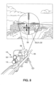
- FIG. 8 depicts an example of an embodiment of a viewer 10 mounted to a weapon such as a sniper rifle, including a variable magnification sniper sight or scope as the direct viewing optics 12, such as a 3.5 - 15 x 50 mm sniper sight.
- a view or image field 50 is also represented, showing real-world images 51 and an existing fixed reticle 52 seen through the direct viewing optics 12, as well as overlayed images 54 from the active display overlay unit 32, which can include an overlay reticle.
- a sniper sight, sighting device or apparatus 56 can also be mounted to the rifle 55 for measuring all relevant physical phenomena that can influence ballistic trajectory and calculate and display the offset aim point and confidence metric in the scope or direct viewing optics 12.
- the sighting device 56 can provide the ability to see the aim point on the target in both day or night, and can enable rapid target identification, weapon alignment, and measurement of range to target and crosswind profile.
- the sighting device 56 can be in communication with the active display overlay unit 32 for displaying images 54 in the image field 50, and can be mounted to the weapon 55 or can be separate. Some embodiments of sighting devices 56 can be positioned in front of the direct viewing optics 12.
- the embodiment of the active display overlay unit 32 in FIG. 8 can include a housing, housing portion, or cover 31 for housing and positioning the beam combiner 36 along viewing optical axis A, between lens assemblies 24 and 20, and secured to housing portions 33 and 35.
- the backlight/display assembly 34 can be positioned within housing 31 adjacent to or against one side of the beam combiner 36, and the display optical axis B can be at a 90° or right angle to viewing optical axis A.
- the display electronics 40 can be housed within housing 31 at a position spaced apart from another side of the beam combiner 36. This can incorporate the active display overlay unit 32 within direct viewing optics 12 such as a rifle scope, while minimizing any increases in size of the scope.
- the embodiment of the backlight/display assembly 34 in FIG. 9 can be generally rectangular in shape. Housing portions 60d and 60c can be secured to respective housing portions 60c and 60b, by insertion of locking protrusions 64 into recesses 66.
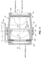
- the active display 46 can be a 640 x 480 monochrome display and the light source 42 can be a large area LED with a first or integrated lens 42a.
- the integrated lens 42a can have a generally hemispherical shape with a generally spherical front face and can collect maximum available light generated from the light source 42 and direct the light 68 to a second, illumination, or condenser lens 44, positioned between the light source 42 and the active display 46, all along display optical axis B.
- the condenser lens 44 can have a generally flat rear face or surface facing integrated lens 42, and a generally spherical front face with a larger radius than on the integrated lens 42a for concentrating light 68 received from integrated lens 42a onto active display 46 in an efficient manner.
- the first lens 42a is shaped to collect a maximum amount of light 68 available from light source 42, and the second lens is shaped and positioned to collect and direct the received light 68 onto active display 46 in a manner that provides uniform maximum brightness across the active display 46.
- the front face of the integrated lens 42a can be spaced from the rear face of condenser lens 44 by a distance d 3 , for example about 4 mm, and the front face of condenser lens 44 can be spaced from the rear face of active display 46 by a distance d 4 , for example about 2 mm.
- the light source 42 can be positioned within housing portion 60c, the condenser lens 44 can be positioned within housing portion 60b, and the active matrix 46 can be positioned within housing portion 60a, all secured along display optical axis B.
- This backlight/display assembly 34 with the two stage lens arrangement can have a very high brightness to power efficiency, with a monochrome luminance of at least 17130 cd/m2 (5000 fL) or greater to the ocular of the host system at 332 mW, and can have about a 300:1 or greater contrast.
- a 17130 cd/m2 (5000 fL) or greater luminance at 332 mW can provide a luminance to power cd/m2 :mW ratio of at least 51:1 (fL:mW ratio of at least 15:1) or greater.
- Such luminance provided to the viewing optical axis A can allow the overlayed images 54 to be daytime viewable, while being power efficient.
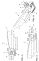
- FIG. 12 depicts an example of an embodiment of a viewer 10 attached to a weapon, gun or rifle 55, in which the direct viewing optics 12 is a 3.5 x 35 ACOG sight (Advanced Combat Optical Gunsight) or scope, which can be fixed magnification.
- the viewer 10 can include the backlight/display assembly 34 seen in FIGS. 10 and 11 , and can have a 640 x 480 monochrome active display 46.
- the backlight/display assembly 34 can be part of an active display overlay unit 32 that can provide daytime viewable images 54 such as an overlay reticle system and can provide an image field such as shown and described for FIG. 4 .
- the backlight/display assembly 34 can provide a monochrome luminance of at least 17130 cd/m 2 (5000 fL) or greater to the ocular of the host system at 332 mW, and can have about a 1,000,000:1 dimming range.
- a 17130 cd/m2 (5000 fL) or greater luminance at 332 mW can provide a luminance to power cd/m2 : mW ratio of at least 51:1 (fL:mW ratio of at least 15:1) or greater.
- Some embodiments can provide monochrome luminance at such levels to the eye.
- the backlight/display assembly 34 and the beam combiner 36 of the active display overlay unit 32 of FIG. 12 can be horizontally aligned along display optical axis B at a right angle to viewing optical axis A.
- the beam combiner 36 can have a coating 36c with 50/50 non-polarizing coating, or implemented with a coating customized for red LED wavelength and s-polarization.
- the display electronics 40 can be positioned offset from and under the beam combiner 36 and backlight/display assembly 34.
- the beam combiner 36 of the active display overlay unit of FIG. 12 can be cube shaped and formed of two optical members or elements 36a and 36b combined or bonded together.
- the coating 36c can be formed by coating one or both bonded hypotenuse surfaces with an optical thin film coating so that photopically weighted transmission (450 nm to 650 nm) for non-polarized light is greater than 90% for angles of incidence of 45° +/- 8°. Reflectance (615 nm to 650 nm) for s-polarized light is greater than 90% for angles of incidence of 45° +/- 8°.
- Anti-reflection coating can be applied to surfaces such that photopically weighted reflectance (450 nm to 650 nm) for non-polarized light is less than 0.5% for angles of incidence of 0° +/- 10°. Anti-reflection coating can be applied to surfaces such that photopically weighted reflectance (615 nm to 650 nm) for non-polarized light is less than 0.5% for angles of incidence of 0° +/- 10°. This can form a customized red s-polarized reflective coating for the beam combiner 36. It is understood that different coatings can be applied to beam combiner 36 to meet the requirements of different embodiments in the present invention, shown and described.
- the direct viewing optics 12, such as in a weapon sight such as a rifle or gun sight or scope can have well defined and limited angles of incidence (AOI) at the image plane, and can have small cone angles of illumination at the image plane less than about +/- 10°, such as +/- 4°.
- Embodiments of the active display overlay unit 32 can be configured to provide illumination that matches, or approximately or substantially matches the angles of incidence of the direct viewing optics 12 at the image plane to obtain optimum simultaneous viewing at the eyepiece 25 of images from both optical axes A and B, for images 51 viewed by the direct viewing optics 12, and for images 54 generated by active display overlay unit 32.
- the backlight/display assembly 34 for the direct viewing optics 12 of FIG. 17 can have a light source 42, such as an LED illuminating the active display 46, which can be an LCD such as shown and described with respect to FIG. 5 .
- the backlight/display assembly 34 can be similar to that in FIG. 7 .
- the LED light source 42 can be positioned a distance d 5 from the active display 46, and can directly illuminate the active display 46, with light 68 to produce a very high luminance of the surface of the active display 46 to obtain a high luminance of images 54 in the eyepiece 25 of the direct viewing optics 12, while matching, or approximately or substantially matching the images of incidence and cone angles at the image plane of the direct viewing optics 12.
- the lens 44 can be in front of and adjacent to or next to the active display 46 and receives light 68 from light source 42 and directs the light 68 onto the active display 46 in a manner to obtain a high luminance of images 54 in the eyepiece 25 of the direct viewing optics 12, while matching, or approximately or substantially matching the angles of incidence and cone angles at the image plane of the direct viewing optics 12.
- the size and location of the light source 42 relative to the active display 46 and the lens 44 can be selected to provide desired angles of incidence and cone angles of illumination or light 68 at the active display 46.
- the light source 42 can be a large area LED with dimensions of about 3 x 3 mm at a distance d 6 of about 8 mm and provide about a +/-10° of cone angle output from the image plane of the active display 46.
- the light source 42 can be a medium area LED of about 1 ⁇ 1 mm at a distance d 6 of about 8 mm and provide about a +/- 3.3° of cone angle output from the image plane of the active display 46.
- the light source 42 can be a small area LED of about .5 x .5 mm at a distance of about 8 mm and provide about a +/- 1.6° of cone angle output from the image plane of the active display 46.
- cone angles of +/- 10° or less can be achieved to match, or approximately or substantially match the direct viewing optics 12.
- the angles of incidence can be about halfway between or bisect the cone angles, as shown.
- the lens 44 and its design can allow angles of incidence of illumination at the active display to match, or approximately or substantially match viewing optics that are divergent or convergent independent of light source 42 distance.
- the light source 42 can include an integrated lens 42a.
- the designs of the backlight/display assemblies 34 and active display overlay unit 32 shown and described can provide high luminance images 54 to be produced in a manner that can be seen simultaneously with images viewed with the direct viewing optics, even during the day.
- a beam combiner or other means to optically combine the images can be aligned with the display along the display optical axis, and positioned along the viewing optical axis of the viewing optics for directing the images from the display onto the viewing optical axis for combining with the field of view that is viewed by the viewing optics with those of the display in an overlaid manner.
- the display optical axis of the active display overlay unit can be at any angle to the viewing optical axis of the viewing optics, and can include right angles.
- the active display overlay unit can utilize a reflective display element, a transmissive display element or an emissive display element, which can be an active display. It can further include an LED backlight for illuminating a transmissive display or active display with LED illumination.
- a lens arrangement can focus or concentrate the LED illumination onto the transmissive display or active display and into the viewing area.
- Electronics can control the display, the display format and content as well as the relative position of imagery and symbology with respect to the viewing optical axis.
- the display can provide text, alpha-numerics, symbology and/or video imagery including an active target reticle, range and wind information, GPS and compass information, target ID, and/or external sensor information.
- the display overlay unit provides at least one of full-color and monochrome luminance of at least about 4111. 2 cd/m2 (1200 fL) to the ocular of the host system with a luminance to power cd/m2:mW ratio of at least 20:1 (fL:mW ratio of at least about 6:1) or greater, for example, full color luminance of at least about 4111.2 cd/m2 (1200 fL) or greater at about 200 mW, or monochrome luminance of at least about 17130 cd/m2 (5000 fL) or greater at about 332 mW.
- the dimming range and spectral content or specific wavelength of imagery of the display can be such that the display can be dimmed to a level allowing the user to view the overlaid image and real-world scene through the viewing optics with image intensifier (night vision goggle) based products or thermal imaging devices.
- image intensifier night vision goggle
- a housing can be included for containing the viewing optics and the display overlay unit.
- the complete unit can be mounted as an external accessory device which is then coupled to the real-world optical viewing device or integrated into a larger system such as a fire-control, target locator/designator or weapon sight system.
- the unit can be packaged as an integral part of the real-world viewing system.
- the active overlay display function can be an add-on accessory device to the real-world viewing system.
- the accessory device can contain features both mechanically and electrically to boresight (align) the overlaid display from the display overlay unit to the optical axis of the real-world viewer.
- the viewing optical axis A can be folded and the display optical axis B can be aligned with one portion of the viewing optical axis A.
Landscapes
- Physics & Mathematics (AREA)
- Optics & Photonics (AREA)
- General Physics & Mathematics (AREA)
- Engineering & Computer Science (AREA)
- General Engineering & Computer Science (AREA)
- Astronomy & Astrophysics (AREA)
- Telescopes (AREA)
- Aiming, Guidance, Guns With A Light Source, Armor, Camouflage, And Targets (AREA)
Claims (14)
- Viseur du monde réel (10) comprenant :une optique de visualisation (12) positionnée le long d'un axe optique de visualisation (A) pour visualiser un champ de vision du monde réel ; etune unité de superposition d'affichage actif (32) couplée optiquement à l'axe optique de visualisation (A) de l'optique de visualisation (12), pour générer des images (54) et diriger les images (54) le long de l'axe optique de visualisation (A) de l'optique de visualisation (12) pour une visualisation superposée simultanée des images (54) et de la scène du monde réel telle que visualisée dans le champ de vision à travers l'optique de visualisation (12), l'unité de superposition d'affichage actif (32) fournissant une luminance d'au moins 4 111,51 cd/m2 (1 200 fL) à l'oculaire (24) du système hôte avec un rapport de luminance à l'oculaire du système hôte sur la consommation d'énergie cd/m2:mW d'au moins 20:1 (rapport fL:mW d'au moins 6:1) ou plus, dans lequel l'unité de superposition d'affichage actif (32) comprend :un affichage transmissif actif (46) pour générer les images (54) le long d'un axe optique d'affichage (B) ;un rétroéclairage à LED (42) pour éclairer l'affichage transmissif actif (46), dans lequel le rétroéclairage à LED (42) fournit un angle de cône d'éclairage au niveau de l'affichage transmissif actif qui correspond sensiblement à un angle de cône de visualisation de l'optique de visualisation (12), l'angle de cône étant d'environ +/- 10° ou moins ; etun combinateur de faisceaux (36) aligné avec l'affichage transmissif actif (46) le long de l'axe optique d'affichage (B) et positionné le long de l'axe optique de visualisation (A) de l'optique de visualisation (12) pour diriger les images (54) depuis l'affichage transmissif actif (46) sur l'axe optique de visualisation (A) pour les combiner avec le champ de vision qui est visualisé par l'optique de visualisation (12) d'une façon superposée.
- Viseur selon la revendication 1, dans lequel le viseur est au moins l'un parmi un viseur d'arme, un accessoire complémentaire à un viseur d'arme, un viseur de fusil, un accessoire complémentaire à un viseur de fusil, un système de surveillance, un accessoire complémentaire à un système de surveillance, un système de conduite de tir, un accessoire complémentaire à un système de conduite de tir, un localisateur et désignateur de cible laser, un accessoire complémentaire à un localisateur et désignateur de cible laser, un affichage monté sur la tête ou sur un casque, un accessoire complémentaire à un affichage monté sur la tête ou sur un casque, un télémètre ou un accessoire complémentaire à un télémètre.
- Viseur selon la revendication 1, dans lequel l'optique de visualisation (12) est une optique de visualisation directe positionnée le long d'un axe optique de visualisation longitudinal (A).
- Viseur selon la revendication 3, dans lequel l'axe optique d'affichage (B) de l'unité de superposition d'affichage actif (32) est à un angle par rapport à l'axe optique de visualisation (A) de l'optique de visualisation (12).
- Viseur selon la revendication 1, comprenant en outre un agencement de lentilles (42a/44) qui comprend une lentille intégrée (42a) intégrée dans le rétroéclairage à LED (42) et une lentille de condensation (44) positionnée entre la lentille intégrée et l'affichage transmissif actif (46).
- Viseur selon la revendication 5, dans lequel l'unité de superposition d'affichage actif (32) à 332 mW est capable de fournir une luminance monochrome d'au moins 17 131,29 cd/m2 (5 000 fL) à l'oculaire (24) du système hôte avec un rapport de la luminance sur la puissance cd/m2:mW d'au moins 51:1 (fL:mW rapport d'au moins 15:1) ou plus.
- Viseur selon la revendication 3, comprenant en outre une électronique de commande de l'affichage actif et l'affichage actif peut fournir des images pour au moins un parmi un réticule de cible actif, des informations de portée et de vent, des informations GPS et de boussole, un identifiant ID de cible et/ou des informations de capteur externe.
- Viseur selon la revendication 5, comprenant en outre un boîtier (14/60) destiné à contenir l'optique de visualisation (12) et l'unité de superposition d'affichage actif (32).
- Viseur selon la revendication 2, dans lequel le champ de vision comporte des éléments de connaissance de la cible ou de la situation.
- Viseur selon la revendication 3, dans lequel l'unité de superposition d'affichage actif (32) :est configurée pour commander la luminosité pour permettre une visualisation dans des conditions ambiantes allant de la pleine lumière du soleil à la lumière des étoiles couverte, ouest capable de produire une longueur d'onde spécifique d'imagerie et une gradation pour visualiser le monde réel et les images de l'unité d'affichage de superposition actif à l'aide d'un dispositif de vision nocturne à intensificateur d'image ou d'un dispositif d'imagerie thermique, oufournit au moins une image superposée monochrome, multicolore et/ou en couleur, à deux niveaux et/ou à niveaux de gris complets.
- Viseur selon la revendication 2, comprenant en outre des capacités de visée mécaniques et électriques sur l'axe optique de visualisation du monde réel.
- Viseur selon la revendication 1, comprenant en outre des moyens (14/60) pour emballer l'unité de superposition d'affichage actif (32) en tant que partie intégrée du viseur du monde réel.
- Viseur selon la revendication 1, dans lequel l'unité de superposition d'affichage actif (32) est un dispositif complémentaire accessoire au viseur du monde réel.
- Procédé de visualisation avec un viseur du monde réel (10) comprenant :la visualisation d'un champ de vision du monde réel avec une optique de visualisation (12) positionnée le long d'un axe optique de visualisation (A) ; etla visualisation simultanée d'images (54) générées par une unité de superposition d'affichage actif (32) couplée optiquement à l'axe optique de visualisation (A) de l'optique de visualisation (12), les images (54) étant dirigées le long de l'axe optique de visualisation (A) de l'optique de visualisation (12) pour une visualisation superposée simultanée des images (54) et de la scène du monde réel telle que visualisée dans le champ de vision à travers l'optique de visualisation (12), l'unité de superposition d'affichage actif (32) fournissant une luminance d'au moins 4 111,51 cd/m2 (1 200 fL) à l'oculaire (24) du système hôte avec un rapport de luminance à l'oculaire du système hôte sur la consommation d'énergie cd/m2:mW d'au moins 20:1 (rapport fL:mW d'au moins 6:1) ou plus, dans lequel l'unité de superposition d'affichage actif (32) comprend :un affichage transmissif actif (46) pour générer les images (54) le long d'un axe optique d'affichage (B) ;un rétroéclairage à LED (42) pour éclairer l'affichage transmissif actif (46), dans lequel le rétroéclairage à LED (42) fournit un angle de cône d'éclairage au niveau de l'affichage transmissif actif qui correspond sensiblement à un angle de cône de visualisation de l'optique de visualisation (12), l'angle de cône étant d'environ +/- 10° ou moins ; etun combinateur de faisceaux (36) aligné avec l'affichage transmissif actif (46) le long de l'axe optique d'affichage (B) et positionné le long de l'axe optique de visualisation (A) de l'optique de visualisation (12) pour diriger les images (54) depuis l'affichage transmissif actif (46) sur l'axe optique de visualisation (A) pour les combiner avec le champ de vision qui est visualisé par l'optique de visualisation (12) d'une façon superposée.
Applications Claiming Priority (3)
| Application Number | Priority Date | Filing Date | Title |
|---|---|---|---|
| US201261625808P | 2012-04-18 | 2012-04-18 | |
| US13/800,843 US9389425B2 (en) | 2012-04-18 | 2013-03-13 | Viewer with display overlay |
| PCT/US2013/036400 WO2013158495A1 (fr) | 2012-04-18 | 2013-04-12 | Visionneur avec superposition d'affichage |
Publications (2)
| Publication Number | Publication Date |
|---|---|
| EP2836870A1 EP2836870A1 (fr) | 2015-02-18 |
| EP2836870B1 true EP2836870B1 (fr) | 2024-10-09 |
Family
ID=49379874
Family Applications (1)
| Application Number | Title | Priority Date | Filing Date |
|---|---|---|---|
| EP13719199.5A Active EP2836870B1 (fr) | 2012-04-18 | 2013-04-12 | Visionneur avec superposition d'affichage |
Country Status (7)
| Country | Link |
|---|---|
| US (1) | US9389425B2 (fr) |
| EP (1) | EP2836870B1 (fr) |
| JP (1) | JP6283020B2 (fr) |
| KR (1) | KR101972099B1 (fr) |
| CN (1) | CN104395810B (fr) |
| SG (1) | SG11201406740XA (fr) |
| WO (1) | WO2013158495A1 (fr) |
Families Citing this family (41)
| Publication number | Priority date | Publication date | Assignee | Title |
|---|---|---|---|---|
| US9389425B2 (en) | 2012-04-18 | 2016-07-12 | Kopin Corporation | Viewer with display overlay |
| US9323061B2 (en) | 2012-04-18 | 2016-04-26 | Kopin Corporation | Viewer with display overlay |
| US20140267389A1 (en) * | 2013-03-14 | 2014-09-18 | Exelis Inc. | Night Vision Display Overlaid with Sensor Data |
| DE102013102826B4 (de) * | 2013-03-19 | 2016-10-06 | Schmidt & Bender Gmbh & Co. Kg | Zielfernrohr |
| US10480901B2 (en) | 2013-07-30 | 2019-11-19 | Gunwerks, Llc | Riflescope with feedback display and related methods |
| JP6248473B2 (ja) * | 2013-08-28 | 2017-12-20 | 日本精機株式会社 | ヘッドアップディスプレイ装置 |
| US9335124B2 (en) | 2013-11-18 | 2016-05-10 | Cubic Corporation | Compact riflescope display adapter |
| JP6198599B2 (ja) * | 2013-12-16 | 2017-09-20 | キヤノン株式会社 | 撮像装置及びその制御方法 |
| US10274286B2 (en) | 2014-11-17 | 2019-04-30 | Cubic Corporation | Rifle scope targeting display adapter |
| US10443984B2 (en) | 2014-11-17 | 2019-10-15 | Cubic Corporation | Low-cost rifle scope display adapter |
| US9791244B2 (en) | 2014-11-17 | 2017-10-17 | Cubic Corporation | Rifle scope targeting display adapter mount |
| US9851578B2 (en) * | 2015-01-23 | 2017-12-26 | Lasermax Inc | Adaptive particle projection path indicator |
| CA2977824C (fr) * | 2015-03-24 | 2023-05-23 | Cubic Corporation | Adaptateur d'affichage de cible destine a une lunette de visee pour arme d'epaule |
| CN106152876B (zh) * | 2015-04-15 | 2018-06-19 | 信泰光学(深圳)有限公司 | 弹道预测系统 |
| US10146051B2 (en) * | 2015-08-28 | 2018-12-04 | Jsc Yukon Advanced Optics Worldwide | Precision adjustment of projected digital information within a daylight optical device |
| US10061112B1 (en) * | 2016-02-03 | 2018-08-28 | Opti-Logic Corporation | Optical accessory projection system |
| CN105806154B (zh) * | 2016-05-17 | 2017-12-29 | 珠海市敏夫光学仪器有限公司 | 瞄准镜组合式分划板组、瞄准镜光学成像系统以及棱镜倒像瞄准镜 |
| WO2017219275A1 (fr) * | 2016-06-22 | 2017-12-28 | 深圳市可凡研磨材料有限公司 | Télescope de visée |
| US9964805B2 (en) * | 2016-08-26 | 2018-05-08 | Laser Technology, Inc. | Backlighting technique for liquid crystal and other displays in electronic instruments |
| WO2018057872A1 (fr) | 2016-09-22 | 2018-03-29 | Lightforce USA, Inc., d/b/a/ Nightforce Optics, Inc. | Système de projection d'informations de ciblage optique pour des endoscopes de visée de système d'arme et systèmes associés |
| IL321694A (en) * | 2017-02-06 | 2025-08-01 | Sheltered Wings Inc D/B/A Vortex Optics | Optical sight with integral display system |
| US10042154B1 (en) | 2017-02-06 | 2018-08-07 | Bushnell Inc. | System and method for introducing display image into afocal optics device |
| EP3642554B1 (fr) | 2017-06-20 | 2024-05-01 | Lightforce USA, Inc., D/B/A/ Nightforce Optics | Montage sur lunette de visée avec concentrateur de connectivité électrique |
| WO2019060858A1 (fr) * | 2017-09-22 | 2019-03-28 | Intellisense Systems, Inc. | Systèmes et procédés d'imageur infrarouge à longue portée |
| US11675180B2 (en) | 2018-01-12 | 2023-06-13 | Sheltered Wings, Inc. | Viewing optic with an integrated display system |
| MY207434A (en) | 2018-03-20 | 2025-02-26 | Sheltered Wings Inc D/B/A Vortex Optics | Viewing optic with a base having a light module |
| US11480781B2 (en) | 2018-04-20 | 2022-10-25 | Sheltered Wings, Inc. | Viewing optic with direct active reticle targeting |
| US11526935B1 (en) | 2018-06-13 | 2022-12-13 | Wells Fargo Bank, N.A. | Facilitating audit related activities |
| EP4220069A1 (fr) * | 2018-08-08 | 2023-08-02 | Sheltered Wings, Inc. D/b/a/ Vortex Optics | Système d'affichage pour optique de visualisation |
| KR102772542B1 (ko) * | 2018-08-15 | 2025-02-24 | 마수피얼 홀딩스 아이엔시. | 디렉트뷰 옵틱 |
| WO2020146989A1 (fr) * | 2019-01-14 | 2020-07-23 | 深圳市瑞尔幸电子有限公司 | Dispositif de visée |
| CA3127091A1 (fr) | 2019-01-18 | 2020-07-23 | Sheltered Wings, Inc. D/B/A Vortex Optics | Optique de visualisation avec systeme de compteur de coups |
| US11287638B2 (en) | 2019-08-20 | 2022-03-29 | Francesco E. DeAngelis | Reflex sight with superluminescent micro-display, dynamic reticle, and metadata overlay |
| US11473874B2 (en) | 2020-02-19 | 2022-10-18 | Maztech Industries, LLC | Weapon system with multi-function single-view scope |
| US12468168B2 (en) | 2020-05-05 | 2025-11-11 | Sheltered Wings, Inc. | Reticle for a viewing optic |
| KR20230019426A (ko) | 2020-05-05 | 2023-02-08 | 쉘터드 윙스, 인크. 디/비/에이 보텍스 옵틱스 | 인에이블러 인터페이스를 구비하는 시야 광학체 |
| US11428503B1 (en) | 2021-04-02 | 2022-08-30 | Trijicon, Inc. | Digital aiming system for weapon |
| US11768055B2 (en) | 2021-05-12 | 2023-09-26 | Trijicon, Inc. | Ballistic drop and ranging system for a weapon |
| WO2023023200A1 (fr) | 2021-08-18 | 2023-02-23 | Maztech Industries, LLC | Systèmes de visée d'arme |
| US12481148B2 (en) | 2021-12-08 | 2025-11-25 | Trijicon, Inc. | Optical sight |
| AU2023259144A1 (en) | 2022-04-25 | 2024-10-31 | Sheltered Wings, Inc. D/B/A Vortex Optics | Imaging enabler for a viewing optic |
Citations (1)
| Publication number | Priority date | Publication date | Assignee | Title |
|---|---|---|---|---|
| DE102009011908B4 (de) * | 2009-03-05 | 2021-12-09 | Bayerische Motoren Werke Aktiengesellschaft | Head-up-Display und Fahrzeug |
Family Cites Families (39)
| Publication number | Priority date | Publication date | Assignee | Title |
|---|---|---|---|---|
| DE3002580C2 (de) | 1980-01-25 | 1987-07-09 | Messerschmitt-Bölkow-Blohm GmbH, 8000 München | Optisches Zielgerät |
| US4949089A (en) | 1989-08-24 | 1990-08-14 | General Dynamics Corporation | Portable target locator system |
| GB2238627B (en) | 1989-11-29 | 1994-04-06 | Yazaki Corp | Display apparatus |
| US5103254A (en) | 1990-05-29 | 1992-04-07 | Eastman Kodak Company | Camera with subject highlighting and motion detection |
| US5311203A (en) | 1993-01-29 | 1994-05-10 | Norton M Kent | Viewing and display apparatus |
| JP3411953B2 (ja) | 1996-04-24 | 2003-06-03 | シャープ株式会社 | 光学装置および該光学装置を用いた頭部搭載型ディスプレイ |
| FR2760831B1 (fr) | 1997-03-12 | 1999-05-28 | Marie Christine Bricard | Lunette de tir pour arme individuelle a pointage et mise au point automatique |
| SE516715C2 (sv) | 1999-05-26 | 2002-02-19 | Ericsson Telefon Ab L M | Display för huvudmontering |
| US6516551B2 (en) | 2000-12-27 | 2003-02-11 | American Technologies Network Corporation | Optical sight with switchable reticle |
| US7040794B2 (en) * | 2001-07-12 | 2006-05-09 | Northrop Grumman Corporation | Programmable multi-color backlight for a liquid crystal display |
| US20030132860A1 (en) * | 2001-09-21 | 2003-07-17 | Honeywell International, Inc. | Interface for visual cueing and control for tactical flightpath management |
| JP4364047B2 (ja) * | 2004-04-14 | 2009-11-11 | オリンパス株式会社 | 表示装置、撮像装置 |
| CN100350792C (zh) * | 2004-04-14 | 2007-11-21 | 奥林巴斯株式会社 | 摄像装置 |
| CH697492B1 (de) | 2004-04-17 | 2008-11-14 | Vectronix Ag | Verfahren zum Schätzen der Genauigkeit azimutaler Ausrichtungen, Verfahren zum Bereitstellen einer azimutalen Ausrichtung eines tragbaren Zielgeräts und eines geschätzten Wertes deren Genauigkeit und tragbares Zielgerät. |
| US20050250085A1 (en) | 2004-05-07 | 2005-11-10 | Yamcon, Inc. | Viewing and display apparatus |
| WO2005111693A1 (fr) | 2004-05-17 | 2005-11-24 | Olympus Corporation | Dispositif de lunettes de visualisation d’image |
| US7196329B1 (en) * | 2004-06-17 | 2007-03-27 | Rockwell Collins, Inc. | Head-down enhanced vision system |
| US7307793B2 (en) | 2004-07-02 | 2007-12-11 | Insight Technology, Inc. | Fusion night vision system |
| US7239377B2 (en) | 2004-10-13 | 2007-07-03 | Bushnell Performance Optics | Method, device, and computer program for determining a range to a target |
| US7319557B2 (en) * | 2005-01-26 | 2008-01-15 | Eotech Acquisition Corporation | Fused thermal and direct view aiming sight |
| US7333270B1 (en) | 2005-06-10 | 2008-02-19 | Omnitech Partners | Dual band night vision device |
| TWI429875B (zh) | 2005-11-01 | 2014-03-11 | Leupold & Stevens Inc | 用於傾斜射擊之彈道測距方法及系統 |
| US7295296B1 (en) | 2005-12-15 | 2007-11-13 | L-3 Communications Integrated Systems L.P. | Portable target locator apparatus and method of use |
| US7805020B2 (en) | 2006-07-25 | 2010-09-28 | Itt Manufacturing Enterprises, Inc. | Motion compensated image registration for overlaid/fused video |
| WO2008088691A2 (fr) | 2007-01-12 | 2008-07-24 | Kopin Corporation | Dispositif d'affichage monoculaire |
| JP4301304B2 (ja) | 2007-02-13 | 2009-07-22 | セイコーエプソン株式会社 | 画像表示装置 |
| GB2486368A (en) * | 2007-05-22 | 2012-06-13 | Trijicon Inc | Optical sight |
| US8051597B1 (en) | 2007-06-14 | 2011-11-08 | Cubic Corporation | Scout sniper observation scope |
| CA2712059A1 (fr) | 2008-01-22 | 2009-07-30 | The Arizona Board Of Regents On Behalf Of The University Of Arizona | Visiocasque de projection utilisant des micro-dispositifs d'affichage reflechissants |
| US7905046B2 (en) | 2008-02-15 | 2011-03-15 | Thomas D. Smith, III | System and method for determining target range and coordinating team fire |
| US8081298B1 (en) | 2008-07-24 | 2011-12-20 | Bushnell, Inc. | Handheld rangefinder operable to determine hold-over ballistic information |
| KR101064026B1 (ko) * | 2009-02-17 | 2011-09-08 | 엘지이노텍 주식회사 | 발광 디바이스 패키지 및 그 제조방법 |
| US8166698B2 (en) * | 2009-08-13 | 2012-05-01 | Roni Raviv | Reflex sight for weapon |
| US8378279B2 (en) | 2009-11-23 | 2013-02-19 | Fraser-Volpe, Llc | Portable integrated laser optical target tracker |
| US8836888B2 (en) | 2009-12-15 | 2014-09-16 | Gentex Corporation | Modular light source/electronics and automotive rearview assemblies using the same |
| US9128281B2 (en) | 2010-09-14 | 2015-09-08 | Microsoft Technology Licensing, Llc | Eyepiece with uniformly illuminated reflective display |
| US20120097741A1 (en) | 2010-10-25 | 2012-04-26 | Karcher Philip B | Weapon sight |
| US9389425B2 (en) | 2012-04-18 | 2016-07-12 | Kopin Corporation | Viewer with display overlay |
| US9323061B2 (en) | 2012-04-18 | 2016-04-26 | Kopin Corporation | Viewer with display overlay |
-
2013
- 2013-03-13 US US13/800,843 patent/US9389425B2/en active Active
- 2013-04-12 JP JP2015507072A patent/JP6283020B2/ja active Active
- 2013-04-12 WO PCT/US2013/036400 patent/WO2013158495A1/fr not_active Ceased
- 2013-04-12 CN CN201380029122.7A patent/CN104395810B/zh active Active
- 2013-04-12 SG SG11201406740XA patent/SG11201406740XA/en unknown
- 2013-04-12 EP EP13719199.5A patent/EP2836870B1/fr active Active
- 2013-04-12 KR KR1020147032199A patent/KR101972099B1/ko active Active
Patent Citations (1)
| Publication number | Priority date | Publication date | Assignee | Title |
|---|---|---|---|---|
| DE102009011908B4 (de) * | 2009-03-05 | 2021-12-09 | Bayerische Motoren Werke Aktiengesellschaft | Head-up-Display und Fahrzeug |
Non-Patent Citations (1)
| Title |
|---|
| ANONYMOUS: "Luminance - Wikipedia, the free encyclopedia", 14 February 2012 (2012-02-14), pages 1 - 2, XP055975996, Retrieved from the Internet <URL:https://web.archive.org/web/20120214213438/https://en.wikipedia.org/wiki/Luminance> [retrieved on 20221028] * |
Also Published As
| Publication number | Publication date |
|---|---|
| JP6283020B2 (ja) | 2018-02-21 |
| KR20150023265A (ko) | 2015-03-05 |
| WO2013158495A1 (fr) | 2013-10-24 |
| SG11201406740XA (en) | 2014-11-27 |
| CN104395810A (zh) | 2015-03-04 |
| KR101972099B1 (ko) | 2019-04-24 |
| JP2015520866A (ja) | 2015-07-23 |
| EP2836870A1 (fr) | 2015-02-18 |
| CN104395810B (zh) | 2016-11-23 |
| US9389425B2 (en) | 2016-07-12 |
| US20130279013A1 (en) | 2013-10-24 |
Similar Documents
| Publication | Publication Date | Title |
|---|---|---|
| EP2836870B1 (fr) | Visionneur avec superposition d'affichage | |
| US9323061B2 (en) | Viewer with display overlay | |
| JP7393951B2 (ja) | 照光照準器及び熱撮像カメラを有する照準スコープ | |
| US9335124B2 (en) | Compact riflescope display adapter | |
| EP1798587B1 (fr) | Afficheur tête haute | |
| US5497266A (en) | Telescopic day and night sight | |
| US9200869B2 (en) | Composite optical device for sighting targets and measuring distances | |
| JP2015520866A5 (fr) | ||
| WO2012058453A2 (fr) | Système de visée | |
| US10642038B1 (en) | Waveguide based fused vision system for a helmet mounted or head worn application | |
| US8988648B2 (en) | Integrated image erector and through-sight information display for telescope or other optical device | |
| CN100388047C (zh) | 组合目视装置 | |
| US20240027168A1 (en) | Protective cover for an optic device | |
| US9426389B1 (en) | Second imaging device adaptable for use with first imaging device and method for using same | |
| US8416493B1 (en) | Optical systems | |
| US12613078B2 (en) | Imaging apparatus with thermal augmentation | |
| WO2011045759A1 (fr) | Séparateur d'images pour dispositif de visée d'arme à feu | |
| IL193091A (en) | Reflex sight for weapon | |
| HK40023951A (en) | Aiming scope with illuminated sights and thermal imaging camera | |
| Foote | Design impacts to the HMD when used as the primary display | |
| CN121844243A (zh) | 具有相机功能的放大镜 | |
| HK1097606B (en) | Modular visualization devices |
Legal Events
| Date | Code | Title | Description |
|---|---|---|---|
| PUAI | Public reference made under article 153(3) epc to a published international application that has entered the european phase |
Free format text: ORIGINAL CODE: 0009012 |
|
| 17P | Request for examination filed |
Effective date: 20141111 |
|
| AK | Designated contracting states |
Kind code of ref document: A1 Designated state(s): AL AT BE BG CH CY CZ DE DK EE ES FI FR GB GR HR HU IE IS IT LI LT LU LV MC MK MT NL NO PL PT RO RS SE SI SK SM TR |
|
| AX | Request for extension of the european patent |
Extension state: BA ME |
|
| DAX | Request for extension of the european patent (deleted) | ||
| STAA | Information on the status of an ep patent application or granted ep patent |
Free format text: STATUS: EXAMINATION IS IN PROGRESS |
|
| 17Q | First examination report despatched |
Effective date: 20181015 |
|
| REG | Reference to a national code |
Ref country code: DE Ref legal event code: R079 Free format text: PREVIOUS MAIN CLASS: G02B0023100000 Ipc: G02B0027010000 Ref country code: DE Ref legal event code: R079 Ref document number: 602013086160 Country of ref document: DE Free format text: PREVIOUS MAIN CLASS: G02B0023100000 Ipc: G02B0027010000 |
|
| GRAP | Despatch of communication of intention to grant a patent |
Free format text: ORIGINAL CODE: EPIDOSNIGR1 |
|
| STAA | Information on the status of an ep patent application or granted ep patent |
Free format text: STATUS: GRANT OF PATENT IS INTENDED |
|
| RIC1 | Information provided on ipc code assigned before grant |
Ipc: F41G 1/38 20060101ALI20240415BHEP Ipc: F41G 1/00 20060101ALI20240415BHEP Ipc: G02B 23/10 20060101ALI20240415BHEP Ipc: G02B 27/01 20060101AFI20240415BHEP |
|
| INTG | Intention to grant announced |
Effective date: 20240502 |
|
| GRAS | Grant fee paid |
Free format text: ORIGINAL CODE: EPIDOSNIGR3 |
|
| GRAA | (expected) grant |
Free format text: ORIGINAL CODE: 0009210 |
|
| STAA | Information on the status of an ep patent application or granted ep patent |
Free format text: STATUS: THE PATENT HAS BEEN GRANTED |
|
| AK | Designated contracting states |
Kind code of ref document: B1 Designated state(s): AL AT BE BG CH CY CZ DE DK EE ES FI FR GB GR HR HU IE IS IT LI LT LU LV MC MK MT NL NO PL PT RO RS SE SI SK SM TR |
|
| REG | Reference to a national code |
Ref country code: GB Ref legal event code: FG4D |
|
| REG | Reference to a national code |
Ref country code: CH Ref legal event code: EP |
|
| REG | Reference to a national code |
Ref country code: DE Ref legal event code: R096 Ref document number: 602013086160 Country of ref document: DE |
|
| REG | Reference to a national code |
Ref country code: IE Ref legal event code: FG4D |
|
| REG | Reference to a national code |
Ref country code: LT Ref legal event code: MG9D |
|
| REG | Reference to a national code |
Ref country code: NL Ref legal event code: MP Effective date: 20241009 |
|
| REG | Reference to a national code |
Ref country code: AT Ref legal event code: MK05 Ref document number: 1731205 Country of ref document: AT Kind code of ref document: T Effective date: 20241009 |
|
| PG25 | Lapsed in a contracting state [announced via postgrant information from national office to epo] |
Ref country code: NL Free format text: LAPSE BECAUSE OF FAILURE TO SUBMIT A TRANSLATION OF THE DESCRIPTION OR TO PAY THE FEE WITHIN THE PRESCRIBED TIME-LIMIT Effective date: 20241009 |
|
| PG25 | Lapsed in a contracting state [announced via postgrant information from national office to epo] |
Ref country code: NL Free format text: LAPSE BECAUSE OF FAILURE TO SUBMIT A TRANSLATION OF THE DESCRIPTION OR TO PAY THE FEE WITHIN THE PRESCRIBED TIME-LIMIT Effective date: 20241009 |
|
| PG25 | Lapsed in a contracting state [announced via postgrant information from national office to epo] |
Ref country code: IS Free format text: LAPSE BECAUSE OF FAILURE TO SUBMIT A TRANSLATION OF THE DESCRIPTION OR TO PAY THE FEE WITHIN THE PRESCRIBED TIME-LIMIT Effective date: 20250209 Ref country code: HR Free format text: LAPSE BECAUSE OF FAILURE TO SUBMIT A TRANSLATION OF THE DESCRIPTION OR TO PAY THE FEE WITHIN THE PRESCRIBED TIME-LIMIT Effective date: 20241009 Ref country code: PT Free format text: LAPSE BECAUSE OF FAILURE TO SUBMIT A TRANSLATION OF THE DESCRIPTION OR TO PAY THE FEE WITHIN THE PRESCRIBED TIME-LIMIT Effective date: 20250210 |
|
| PG25 | Lapsed in a contracting state [announced via postgrant information from national office to epo] |
Ref country code: FI Free format text: LAPSE BECAUSE OF FAILURE TO SUBMIT A TRANSLATION OF THE DESCRIPTION OR TO PAY THE FEE WITHIN THE PRESCRIBED TIME-LIMIT Effective date: 20241009 |
|
| PG25 | Lapsed in a contracting state [announced via postgrant information from national office to epo] |
Ref country code: BG Free format text: LAPSE BECAUSE OF FAILURE TO SUBMIT A TRANSLATION OF THE DESCRIPTION OR TO PAY THE FEE WITHIN THE PRESCRIBED TIME-LIMIT Effective date: 20241009 |
|
| PG25 | Lapsed in a contracting state [announced via postgrant information from national office to epo] |
Ref country code: ES Free format text: LAPSE BECAUSE OF FAILURE TO SUBMIT A TRANSLATION OF THE DESCRIPTION OR TO PAY THE FEE WITHIN THE PRESCRIBED TIME-LIMIT Effective date: 20241009 |
|
| PG25 | Lapsed in a contracting state [announced via postgrant information from national office to epo] |
Ref country code: NO Free format text: LAPSE BECAUSE OF FAILURE TO SUBMIT A TRANSLATION OF THE DESCRIPTION OR TO PAY THE FEE WITHIN THE PRESCRIBED TIME-LIMIT Effective date: 20250109 |
|
| PG25 | Lapsed in a contracting state [announced via postgrant information from national office to epo] |
Ref country code: LV Free format text: LAPSE BECAUSE OF FAILURE TO SUBMIT A TRANSLATION OF THE DESCRIPTION OR TO PAY THE FEE WITHIN THE PRESCRIBED TIME-LIMIT Effective date: 20241009 Ref country code: AT Free format text: LAPSE BECAUSE OF FAILURE TO SUBMIT A TRANSLATION OF THE DESCRIPTION OR TO PAY THE FEE WITHIN THE PRESCRIBED TIME-LIMIT Effective date: 20241009 Ref country code: GR Free format text: LAPSE BECAUSE OF FAILURE TO SUBMIT A TRANSLATION OF THE DESCRIPTION OR TO PAY THE FEE WITHIN THE PRESCRIBED TIME-LIMIT Effective date: 20250110 |
|
| PG25 | Lapsed in a contracting state [announced via postgrant information from national office to epo] |
Ref country code: PL Free format text: LAPSE BECAUSE OF FAILURE TO SUBMIT A TRANSLATION OF THE DESCRIPTION OR TO PAY THE FEE WITHIN THE PRESCRIBED TIME-LIMIT Effective date: 20241009 |
|
| PG25 | Lapsed in a contracting state [announced via postgrant information from national office to epo] |
Ref country code: RS Free format text: LAPSE BECAUSE OF FAILURE TO SUBMIT A TRANSLATION OF THE DESCRIPTION OR TO PAY THE FEE WITHIN THE PRESCRIBED TIME-LIMIT Effective date: 20250109 |
|
| PG25 | Lapsed in a contracting state [announced via postgrant information from national office to epo] |
Ref country code: SM Free format text: LAPSE BECAUSE OF FAILURE TO SUBMIT A TRANSLATION OF THE DESCRIPTION OR TO PAY THE FEE WITHIN THE PRESCRIBED TIME-LIMIT Effective date: 20241009 |
|
| PGFP | Annual fee paid to national office [announced via postgrant information from national office to epo] |
Ref country code: DE Payment date: 20250318 Year of fee payment: 13 |
|
| PG25 | Lapsed in a contracting state [announced via postgrant information from national office to epo] |
Ref country code: DK Free format text: LAPSE BECAUSE OF FAILURE TO SUBMIT A TRANSLATION OF THE DESCRIPTION OR TO PAY THE FEE WITHIN THE PRESCRIBED TIME-LIMIT Effective date: 20241009 |
|
| REG | Reference to a national code |
Ref country code: DE Ref legal event code: R097 Ref document number: 602013086160 Country of ref document: DE |
|
| PG25 | Lapsed in a contracting state [announced via postgrant information from national office to epo] |
Ref country code: EE Free format text: LAPSE BECAUSE OF FAILURE TO SUBMIT A TRANSLATION OF THE DESCRIPTION OR TO PAY THE FEE WITHIN THE PRESCRIBED TIME-LIMIT Effective date: 20241009 |
|
| PG25 | Lapsed in a contracting state [announced via postgrant information from national office to epo] |
Ref country code: RO Free format text: LAPSE BECAUSE OF FAILURE TO SUBMIT A TRANSLATION OF THE DESCRIPTION OR TO PAY THE FEE WITHIN THE PRESCRIBED TIME-LIMIT Effective date: 20241009 |
|
| PG25 | Lapsed in a contracting state [announced via postgrant information from national office to epo] |
Ref country code: SK Free format text: LAPSE BECAUSE OF FAILURE TO SUBMIT A TRANSLATION OF THE DESCRIPTION OR TO PAY THE FEE WITHIN THE PRESCRIBED TIME-LIMIT Effective date: 20241009 |
|
| PG25 | Lapsed in a contracting state [announced via postgrant information from national office to epo] |
Ref country code: CZ Free format text: LAPSE BECAUSE OF FAILURE TO SUBMIT A TRANSLATION OF THE DESCRIPTION OR TO PAY THE FEE WITHIN THE PRESCRIBED TIME-LIMIT Effective date: 20241009 |
|
| PG25 | Lapsed in a contracting state [announced via postgrant information from national office to epo] |
Ref country code: IT Free format text: LAPSE BECAUSE OF FAILURE TO SUBMIT A TRANSLATION OF THE DESCRIPTION OR TO PAY THE FEE WITHIN THE PRESCRIBED TIME-LIMIT Effective date: 20241009 |
|
| PLBE | No opposition filed within time limit |
Free format text: ORIGINAL CODE: 0009261 |
|
| STAA | Information on the status of an ep patent application or granted ep patent |
Free format text: STATUS: NO OPPOSITION FILED WITHIN TIME LIMIT |
|
| PG25 | Lapsed in a contracting state [announced via postgrant information from national office to epo] |
Ref country code: SE Free format text: LAPSE BECAUSE OF FAILURE TO SUBMIT A TRANSLATION OF THE DESCRIPTION OR TO PAY THE FEE WITHIN THE PRESCRIBED TIME-LIMIT Effective date: 20241009 |
|
| 26N | No opposition filed |
Effective date: 20250710 |
|
| REG | Reference to a national code |
Ref country code: CH Ref legal event code: H13 Free format text: ST27 STATUS EVENT CODE: U-0-0-H10-H13 (AS PROVIDED BY THE NATIONAL OFFICE) Effective date: 20251125 |
|
| PG25 | Lapsed in a contracting state [announced via postgrant information from national office to epo] |
Ref country code: LU Free format text: LAPSE BECAUSE OF NON-PAYMENT OF DUE FEES Effective date: 20250412 |
|
| REG | Reference to a national code |
Ref country code: DE Ref legal event code: R082 Ref document number: 602013086160 Country of ref document: DE Representative=s name: WESTPHAL, MUSSGNUG & PARTNER PATENTANWAELTE MI, DE |
|
| PG25 | Lapsed in a contracting state [announced via postgrant information from national office to epo] |
Ref country code: MC Free format text: LAPSE BECAUSE OF FAILURE TO SUBMIT A TRANSLATION OF THE DESCRIPTION OR TO PAY THE FEE WITHIN THE PRESCRIBED TIME-LIMIT Effective date: 20241009 |
|
| REG | Reference to a national code |
Ref country code: BE Ref legal event code: MM Effective date: 20250430 |
|
| PG25 | Lapsed in a contracting state [announced via postgrant information from national office to epo] |
Ref country code: BE Free format text: LAPSE BECAUSE OF NON-PAYMENT OF DUE FEES Effective date: 20250430 |
|
| PG25 | Lapsed in a contracting state [announced via postgrant information from national office to epo] |
Ref country code: CH Free format text: LAPSE BECAUSE OF NON-PAYMENT OF DUE FEES Effective date: 20250430 |
|
| PGFP | Annual fee paid to national office [announced via postgrant information from national office to epo] |
Ref country code: GB Payment date: 20260312 Year of fee payment: 14 |
|
| PG25 | Lapsed in a contracting state [announced via postgrant information from national office to epo] |
Ref country code: IE Free format text: LAPSE BECAUSE OF NON-PAYMENT OF DUE FEES Effective date: 20250412 |
|
| PGFP | Annual fee paid to national office [announced via postgrant information from national office to epo] |
Ref country code: FR Payment date: 20260309 Year of fee payment: 14 |