EP2836879B1 - Dispositif de régulation pour une unité de cylindre hydraulique avec commande séparée de chaque soupape - Google Patents
Dispositif de régulation pour une unité de cylindre hydraulique avec commande séparée de chaque soupape Download PDFInfo
- Publication number
- EP2836879B1 EP2836879B1 EP13722706.2A EP13722706A EP2836879B1 EP 2836879 B1 EP2836879 B1 EP 2836879B1 EP 13722706 A EP13722706 A EP 13722706A EP 2836879 B1 EP2836879 B1 EP 2836879B1
- Authority
- EP
- European Patent Office
- Prior art keywords
- control device
- linearisation
- piston
- unit
- factors
- Prior art date
- Legal status (The legal status is an assumption and is not a legal conclusion. Google has not performed a legal analysis and makes no representation as to the accuracy of the status listed.)
- Not-in-force
Links
Images



Classifications
-
- F—MECHANICAL ENGINEERING; LIGHTING; HEATING; WEAPONS; BLASTING
- F15—FLUID-PRESSURE ACTUATORS; HYDRAULICS OR PNEUMATICS IN GENERAL
- F15B—SYSTEMS ACTING BY MEANS OF FLUIDS IN GENERAL; FLUID-PRESSURE ACTUATORS, e.g. SERVOMOTORS; DETAILS OF FLUID-PRESSURE SYSTEMS, NOT OTHERWISE PROVIDED FOR
- F15B9/00—Servomotors with follow-up action, e.g. obtained by feed-back control, i.e. in which the position of the actuated member conforms with that of the controlling member
- F15B9/02—Servomotors with follow-up action, e.g. obtained by feed-back control, i.e. in which the position of the actuated member conforms with that of the controlling member with servomotors of the reciprocatable or oscillatable type
- F15B9/08—Servomotors with follow-up action, e.g. obtained by feed-back control, i.e. in which the position of the actuated member conforms with that of the controlling member with servomotors of the reciprocatable or oscillatable type controlled by valves affecting the fluid feed or the fluid outlet of the servomotor
- F15B9/09—Servomotors with follow-up action, e.g. obtained by feed-back control, i.e. in which the position of the actuated member conforms with that of the controlling member with servomotors of the reciprocatable or oscillatable type controlled by valves affecting the fluid feed or the fluid outlet of the servomotor with electrical control means
-
- G—PHYSICS
- G05—CONTROLLING; REGULATING
- G05B—CONTROL OR REGULATING SYSTEMS IN GENERAL; FUNCTIONAL ELEMENTS OF SUCH SYSTEMS; MONITORING OR TESTING ARRANGEMENTS FOR SUCH SYSTEMS OR ELEMENTS
- G05B11/00—Automatic controllers
- G05B11/01—Automatic controllers electric
- G05B11/36—Automatic controllers electric with provision for obtaining particular characteristics, e.g. proportional, integral, differential
- G05B11/38—Automatic controllers electric with provision for obtaining particular characteristics, e.g. proportional, integral, differential for obtaining a proportional characteristic
-
- G—PHYSICS
- G05—CONTROLLING; REGULATING
- G05B—CONTROL OR REGULATING SYSTEMS IN GENERAL; FUNCTIONAL ELEMENTS OF SUCH SYSTEMS; MONITORING OR TESTING ARRANGEMENTS FOR SUCH SYSTEMS OR ELEMENTS
- G05B15/00—Systems controlled by a computer
- G05B15/02—Systems controlled by a computer electric
-
- G—PHYSICS
- G05—CONTROLLING; REGULATING
- G05D—SYSTEMS FOR CONTROLLING OR REGULATING NON-ELECTRIC VARIABLES
- G05D7/00—Control of flow
- G05D7/06—Control of flow characterised by the use of electric means
- G05D7/0617—Control of flow characterised by the use of electric means specially adapted for fluid materials
- G05D7/0629—Control of flow characterised by the use of electric means specially adapted for fluid materials characterised by the type of regulator means
- G05D7/0635—Control of flow characterised by the use of electric means specially adapted for fluid materials characterised by the type of regulator means by action on throttling means
-
- F—MECHANICAL ENGINEERING; LIGHTING; HEATING; WEAPONS; BLASTING
- F15—FLUID-PRESSURE ACTUATORS; HYDRAULICS OR PNEUMATICS IN GENERAL
- F15B—SYSTEMS ACTING BY MEANS OF FLUIDS IN GENERAL; FLUID-PRESSURE ACTUATORS, e.g. SERVOMOTORS; DETAILS OF FLUID-PRESSURE SYSTEMS, NOT OTHERWISE PROVIDED FOR
- F15B2211/00—Circuits for servomotor systems
- F15B2211/60—Circuit components or control therefor
- F15B2211/63—Electronic controllers
- F15B2211/6303—Electronic controllers using input signals
- F15B2211/6336—Electronic controllers using input signals representing a state of the output member, e.g. position, speed or acceleration
-
- F—MECHANICAL ENGINEERING; LIGHTING; HEATING; WEAPONS; BLASTING
- F15—FLUID-PRESSURE ACTUATORS; HYDRAULICS OR PNEUMATICS IN GENERAL
- F15B—SYSTEMS ACTING BY MEANS OF FLUIDS IN GENERAL; FLUID-PRESSURE ACTUATORS, e.g. SERVOMOTORS; DETAILS OF FLUID-PRESSURE SYSTEMS, NOT OTHERWISE PROVIDED FOR
- F15B2211/00—Circuits for servomotor systems
- F15B2211/60—Circuit components or control therefor
- F15B2211/665—Methods of control using electronic components
- F15B2211/6656—Closed loop control, i.e. control using feedback
-
- F—MECHANICAL ENGINEERING; LIGHTING; HEATING; WEAPONS; BLASTING
- F15—FLUID-PRESSURE ACTUATORS; HYDRAULICS OR PNEUMATICS IN GENERAL
- F15B—SYSTEMS ACTING BY MEANS OF FLUIDS IN GENERAL; FLUID-PRESSURE ACTUATORS, e.g. SERVOMOTORS; DETAILS OF FLUID-PRESSURE SYSTEMS, NOT OTHERWISE PROVIDED FOR
- F15B2211/00—Circuits for servomotor systems
- F15B2211/70—Output members, e.g. hydraulic motors or cylinders or control therefor
- F15B2211/705—Output members, e.g. hydraulic motors or cylinders or control therefor characterised by the type of output members or actuators
- F15B2211/7051—Linear output members
- F15B2211/7053—Double-acting output members
Definitions
- position controller for hydraulic cylinder units, each independently perform a non-linear transformation for the desired position and the actual position and also make a partial linearization of the position controller. This procedure is very complicated.
- the object of the present invention is to provide possibilities by means of which a control device of the type mentioned in a simple way is more flexible.
- valve control units are present, for each of which a final manipulated variable is determined individually.
- the linearization unit is additionally supplied with a parameter which the linearization unit takes into account when determining the linearization factors.
- a parameter which the linearization unit takes into account when determining the linearization factors is additionally supplied with a parameter which the linearization unit takes into account when determining the linearization factors.
- the linearization unit determines the linearization factors such that two of the linearization factors have the value zero and two other ones of the linearization factors have values that are different from zero.
- the two other linearization factors can in particular have the same value with one another. In this case, the same behavior as in a conventional single valve control unit, so as in the DE 10 2007 051 857 B3 ,
- the linearization unit in the case where the parameter has a second value, to determine the linearization factors in such a way that the sum of the working pressures prevailing on both sides of the piston approaches the sum of the working pressures prevailing on the pump and tank side of the valve control units. In this case, a particularly low pressure difference results on the valve control units.
- valve control units are designed as proportional valves.
- valve control units are designed as binary switching valves.
- the control device can be designed as a hardware structure. Preferably, however, it is designed as a software programmable control device and programmed with a software module, so that it is formed according to the invention due to the programming with the software module.
- the software module comprises machine code whose execution by a software programmable control device connected to a hydraulic cylinder unit causes the control device to be designed as described above.
- the software module may be stored in machine-readable form on a data carrier.
- control device is universally applicable. Preferably, however, it is used for employment control of a roll stand.
- a hydraulic cylinder unit 1 a hydraulic cylinder 2, in which a piston 3 is movably mounted.
- the piston 3 is movable within the hydraulic cylinder 1 between a minimum position smin and a maximum position smax. He is thus at any time at an actual position s, which is between the minimum position smin and the maximum position smax.
- the piston 3 has a first working surface 4A and a second working surface 4B. Each work surface 4A, 4B faces a corresponding working volume 5A, 5B.
- the working volumes 5A, 5B are hydraulically connected via hydraulic paths 6A, 6B and a valve control device 7 to a hydraulic pump 8 and a hydraulic reservoir 9.
- the hydraulic paths 6A, 6B extend from the respective working volume 5A, 5B to the valve control device 7.
- the reference character AKA designates the area value of the working surface 4A of the piston 3 facing the working volume 5A. It is also possible to divide the effective volume VA by the area value AKA.
- a second working pressure pB prevails.
- the hydraulic fluid 10 is subjected to a pump pressure pP.
- the hydraulic reservoir 9 there is a tank pressure pT.
- the pump pressure pP and the tank pressure pT correspond to a pump side and a tank side of the valve control unit 7 prevailing working pressure.
- the valve control device 7 has according to FIG. 2 a plurality of valve control units 7a to 7d.
- the two working volumes 5A, 5B are each connected via their own valve control unit 7a, 7b to the hydraulic pump 8 and via their own further valve control unit 7c, 7d to the hydraulic reservoir 9.
- Each of the four valve control units 7a to 7d is supplied to its own final manipulated variable ua to ud.
- the respective valve control unit 7a to 7d is driven according to the respective final manipulated variable ua to ud.
- valve control units 7a to 7d are proportional valves. However, these are preferably binary-connected switching valves, which can therefore only be switched completely between the states and completely switched back and forth, but can not assume any defined intermediate states.
- the control of the valve control units 7a to 7d takes place in this case by a pulse width modulated and / or pulse code modulated control.
- the valve control device 7 and with it the entire hydraulic cylinder unit 1 is controlled by means of a control device 11.
- the control device 11 is preferably corresponding FIG. 1 designed as a software programmable control device 11.
- the control device 11 is programmed in this case by means of a software module 12.
- the software module 12 may be supplied to the control device 11, for example by means of a data carrier 13, on which the software module 12 is stored in machine-readable form.
- a disk 13 comes in principle any disk in Question. Shown is (purely by way of example) in FIG. 1 a CD-ROM 13.
- the software module 12 includes machine code 14, which can be processed by the control device 11.
- the execution of the machine code 14 by the control device 11 causes the control device 11 controls the hydraulic cylinder unit 1, as will be explained in more detail below.
- the programming of the control device 11 with the software module 12 effects the corresponding design of the control device 11.
- the controller 11 are according to FIG. 1 First, a desired value s *, F * and an actual size s, F fed. It is possible that the supplied quantities s *, F *, s, F are a desired position s * to be assumed by the piston 3 and the actual position s assumed by the piston 3. Alternatively, it is possible that the supplied quantities s *, F *, s, F are a desired force F * to be exerted by the piston 3 and an actual force F exerted by the piston 3. According to FIG. 3 it is alternatively still possible that the control device 11 both value pairs s *, s, F *, F are fed and that is determined by means of a switching device 11 ', whether a position controller 15 or a force regulator 15' of the control device 11 is active.
- the regulators 15, 15 ' can in principle be any controllers. An embodiment of the controller 15, 15 'as a P controller is, however, usually sufficient and also preferred.
- control device 11 determines by means of the corresponding regulator 15, 15' on the basis of the difference ⁇ s, ⁇ F of the setpoint s *, F * and actual size s, F is a provisional manipulated variable u, u 'for the valve control device 7 and outputs the manipulated variable u, u'.
- the control device 11 thereby performs the corresponding control of the hydraulic cylinder unit 1 (more precisely: the piston 3).
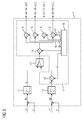
- the regulators 15, 15 ' is according to FIG. 3 downstream of a linearization unit 17.
- the linearization unit 17 has multipliers 18 and a detection device 19.
- the determination means 19 determines in a manner to be explained linearization factors fa to fd and outputs the linearization factors fa to fd to the multipliers 18.
- the multipliers 18 continue to receive from the controller 15 the provisional manipulated variable u, u 'and multiply the provisional manipulated variable u, u' with the linearization factors fa to fd supplied to them.
- the linearization unit 17 determines in this way the final manipulated variables ua to ud, which are output to the valve control units 7a to 7d.
- valve control units 7a to 7d adjust according to the control variables transmitted to them, inter alia, to ud. This causes the piston 3 is displaced or adjusted at an adjustment speed v.
- the determination device 19 of the linearization unit 17 determines the linearization factors fa to fd dynamically as a function of at least the actual position s of the piston 3, the working pressures pA, pB prevailing on both sides of the piston 3 and the working pressures pP, pT prevailing on the pump and tank side of the valve control units 7a to 7d.
- the determination device 19 determines the linearization factors fa to fd such that a ratio of the adjustment speed v for position control to the difference ⁇ s of the setpoint position s * and actual position s and force control to the difference ⁇ F of the setpoint force F * and actual force F is independent of the actual position s and the working pressures pA, pB, pP, pT.
- the control device 11 is usually clocked with a power stroke T. With the frequency of the working clock T takes the control device 11 in each case a new setpoint s *, F * and a new actual size s, F opposite determines the control variables, inter alia, to ud and outputs the control variables, inter alia, to ud to the valve control units 7a to 7d.
- the determination device 19 is in each case supplied with a new value for the actual position s and the working pressures pA, pB prevailing on both sides of the piston 3. Furthermore, the determination device 19 is supplied with the sign of the control difference ⁇ s, ⁇ F. The cyclic feeding of these quantities s, pA, pB, ⁇ s, ⁇ F is in the FIG. 4 and 5 indicated that the detection means 19 is a latch 19 'upstream, which is clocked with the power stroke T.
- the pump pressure pP and the tank pressure pT are usually constant. It is therefore possible to supply these two pressures pP, pT to the determination device 19 once (that is to say in advance and therefore as a parameter). Alternatively, however, it is also possible to clock the pump-side working pressure pP and the tank-side working pressure pT of the determination device 19 and thus to supply it as a variable.
- the determination device 19 requires further data for the exact calculation of the linearization factors fa to fd.
- the further data generally include performance data pN, QNA, QNB of the valve control unit 7, the working surfaces AKA, AKB effective on both sides of the piston 3 as well as the minimum possible effective volumes VminA, VminB on both sides of the piston 3. These values may be fixedly assigned to the determination device 19, for example by the software module 12. Alternatively, the further data may be predetermined to the determination device 19 after the control device 11 has been programmed as a parameter (ie during the startup of the control device 11) be maintained unchanged during operation of the control device 11.
- the linearization factors fa to fd can be according to FIG. 3 as a product of a base linearization factor f and a respective additional linearization factor fa 'to fd'.
- the base linearization factor f is uniform for all linearization factors fa to fd.
- the additional linearization factors fa 'to fd' are individual for the respective linearization factor fa to fd.
- the base linearization factor f is dependent on the sign of the control difference ⁇ s, ⁇ F. In the case of a position control, the base linearization factor f is thus dependent on the direction of movement of the piston 3, that is, on the direction in which the piston 3 is to be displaced. In the following it is assumed that the control difference ⁇ s, ⁇ F is greater than zero.
- the Basislinearmaschines tone f thus corresponds to the (single) linearization factor, which in the DE 10 2007 051 857 B3 and the corresponding US script is determined.
- the determination device 19 takes into account the FIG. 4 and 5 preferably in addition a parameter P which is supplied to the detection device 19 from the outside, for example by an operator.
- the parameter P may be a binary value, may be an analog variable, may be a plurality of binary values, and may even be a plurality of analog variables.
- the determination device 19 sets according to FIG. 4 the additional linearization factors fa 'and fd' to non-zero values, the additional linearization factors fb 'and fc' to the value zero.
- the additional linearization factors fa 'and fd' can in particular have the same value, for example the value 1.
- the determination device 19 sets according to FIG. 4 the additional linearization factors fb ' and fc 'to values other than zero, the additional linearization factors fa' and fd 'to the value zero.
- the additional linearization factors fb 'and fc' may in particular have the same value, for example the value 1.
- the additional linearization factors fb 'and fc' in this case have the value zero.
- the additional linearization factors fa 'and fd' in this case have the value zero.
- E means the elasticity constant of the hydraulic fluid 10.
- the inventive arrangement of hydraulic cylinder unit 1 and control device 11 is in principle arbitrarily applicable. Preferably, however, it is according to FIG. 6 for the employment regulation of an in FIG. 6 schematically indicated rolling stand 20 used.
- the present invention has many advantages.
- an optimal operation of the control device 11 takes place at each operating point of the hydraulic cylinder unit 1.
- the control is completely linearized. Transformations (compare non-linear HGC) are not required.
- a simple integration of the present invention into existing control systems possible because already existing superimposed control structures (meshed controls and the like) need not be changed. This results in a simplified commissioning and maintainability of the control device 11 according to the present invention.
Landscapes
- Engineering & Computer Science (AREA)
- Physics & Mathematics (AREA)
- General Physics & Mathematics (AREA)
- Automation & Control Theory (AREA)
- General Engineering & Computer Science (AREA)
- Fluid Mechanics (AREA)
- Mechanical Engineering (AREA)
- Fluid-Pressure Circuits (AREA)
Claims (9)
- Dispositif de régulation destiné à la régulation d'une unité à vérin hydraulique (1),- dans lequel le dispositif de régulation présente un régulateur (15, 15'), mis en place côté entrée pour recevoir une grandeur théorique (s*, F*) et une grandeur réelle (s, F) et pour établir à l'aide de la différence (δs, δF) entre la grandeur théorique (s*, F*) et la grandeur réelle (s, F) une grandeur de commande préliminaire (u, u') pour des unités de commande de soupapes (7) de l'unité à vérin hydraulique (1),- dans lequel la grandeur théorique (s*, F*) est une position théorique (s*) adoptée par un piston (3) de l'unité à vérin hydraulique (1) et la grandeur réelle (s, F) est une position réelle (s) adoptée par le piston (3) ou la grandeur théorique (s*, F*) est une force théorique (F*) à exercer par le piston (3) et la grandeur réelle (s, F) est une force réelle (F) exercée par le piston (3),- dans lequel une unité de linéarisation (17) est installée en aval du régulateur (15, 15'), mise en place à l'aide de la grandeur de commande préliminaire (u, u') et de facteurs de linéarisation (fa à fd) pour établir des grandeurs de commande définitives (ua à ud) et distribuer les unités de commande de soupapes (7a à 7d), de sorte que le piston (3) est réglé avec une vitesse de réglage (v),- dans lequel l'unité de linéarisation (17) est mise en place pour déterminer les facteurs de linéarisation (fa à fd) de manière dynamique en tant que fonction au moins de la position réelle (s) du piston (3) et des pressions de fonctionnement (pA, pB, pP, pT) régnant des deux côtés du piston (3) ainsi que côté pompe et côté cuve des unités de commande de soupapes (7a à 7d),- dans lequel l'unité de linéarisation (17) est mise en place pour déterminer les facteurs de linéarisation (fa à fd) de telle sorte qu'un rapport de la vitesse de réglage (v) par rapport à la différence (δs, δF) entre la grandeur théorique (s*, F*) et la grandeur réelle (s, F) est indépendant de la position réelle (s) du piston (3) et des pressions de fonctionnement (pA, pB, pP, pT).
- Dispositif de régulation selon la revendication 1,
caractérisé en ce qu'à l'unité de linéarisation (17) est en outre conduit un paramètre (P) et l'unité de linéarisation (17) est mise en place pour prendre en compte le paramètre (P) lors de la détermination des facteurs de linéarisation (fa à fd). - Dispositif de régulation selon la revendication 2,
caractérisé en ce que l'unité de linéarisation (17) est mise en place dans le cas où le paramètre (P) présente une première valeur (P1) pour déterminer les facteurs de linéarisation (fa à fd) de telle sorte que deux des facteurs de linéarisation (fa à fd) présentent la valeur zéro et deux autres des facteurs de linéarisation (f) présentent des valeurs différentes de zéro. - Dispositif de régulation selon la revendication 2 ou 3,
caractérisé en ce que l'unité de linéarisation (17) est mise en place dans le cas où le paramètre (P) présente une deuxième valeur (P2) pour déterminer les facteurs de linéarisation (fa à fd) de telle sorte que la somme des pressions de fonctionnement (pA, pB) régnant des deux côtés du piston (3) se rapproche de la somme des pressions de fonctionnement (pP, pT) régnant côté pompe et côté cuve des unités de commande de soupapes (7a à 7d). - Dispositif de régulation selon l'une des revendications mentionnées ci-dessus,
caractérisé en ce que les unités de commande de soupapes (7a à 7d) sont configurées en tant que soupapes de commande à commande binaire. - Dispositif de régulation selon l'une des revendications mentionnées ci-dessus,
caractérisé en ce qu'il est configuré en tant que dispositif de régulation programmable par logiciel et est programmé avec un module logiciel (12) de sorte qu'il est configuré en raison de la programmation avec le module logiciel (12) selon l'une des revendications mentionnées ci-dessus. - Module logiciel, qui comprend un code machine (14),
caractérisé en ce qu'un dispositif de régulation programmable par logiciel raccordé à une unité à vérin hydraulique (1) est configuré en raison de la programmation avec le module logiciel en tant que dispositif de régulation (11) selon la revendication 6. - Support de données, sur lequel un module logiciel (12) selon la revendication 7 est mis en mémoire sous une forme lisible par une machine.
- Utilisation d'une unité à vérin hydraulique (1) régulée au moyen d'un dispositif de régulation (11) selon l'une des revendications 1 à 6 en vue de la régulation de l'emploi d'une cage de laminoir (20).
Priority Applications (1)
| Application Number | Priority Date | Filing Date | Title |
|---|---|---|---|
| EP13722706.2A EP2836879B1 (fr) | 2012-05-16 | 2013-04-24 | Dispositif de régulation pour une unité de cylindre hydraulique avec commande séparée de chaque soupape |
Applications Claiming Priority (3)
| Application Number | Priority Date | Filing Date | Title |
|---|---|---|---|
| EP12168164.7A EP2664968A1 (fr) | 2012-05-16 | 2012-05-16 | Dispositif de régulation pour une unité de cylindre hydraulique avec commande séparée de chaque soupape |
| PCT/EP2013/058423 WO2013171041A1 (fr) | 2012-05-16 | 2013-04-24 | Système de réglage d'un ensemble vérin hydraulique commandé par une seule vanne |
| EP13722706.2A EP2836879B1 (fr) | 2012-05-16 | 2013-04-24 | Dispositif de régulation pour une unité de cylindre hydraulique avec commande séparée de chaque soupape |
Publications (2)
| Publication Number | Publication Date |
|---|---|
| EP2836879A1 EP2836879A1 (fr) | 2015-02-18 |
| EP2836879B1 true EP2836879B1 (fr) | 2016-11-23 |
Family
ID=48444339
Family Applications (2)
| Application Number | Title | Priority Date | Filing Date |
|---|---|---|---|
| EP12168164.7A Withdrawn EP2664968A1 (fr) | 2012-05-16 | 2012-05-16 | Dispositif de régulation pour une unité de cylindre hydraulique avec commande séparée de chaque soupape |
| EP13722706.2A Not-in-force EP2836879B1 (fr) | 2012-05-16 | 2013-04-24 | Dispositif de régulation pour une unité de cylindre hydraulique avec commande séparée de chaque soupape |
Family Applications Before (1)
| Application Number | Title | Priority Date | Filing Date |
|---|---|---|---|
| EP12168164.7A Withdrawn EP2664968A1 (fr) | 2012-05-16 | 2012-05-16 | Dispositif de régulation pour une unité de cylindre hydraulique avec commande séparée de chaque soupape |
Country Status (5)
| Country | Link |
|---|---|
| US (1) | US9945395B2 (fr) |
| EP (2) | EP2664968A1 (fr) |
| CN (1) | CN104412180B (fr) |
| BR (1) | BR112014028402A2 (fr) |
| WO (1) | WO2013171041A1 (fr) |
Families Citing this family (1)
| Publication number | Priority date | Publication date | Assignee | Title |
|---|---|---|---|---|
| DE102019209091A1 (de) * | 2019-06-24 | 2020-12-24 | Festo Se & Co. Kg | Verfahren zum Betreiben eines Fluidsystems, Fluidsystem und Computerprogrammprodukt |
Family Cites Families (12)
| Publication number | Priority date | Publication date | Assignee | Title |
|---|---|---|---|---|
| US3110152A (en) * | 1961-05-01 | 1963-11-12 | Int Harvester Co | Starting and operating control system for free piston engine hydraulic pump as a power plant of a hydrostatic driven vehicle |
| US4653986A (en) * | 1983-07-28 | 1987-03-31 | Tidewater Compression Service, Inc. | Hydraulically powered compressor and hydraulic control and power system therefor |
| DE3445516C1 (de) * | 1984-12-13 | 1989-05-18 | Mannesmann Rexroth GmbH, 8770 Lohr | Steuervorrichtung fuer eine Regelpumpe |
| US7114432B1 (en) * | 2005-02-09 | 2006-10-03 | Sauer-Danfoss Inc. | Torque limiting device for hydraulic piston pump |
| DE102005042168A1 (de) * | 2005-06-08 | 2006-12-14 | Sms Demag Ag | Vorrichtung zur Beaufschlagung der Führungsflächen von in den Ständerfenstern von Walzgerüsten geführten Lagereinbaustücken |
| AT502348B1 (de) * | 2005-08-17 | 2008-09-15 | Voest Alpine Ind Anlagen | Regelungsverfahren und regler für ein mechanisch- hydraulisches system mit einem mechanischen freiheitsgrad pro hydraulischem aktuator |
| JP4425253B2 (ja) * | 2006-08-30 | 2010-03-03 | ダイキン工業株式会社 | 油圧ユニットおよび油圧ユニットにおけるモータの速度制御方法 |
| DE102007003243A1 (de) | 2007-01-23 | 2008-07-31 | Siemens Ag | Regelanordnung für ein Walzgerüst und hiermit korrespondierende Gegenstände |
| DE102007051857B3 (de) * | 2007-10-30 | 2009-04-23 | Siemens Ag | Regeleinrichtung zum Positionsregeln einer Hydraulikzylindereinheit mit Linearisierungseinheit |
| DE102008003798A1 (de) * | 2008-01-10 | 2009-07-16 | Robert Bosch Gmbh | Verfahren für die Steuerung eines Magnetventils |
| JP2008232445A (ja) * | 2008-06-13 | 2008-10-02 | Daikin Ind Ltd | 油圧ユニットおよび油圧ユニットにおけるモータの速度制御方法 |
| US8591200B2 (en) * | 2009-11-23 | 2013-11-26 | National Oil Well Varco, L.P. | Hydraulically controlled reciprocating pump system |
-
2012
- 2012-05-16 EP EP12168164.7A patent/EP2664968A1/fr not_active Withdrawn
-
2013
- 2013-04-24 WO PCT/EP2013/058423 patent/WO2013171041A1/fr not_active Ceased
- 2013-04-24 BR BR112014028402A patent/BR112014028402A2/pt not_active IP Right Cessation
- 2013-04-24 CN CN201380025612.XA patent/CN104412180B/zh not_active Expired - Fee Related
- 2013-04-24 US US14/401,684 patent/US9945395B2/en not_active Expired - Fee Related
- 2013-04-24 EP EP13722706.2A patent/EP2836879B1/fr not_active Not-in-force
Non-Patent Citations (1)
| Title |
|---|
| None * |
Also Published As
| Publication number | Publication date |
|---|---|
| WO2013171041A1 (fr) | 2013-11-21 |
| CN104412180B (zh) | 2017-01-18 |
| EP2664968A1 (fr) | 2013-11-20 |
| CN104412180A (zh) | 2015-03-11 |
| BR112014028402A2 (pt) | 2018-04-24 |
| US20150142183A1 (en) | 2015-05-21 |
| EP2836879A1 (fr) | 2015-02-18 |
| US9945395B2 (en) | 2018-04-17 |
Similar Documents
| Publication | Publication Date | Title |
|---|---|---|
| EP2206031B1 (fr) | Dispositif de régulation servant à la régulation de position d'un ensemble vérin hydraulique et comprenant une unité de linéarisation | |
| DE19839062C2 (de) | Hydraulische Maschinensteuerung | |
| DE102017213650A1 (de) | Verfahren zum Regeln eines hydraulischen Systems, Regeleinheit für ein hydraulisches System und hydraulisches System | |
| EP2664804A2 (fr) | Régulateur de pression et de débit, unité de réglage pour une machine de refoulement hydraulique réglable dotée d'un régulateur de pression et de débit et procédé de régulation d'une telle unité de réglage | |
| EP3816455A1 (fr) | Dispositif de commande hydraulique destiné à l'alimentation en fluide de pression d'au moins deux consommateurs hydrauliques | |
| EP2125258B1 (fr) | Dispositif de réglage pour une cage de laminoir et objets correspondants à cet effet | |
| WO2018210448A2 (fr) | Procédé de fonctionnement d'une presse à poudre à régulation de position et presse à poudre pour mettre en œuvre le procédé | |
| EP3988801A1 (fr) | Procédé de fonctionnement d'un entraînement hydraulique | |
| EP1915650B1 (fr) | Procede de regulation et regulateur destines a un systeme mecanique/hydraulique | |
| EP3953771A1 (fr) | Unité de travail hydrostatique et procédé pour sa commande | |
| DE102023210960B3 (de) | Verfahren zum Betrieb einer Axialkolbenmaschine bei dem ein Nullfall berücksichtigt ist | |
| EP0515639A1 (fr) | Systeme hydraulique. | |
| DE102016214708A1 (de) | Stetigventileinheit, hydraulische Achse und Verfahren zum Betreiben einer hydraulischen Achse | |
| EP4081871B1 (fr) | Procédé de commande d'un système partiellement électronique | |
| DE102022206535A1 (de) | Verfahren zur Regelung von hydraulischen Komponenten | |
| EP2664968A1 (fr) | Dispositif de régulation pour une unité de cylindre hydraulique avec commande séparée de chaque soupape | |
| EP2853752B1 (fr) | Système de régulation | |
| EP4118334B1 (fr) | Dispositif de régulation d'une pompe hydraulique ou d'un moteur hydraulique | |
| EP3230813B1 (fr) | Procédé d'identification d'une courbe caractéristique | |
| EP3134774B1 (fr) | Dispositif de réglage de vérin hydraulique à linéarisation optimisée | |
| DE102022208574A1 (de) | Verfahren zum Betreiben eines hydraulischen Antriebs einer Maschine und hydraulischer Antrieb | |
| EP3895819B1 (fr) | Fonctionnement d'un dispositif de refrodissement avec une pression de fonctionnement minimale | |
| EP3708297A1 (fr) | Commande optimisée d'un amortisseur de vibrations actif | |
| WO2010136271A2 (fr) | Procédé de commande d'un régulateur hydraulique numérique | |
| DE102023203387A1 (de) | Verfahren zum Betreiben eines hydraulischen Antriebsystems |
Legal Events
| Date | Code | Title | Description |
|---|---|---|---|
| PUAI | Public reference made under article 153(3) epc to a published international application that has entered the european phase |
Free format text: ORIGINAL CODE: 0009012 |
|
| 17P | Request for examination filed |
Effective date: 20141110 |
|
| AK | Designated contracting states |
Kind code of ref document: A1 Designated state(s): AL AT BE BG CH CY CZ DE DK EE ES FI FR GB GR HR HU IE IS IT LI LT LU LV MC MK MT NL NO PL PT RO RS SE SI SK SM TR |
|
| AX | Request for extension of the european patent |
Extension state: BA ME |
|
| RAP1 | Party data changed (applicant data changed or rights of an application transferred) |
Owner name: PRIMETALS TECHNOLOGIES GERMANY GMBH |
|
| DAX | Request for extension of the european patent (deleted) | ||
| GRAP | Despatch of communication of intention to grant a patent |
Free format text: ORIGINAL CODE: EPIDOSNIGR1 |
|
| INTG | Intention to grant announced |
Effective date: 20160802 |
|
| GRAS | Grant fee paid |
Free format text: ORIGINAL CODE: EPIDOSNIGR3 |
|
| GRAA | (expected) grant |
Free format text: ORIGINAL CODE: 0009210 |
|
| AK | Designated contracting states |
Kind code of ref document: B1 Designated state(s): AL AT BE BG CH CY CZ DE DK EE ES FI FR GB GR HR HU IE IS IT LI LT LU LV MC MK MT NL NO PL PT RO RS SE SI SK SM TR |
|
| REG | Reference to a national code |
Ref country code: GB Ref legal event code: FG4D Free format text: NOT ENGLISH |
|
| REG | Reference to a national code |
Ref country code: CH Ref legal event code: EP |
|
| REG | Reference to a national code |
Ref country code: IE Ref legal event code: FG4D Free format text: LANGUAGE OF EP DOCUMENT: GERMAN |
|
| REG | Reference to a national code |
Ref country code: AT Ref legal event code: REF Ref document number: 848458 Country of ref document: AT Kind code of ref document: T Effective date: 20161215 |
|
| REG | Reference to a national code |
Ref country code: DE Ref legal event code: R096 Ref document number: 502013005484 Country of ref document: DE |
|
| PG25 | Lapsed in a contracting state [announced via postgrant information from national office to epo] |
Ref country code: LV Free format text: LAPSE BECAUSE OF FAILURE TO SUBMIT A TRANSLATION OF THE DESCRIPTION OR TO PAY THE FEE WITHIN THE PRESCRIBED TIME-LIMIT Effective date: 20161123 |
|
| REG | Reference to a national code |
Ref country code: SE Ref legal event code: TRGR |
|
| REG | Reference to a national code |
Ref country code: LT Ref legal event code: MG4D |
|
| REG | Reference to a national code |
Ref country code: NL Ref legal event code: MP Effective date: 20161123 |
|
| REG | Reference to a national code |
Ref country code: FR Ref legal event code: PLFP Year of fee payment: 5 |
|
| PG25 | Lapsed in a contracting state [announced via postgrant information from national office to epo] |
Ref country code: GR Free format text: LAPSE BECAUSE OF FAILURE TO SUBMIT A TRANSLATION OF THE DESCRIPTION OR TO PAY THE FEE WITHIN THE PRESCRIBED TIME-LIMIT Effective date: 20170224 Ref country code: NL Free format text: LAPSE BECAUSE OF FAILURE TO SUBMIT A TRANSLATION OF THE DESCRIPTION OR TO PAY THE FEE WITHIN THE PRESCRIBED TIME-LIMIT Effective date: 20161123 Ref country code: NO Free format text: LAPSE BECAUSE OF FAILURE TO SUBMIT A TRANSLATION OF THE DESCRIPTION OR TO PAY THE FEE WITHIN THE PRESCRIBED TIME-LIMIT Effective date: 20170223 Ref country code: LT Free format text: LAPSE BECAUSE OF FAILURE TO SUBMIT A TRANSLATION OF THE DESCRIPTION OR TO PAY THE FEE WITHIN THE PRESCRIBED TIME-LIMIT Effective date: 20161123 |
|
| PG25 | Lapsed in a contracting state [announced via postgrant information from national office to epo] |
Ref country code: PL Free format text: LAPSE BECAUSE OF FAILURE TO SUBMIT A TRANSLATION OF THE DESCRIPTION OR TO PAY THE FEE WITHIN THE PRESCRIBED TIME-LIMIT Effective date: 20161123 Ref country code: PT Free format text: LAPSE BECAUSE OF FAILURE TO SUBMIT A TRANSLATION OF THE DESCRIPTION OR TO PAY THE FEE WITHIN THE PRESCRIBED TIME-LIMIT Effective date: 20170323 Ref country code: FI Free format text: LAPSE BECAUSE OF FAILURE TO SUBMIT A TRANSLATION OF THE DESCRIPTION OR TO PAY THE FEE WITHIN THE PRESCRIBED TIME-LIMIT Effective date: 20161123 Ref country code: HR Free format text: LAPSE BECAUSE OF FAILURE TO SUBMIT A TRANSLATION OF THE DESCRIPTION OR TO PAY THE FEE WITHIN THE PRESCRIBED TIME-LIMIT Effective date: 20161123 Ref country code: ES Free format text: LAPSE BECAUSE OF FAILURE TO SUBMIT A TRANSLATION OF THE DESCRIPTION OR TO PAY THE FEE WITHIN THE PRESCRIBED TIME-LIMIT Effective date: 20161123 Ref country code: RS Free format text: LAPSE BECAUSE OF FAILURE TO SUBMIT A TRANSLATION OF THE DESCRIPTION OR TO PAY THE FEE WITHIN THE PRESCRIBED TIME-LIMIT Effective date: 20161123 |
|
| PG25 | Lapsed in a contracting state [announced via postgrant information from national office to epo] |
Ref country code: DK Free format text: LAPSE BECAUSE OF FAILURE TO SUBMIT A TRANSLATION OF THE DESCRIPTION OR TO PAY THE FEE WITHIN THE PRESCRIBED TIME-LIMIT Effective date: 20161123 Ref country code: RO Free format text: LAPSE BECAUSE OF FAILURE TO SUBMIT A TRANSLATION OF THE DESCRIPTION OR TO PAY THE FEE WITHIN THE PRESCRIBED TIME-LIMIT Effective date: 20161123 Ref country code: SK Free format text: LAPSE BECAUSE OF FAILURE TO SUBMIT A TRANSLATION OF THE DESCRIPTION OR TO PAY THE FEE WITHIN THE PRESCRIBED TIME-LIMIT Effective date: 20161123 Ref country code: EE Free format text: LAPSE BECAUSE OF FAILURE TO SUBMIT A TRANSLATION OF THE DESCRIPTION OR TO PAY THE FEE WITHIN THE PRESCRIBED TIME-LIMIT Effective date: 20161123 Ref country code: CZ Free format text: LAPSE BECAUSE OF FAILURE TO SUBMIT A TRANSLATION OF THE DESCRIPTION OR TO PAY THE FEE WITHIN THE PRESCRIBED TIME-LIMIT Effective date: 20161123 |
|
| REG | Reference to a national code |
Ref country code: DE Ref legal event code: R097 Ref document number: 502013005484 Country of ref document: DE |
|
| PG25 | Lapsed in a contracting state [announced via postgrant information from national office to epo] |
Ref country code: BG Free format text: LAPSE BECAUSE OF FAILURE TO SUBMIT A TRANSLATION OF THE DESCRIPTION OR TO PAY THE FEE WITHIN THE PRESCRIBED TIME-LIMIT Effective date: 20170223 Ref country code: SM Free format text: LAPSE BECAUSE OF FAILURE TO SUBMIT A TRANSLATION OF THE DESCRIPTION OR TO PAY THE FEE WITHIN THE PRESCRIBED TIME-LIMIT Effective date: 20161123 |
|
| PLBE | No opposition filed within time limit |
Free format text: ORIGINAL CODE: 0009261 |
|
| STAA | Information on the status of an ep patent application or granted ep patent |
Free format text: STATUS: NO OPPOSITION FILED WITHIN TIME LIMIT |
|
| 26N | No opposition filed |
Effective date: 20170824 |
|
| PG25 | Lapsed in a contracting state [announced via postgrant information from national office to epo] |
Ref country code: SI Free format text: LAPSE BECAUSE OF FAILURE TO SUBMIT A TRANSLATION OF THE DESCRIPTION OR TO PAY THE FEE WITHIN THE PRESCRIBED TIME-LIMIT Effective date: 20161123 |
|
| REG | Reference to a national code |
Ref country code: CH Ref legal event code: PL |
|
| GBPC | Gb: european patent ceased through non-payment of renewal fee |
Effective date: 20170424 |
|
| REG | Reference to a national code |
Ref country code: IE Ref legal event code: MM4A |
|
| PG25 | Lapsed in a contracting state [announced via postgrant information from national office to epo] |
Ref country code: MC Free format text: LAPSE BECAUSE OF FAILURE TO SUBMIT A TRANSLATION OF THE DESCRIPTION OR TO PAY THE FEE WITHIN THE PRESCRIBED TIME-LIMIT Effective date: 20161123 |
|
| PG25 | Lapsed in a contracting state [announced via postgrant information from national office to epo] |
Ref country code: LI Free format text: LAPSE BECAUSE OF NON-PAYMENT OF DUE FEES Effective date: 20170430 Ref country code: CH Free format text: LAPSE BECAUSE OF NON-PAYMENT OF DUE FEES Effective date: 20170430 Ref country code: LU Free format text: LAPSE BECAUSE OF NON-PAYMENT OF DUE FEES Effective date: 20170424 Ref country code: GB Free format text: LAPSE BECAUSE OF NON-PAYMENT OF DUE FEES Effective date: 20170424 |
|
| REG | Reference to a national code |
Ref country code: BE Ref legal event code: MM Effective date: 20170430 |
|
| REG | Reference to a national code |
Ref country code: FR Ref legal event code: PLFP Year of fee payment: 6 |
|
| PG25 | Lapsed in a contracting state [announced via postgrant information from national office to epo] |
Ref country code: IE Free format text: LAPSE BECAUSE OF NON-PAYMENT OF DUE FEES Effective date: 20170424 |
|
| PG25 | Lapsed in a contracting state [announced via postgrant information from national office to epo] |
Ref country code: BE Free format text: LAPSE BECAUSE OF NON-PAYMENT OF DUE FEES Effective date: 20170430 |
|
| PG25 | Lapsed in a contracting state [announced via postgrant information from national office to epo] |
Ref country code: MT Free format text: LAPSE BECAUSE OF FAILURE TO SUBMIT A TRANSLATION OF THE DESCRIPTION OR TO PAY THE FEE WITHIN THE PRESCRIBED TIME-LIMIT Effective date: 20161123 |
|
| REG | Reference to a national code |
Ref country code: AT Ref legal event code: MM01 Ref document number: 848458 Country of ref document: AT Kind code of ref document: T Effective date: 20180424 |
|
| PG25 | Lapsed in a contracting state [announced via postgrant information from national office to epo] |
Ref country code: HU Free format text: LAPSE BECAUSE OF FAILURE TO SUBMIT A TRANSLATION OF THE DESCRIPTION OR TO PAY THE FEE WITHIN THE PRESCRIBED TIME-LIMIT; INVALID AB INITIO Effective date: 20130424 |
|
| PGFP | Annual fee paid to national office [announced via postgrant information from national office to epo] |
Ref country code: FI Payment date: 20190409 Year of fee payment: 8 |
|
| PG25 | Lapsed in a contracting state [announced via postgrant information from national office to epo] |
Ref country code: CY Free format text: LAPSE BECAUSE OF FAILURE TO SUBMIT A TRANSLATION OF THE DESCRIPTION OR TO PAY THE FEE WITHIN THE PRESCRIBED TIME-LIMIT Effective date: 20161123 Ref country code: AT Free format text: LAPSE BECAUSE OF NON-PAYMENT OF DUE FEES Effective date: 20180424 |
|
| PG25 | Lapsed in a contracting state [announced via postgrant information from national office to epo] |
Ref country code: MK Free format text: LAPSE BECAUSE OF FAILURE TO SUBMIT A TRANSLATION OF THE DESCRIPTION OR TO PAY THE FEE WITHIN THE PRESCRIBED TIME-LIMIT Effective date: 20161123 |
|
| PG25 | Lapsed in a contracting state [announced via postgrant information from national office to epo] |
Ref country code: TR Free format text: LAPSE BECAUSE OF FAILURE TO SUBMIT A TRANSLATION OF THE DESCRIPTION OR TO PAY THE FEE WITHIN THE PRESCRIBED TIME-LIMIT Effective date: 20161123 |
|
| REG | Reference to a national code |
Ref country code: DE Ref legal event code: R081 Ref document number: 502013005484 Country of ref document: DE Owner name: PRIMETALS TECHNOLOGIES GERMANY GMBH, DE Free format text: FORMER OWNER: PRIMETALS TECHNOLOGIES GERMANY GMBH, 91052 ERLANGEN, DE |
|
| PG25 | Lapsed in a contracting state [announced via postgrant information from national office to epo] |
Ref country code: AL Free format text: LAPSE BECAUSE OF FAILURE TO SUBMIT A TRANSLATION OF THE DESCRIPTION OR TO PAY THE FEE WITHIN THE PRESCRIBED TIME-LIMIT Effective date: 20161123 Ref country code: IS Free format text: LAPSE BECAUSE OF FAILURE TO SUBMIT A TRANSLATION OF THE DESCRIPTION OR TO PAY THE FEE WITHIN THE PRESCRIBED TIME-LIMIT Effective date: 20170323 |
|
| PGFP | Annual fee paid to national office [announced via postgrant information from national office to epo] |
Ref country code: DE Payment date: 20200420 Year of fee payment: 8 Ref country code: FR Payment date: 20200420 Year of fee payment: 8 |
|
| PGFP | Annual fee paid to national office [announced via postgrant information from national office to epo] |
Ref country code: IT Payment date: 20200428 Year of fee payment: 8 |
|
| PG25 | Lapsed in a contracting state [announced via postgrant information from national office to epo] |
Ref country code: SE Free format text: LAPSE BECAUSE OF NON-PAYMENT OF DUE FEES Effective date: 20200425 |
|
| REG | Reference to a national code |
Ref country code: DE Ref legal event code: R119 Ref document number: 502013005484 Country of ref document: DE |
|
| PG25 | Lapsed in a contracting state [announced via postgrant information from national office to epo] |
Ref country code: DE Free format text: LAPSE BECAUSE OF NON-PAYMENT OF DUE FEES Effective date: 20211103 Ref country code: FR Free format text: LAPSE BECAUSE OF NON-PAYMENT OF DUE FEES Effective date: 20210430 |
|
| PG25 | Lapsed in a contracting state [announced via postgrant information from national office to epo] |
Ref country code: IT Free format text: LAPSE BECAUSE OF NON-PAYMENT OF DUE FEES Effective date: 20200424 |
|
| PG25 | Lapsed in a contracting state [announced via postgrant information from national office to epo] |
Ref country code: IT Free format text: LAPSE BECAUSE OF NON-PAYMENT OF DUE FEES Effective date: 20210424 |