EP2837079B1 - Compensateur de puissance - Google Patents
Compensateur de puissance Download PDFInfo
- Publication number
- EP2837079B1 EP2837079B1 EP13715963.8A EP13715963A EP2837079B1 EP 2837079 B1 EP2837079 B1 EP 2837079B1 EP 13715963 A EP13715963 A EP 13715963A EP 2837079 B1 EP2837079 B1 EP 2837079B1
- Authority
- EP
- European Patent Office
- Prior art keywords
- voltage
- power
- vsx
- compensator
- controller
- Prior art date
- Legal status (The legal status is an assumption and is not a legal conclusion. Google has not performed a legal analysis and makes no representation as to the accuracy of the status listed.)
- Active
Links
Images




Classifications
-
- H—ELECTRICITY
- H02—GENERATION; CONVERSION OR DISTRIBUTION OF ELECTRIC POWER
- H02J—ELECTRIC POWER NETWORKS; CIRCUIT ARRANGEMENTS OR SYSTEMS FOR SUPPLYING OR DISTRIBUTING ELECTRIC POWER; SYSTEMS FOR STORING ELECTRIC ENERGY
- H02J3/00—Circuit arrangements for AC mains or AC distribution networks
- H02J3/18—Arrangements for adjusting, eliminating or compensating reactive power in networks
-
- H—ELECTRICITY
- H02—GENERATION; CONVERSION OR DISTRIBUTION OF ELECTRIC POWER
- H02J—ELECTRIC POWER NETWORKS; CIRCUIT ARRANGEMENTS OR SYSTEMS FOR SUPPLYING OR DISTRIBUTING ELECTRIC POWER; SYSTEMS FOR STORING ELECTRIC ENERGY
- H02J3/00—Circuit arrangements for AC mains or AC distribution networks
- H02J3/001—Arrangements for handling faults or abnormalities, e.g. emergencies or contingencies
- H02J3/0014—Arrangements for handling faults or abnormalities, e.g. emergencies or contingencies for preventing or reducing power oscillations in networks
-
- H—ELECTRICITY
- H02—GENERATION; CONVERSION OR DISTRIBUTION OF ELECTRIC POWER
- H02J—ELECTRIC POWER NETWORKS; CIRCUIT ARRANGEMENTS OR SYSTEMS FOR SUPPLYING OR DISTRIBUTING ELECTRIC POWER; SYSTEMS FOR STORING ELECTRIC ENERGY
- H02J3/00—Circuit arrangements for AC mains or AC distribution networks
- H02J3/18—Arrangements for adjusting, eliminating or compensating reactive power in networks
- H02J3/1807—Arrangements for adjusting, eliminating or compensating reactive power in networks using series compensators, e.g. thyristor-controlled series capacitors [TCSC]
- H02J3/1814—Arrangements for adjusting, eliminating or compensating reactive power in networks using series compensators, e.g. thyristor-controlled series capacitors [TCSC] having reactive elements actively controlled by bridge converters, e.g. unified power flow controllers [UPFC] or controlled series voltage compensators
-
- H—ELECTRICITY
- H02—GENERATION; CONVERSION OR DISTRIBUTION OF ELECTRIC POWER
- H02J—ELECTRIC POWER NETWORKS; CIRCUIT ARRANGEMENTS OR SYSTEMS FOR SUPPLYING OR DISTRIBUTING ELECTRIC POWER; SYSTEMS FOR STORING ELECTRIC ENERGY
- H02J3/00—Circuit arrangements for AC mains or AC distribution networks
- H02J3/001—Arrangements for handling faults or abnormalities, e.g. emergencies or contingencies
- H02J3/0014—Arrangements for handling faults or abnormalities, e.g. emergencies or contingencies for preventing or reducing power oscillations in networks
- H02J3/00142—Oscillations concerning frequency
-
- Y—GENERAL TAGGING OF NEW TECHNOLOGICAL DEVELOPMENTS; GENERAL TAGGING OF CROSS-SECTIONAL TECHNOLOGIES SPANNING OVER SEVERAL SECTIONS OF THE IPC; TECHNICAL SUBJECTS COVERED BY FORMER USPC CROSS-REFERENCE ART COLLECTIONS [XRACs] AND DIGESTS
- Y02—TECHNOLOGIES OR APPLICATIONS FOR MITIGATION OR ADAPTATION AGAINST CLIMATE CHANGE
- Y02E—REDUCTION OF GREENHOUSE GAS [GHG] EMISSIONS, RELATED TO ENERGY GENERATION, TRANSMISSION OR DISTRIBUTION
- Y02E40/00—Technologies for an efficient electrical power generation, transmission or distribution
- Y02E40/10—Flexible AC transmission systems [FACTS]
-
- Y—GENERAL TAGGING OF NEW TECHNOLOGICAL DEVELOPMENTS; GENERAL TAGGING OF CROSS-SECTIONAL TECHNOLOGIES SPANNING OVER SEVERAL SECTIONS OF THE IPC; TECHNICAL SUBJECTS COVERED BY FORMER USPC CROSS-REFERENCE ART COLLECTIONS [XRACs] AND DIGESTS
- Y02—TECHNOLOGIES OR APPLICATIONS FOR MITIGATION OR ADAPTATION AGAINST CLIMATE CHANGE
- Y02E—REDUCTION OF GREENHOUSE GAS [GHG] EMISSIONS, RELATED TO ENERGY GENERATION, TRANSMISSION OR DISTRIBUTION
- Y02E40/00—Technologies for an efficient electrical power generation, transmission or distribution
- Y02E40/30—Reactive power compensation
Definitions
- the present invention relates to a power compensator.
- the power flow is controlled by the power generation plants and the rate of power generation follows the load demand of the cities.
- more and more renewable energy sources will be installed in a distributed manner all over the cities (and thus all over the power grids). Since it is difficult to determine the total rate of power generation of renewable power sources such as wind and solar energy systems, the increasing use of intermittent renewable energy sources is expected to introduce dynamic instability to the ac power supply or commonly called ac mains.
- the control paradigm has to be changed so that, instead of having the power generation following the load demand as in the case of traditional power systems, the load demand should follow the power generation.
- Fig.1a illustrates the basic principle of using a reactive power controller (100) as a series reactive power compensator (controller).
- a reactive power controller 100
- the output voltage V 2 is smaller than the input voltage V 1 .
- Series reactive power controller can be inserted in the output of the transmission line.
- V comp By generating a compensating voltage V comp , the new output V 2 ' can be increased to compensate the voltage drop of the power transmission along the transmission lines.
- the voltage vector of the compensating voltage generated by the reactive power controller is perpendicular to the current of the power flow, as indicated in the vector diagram of Fig.1b in which Vector of V comp is perpendicular to the resistive voltage drop IR (which has the same direction of the current vector I).
- the use of reactive power controller or compensator to boost the output voltage is a prior art. It should however be noted that, in such prior art, it is the output voltage of the reactive power controller (i.e. the output voltage V2') is regulated.
- Reactive power controllers will be known to the skilled reader and are power electronics circuits that contain electronic switches and energy storage elements (such as inductors and/or capacitors). They can be used to utilize the storage energy to control the current and voltage in power systems.
- examples of the usage of reactive power controllers 200 include series reactive power compensator 202, shunt (parallel) reactive power compensator 204 and the unified power flow controller (which uses the combination of series and shunt reactive power controllers).
- isolation transformers are usually used to provide electrical isolation between the high-voltage transmission lines and the electronic circuits of the reactive power controllers as shown in Fig.2 .
- isolation transformers are not compulsory.
- series reactive power controller 300 proposed in patents [ GB2405540.B and US patent US2007057640 ] has been used as a central dimming system for lighting system 306 fed by mains voltage without using isolation transformer.
- Such use of reactive power controller 302 once again regulates the output voltage of the series reactive controller using a standard "output voltage feedback control”.
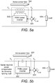
- the power line voltage Vs comprises the control variable to a controller 402 providing an input to a pulse width modulated (PWM) generator 406 in conjunction with a synchronization network input 408 to a pulse width modulator inverter 410 such that the voltage V0 fluctuates allowing power in the non-critical load 412 to vary such that the voltage Vs can be maintained constant.
- PWM pulse width modulated
- the reactive power controller with input voltage control can provide voltage support for the ac mains, it is called “voltage spring” or "electric spring”.
- the reactive power compensation is used as an "electric spring" regulated by Vs
- the active power flow 510 is shown as dissipating across non-critical load 512, the reactive controller 514 being controlled by controller 516 to regulate Vs and maintain the desired voltage across a critical load 518.
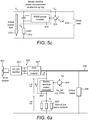
- P in in the input power from the power supply 600 such as a wind turbine V s is the AC mains voltage regulated by controller 608, V o is the voltage across the non-critical load R 1 602, V a is the voltage generated across the reactive power controller 604 (i.e. electric spring).
- R 2 is the critical load 606 that needs a stable V S .
- P R1 and P R2 are the power consumed by R, and R 2 , respectively.
- P in the power generated by a power system with substantial renewable energy sources is not constant. It may vary according to the availability of the renewable power generated with time as shown in Fig. 6b .
- the root-mean-square value of V S can be kept constant. Therefore, if V s is constant in equation (1), P R2 is constant. P R1 will vary to follow the profile of P in because the "input voltage control of V s " will allow V a to fluctuate so that P R1 becomes variable.
- the invention is related to the control methods of reactive power controllers for stabilizing ac power supply. It provides a methodology for allowing reactive power controllers to work in different locations of the transmission lines of an ac power supply and for these reactive power controllers to support and stabilize the ac mains voltage levels at their respective locations of the transmission lines.
- the control scheme in the proposal allows these reactive power controllers to have automatically adjustable voltage references according to the mains voltage levels at the locations of the transmission lines.
- the control method can be applied, but not limited to, reactive power controllers embedded in smart electric loads distributed in the power grid for stabilizing and supporting the ac power supply along the transmission lines. It is a method that is useful for example for stabilizing power grids with substantial penetration of renewable power sources or weakly regulated ac power grids.
- Fig.7 shows an example of having electric loads 1300a. 1300b, 1300c connected along a transmission line. Due to the gradual voltage drop along the transmission line (i.e. voltage drops across the impedance and resistance of the transmission lines), the mains voltage levels along the lines are not identical. Generally, the mains voltage is highest at the power supply source 1302 and decreases gradually towards the end of the transmission line. The mains voltage at different locations (i.e.
- Vs1, Vs2,.., Vsn etc) are not truly identical.
- the mains voltage nearest the transformer may be 230V (which is the nominal voltage) and that farthest from the transformer may be 210V, because of the voltage drop along the long electric cables along the streets. That is, it is natural that Vs1 > Vs2> ...>Vsn.
- Figs.8a and 8b show the circuits of a PWM full-bridge power inverter ( Fig. 8b ) and half-bridge power inverter ( Fig. 8a ) that can be used as the main power circuit.
- Diodes 1402, 1404 behave like a diode rectifier through which a dc capacitor (1406, 1408) can be charged to provide the DC voltage source for the power inverter. Referring to Figs.
- a high-quality PWM voltage waveform (1500, 1502, 1504) at the mains frequency can be generated.
- the low-pass filter (141Q, 1412) comprising an inductor and a capacitor
- a sinusoidal voltage ( V a ) (1500, 1502, 1504) with controllable magnitude according to the control of the modulation index (M) at the mains frequency can be generated as the output of the LC filter, which is also the voltage provided by reactive power controller (or electric spring).
- the phase relationship V a with respect to V s can be controlled.
- the vector of the current through the controller and the vector of the voltage across the controller should be ideally perpendicular to each other.
- a "droop control" concept approach or its equivalent can be employed.
- a droop control of the type used in power systems where several generators are used for power generation [ B.W. Weedy & B.J. Cory, "Electric Power Systems", 4th Edition, New York, Wiley, 1998 ] or for the control of parallel power inverters [ Karel De Brabandere et al, "A voltage and frequency droop control method for parallel inverters", IEEE Transactions on Power Electronics, Vol.22, No.4, July 2007, pp.1107-1115 ] can be adopted.
- Voltage and frequency droop control methods enable the generators to work in parallel in order to be synchronized in frequency and achieve stable operation.
- Vs* can be set for individual controllers.
- a power source 600 such as a wind turbine 601 is rectified at AC-DC rectifier 603 and supplies power line 605 via grid connected inverter 607.
- Voltage Vs across series reactive power controller 604 and load 602 allows variation of Vs across controller 604 in conjunction with Vs across load 602 to provide a desired voltage across critical load 606, by maintaining Vs at Vs-ref at controller 608.
- the aim of the controller in the application example of Fig. 6 is to restore v s to the nominal value of the mains voltage v s_ref'
- p u' be the sum of dynamically-changing wind power and a certain base power generated by an AC power source such as an AC generator.
- Z 1 is the impedance of the "non-critical" load and Z 2 is the impedance of the "critical" load.
- equation (3) shows that, if the mains voltage is regulated by the controller at the nominal value v s_ref' the second power term P 2 should remain constant for the critical load. If the power generated Pin cannot meet the full power for both P 1 and P 2 , the input-voltage control of the controller will generate a voltage vector v a to keep v s regulated at v s_ref' . From (3), the voltage vector v 0 across Z 1 will be reduced and so the power consumption ( P 1 ) of Z 1 will also be reduced. Therefore, if the controller performs well, P 2 for the critical load should remain constant as expected and P 1 for the non-critical load should follow the power generation profile.
- Figs.10a-10d shows the vector diagrams of the system ( Fig. 6 ) with the controller under four operating modes.
- the circle in the vector diagram represents the nominal value of the mains voltage v s_ref (e.g. 220V).
- the vectors are assumed to rotate in an anticlockwise direction at the mains frequency (e.g. 50Hz).
- v s_ref the power generated by the renewable power source (600) (such as a wind farm) is sufficient to meet the load demand and simultaneously maintain v s at the nominal value of v s_ref'
- Fig.10b represents the situation when power reduction in Z 1 is needed in order to keep v s at v s_ref'
- v a is positive in order to provide the "voltage boosting" function under the capacitive mode of the electric spring. If the generated power is higher than the load demand, v s will exceed v s_ref , resulting in an over-voltage situation.
- Fig.10c shows that the controller can provide "voltage reduction" function by operating under the inductive mode.
- v 0 is increased, with respect to its value in Fig.10b , in order that the load Z 1 can consume more power generated by the renewable energy source to keep the power balance.
- the controller operates in a lossless manner and does not consume energy.
- the voltage across Z 1 i.e. v 0
- the controller cannot maintain v s at v s_ref under the capacitive ( Fig.10b ) and inductive ( Fig.10c ) modes.
- the electric spring voltage vector v a which has to be perpendicular with v R1 (or in parallel with vector v L1 ) for reactive power operation, cannot touch the circle and thus reduce v s to v s_ref .
- the controller (1604) has to absorb real power and transfer it to somewhere else such as an energy storage element (not shown) which can be any appropriate element such as a battery through another path.
- an energy storage element not shown
- the vector v a is no longer perpendicular to v R1 . Therefore, the controller on its own without active power absorption means is more effective in voltage boosting than voltage reduction.
- the capacitive mode provides voltage support while inductive mode provides voltage suppression for the ac power system.
- Fig.11 in which the x-axis refers to the modulation (1800) of the PWM voltage, which is effectively an indication of the magnitude of the filtered sinusoidal voltage waveform generated by the controller.
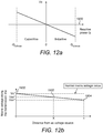
- the capacitive and inductive modes can be represented as a reference to the reactive power Q provided by the controller as shown in Fig.12a .
- the controller provides negative reactive power, it provides voltage support (i.e. positive Va).
- positive Q When it provides positive Q, it generates negative Va.
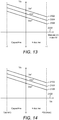
- the exact mains voltage reference values that these controllers need to maintain as their respective reference values are location-dependent and therefore not identical.
- the reference mains voltage for the controller installed immediately next to the ac voltage source is Vs* 1900.
- the mains voltage reference may drop to Vsx* 1902.
- the end of the transmission line i.e.
- control scheme that can be implemented the control board of each controller is proposed.
- the basic concept is illustrated by the schematic of control block as shown in Fig.16 as an example. It should however be stressed that other control blocks with the same control objectives can also be used.
- the control scheme can be implemented in analogue or digital form, or a combination of both.
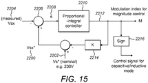
- the controller is assumed to be installed at a distance x from the ac voltage source which has a "nominal" mains voltage Vs* (2202) (e.g. 230V or 110V).
- Vs* mains voltage
- This electric spring is connected to the mains voltage at which the actual (measured) mains voltage is Vsx (2204).
- the control scheme generates an adjustable reference voltage Vsx* (2200), which suits the actual mains voltage at location-x of the transmission or distribution lines.
- the measured Vsx (2204) is subtracted from the Vsx* (2200) at subtractor (2206) and the difference or error signal e (2208) is fed to a proportional-integral (PI) controller (2210).
- the output of the PI control is the modulation index ( M ) (2212).
- M is fed to a gain (2214) K and the signal M K is subtracted at the subtractor (2206) from the nominal mains voltage (2202) Vs* to form the generated adjustable mains voltage reference Vsx*.
- the polarity of M provides a control signal (2216) for the capacitive mode or inductive mode of operation.
- Equation (5) indicates that the adjustable mains voltage reference Vsx* depends on the droop characteristic which is represented by the constant gain K. Since M is a variable, the - M K term on the right-hand side allows this reference voltage to be adjusted according to the voltage drop along the transmission lines.
- equation (6) shows that the operation of the control scheme is to force the measured Vsx to approach the automatically adjustable reference Vsx*.
- M k P e + k I ⁇ e dt
- k P is the proportional coefficient
- k I is the integral coefficient of the PI controller
- the controller of Fig. 15 is provided as controller 2201.
- the control scheme allows control of the voltage across the reactive controller to compensate for droop in the voltage at the location of the controller. Hence instead of tracking the voltage at the origin of the power transmission line the corrected reference voltage of the relevant location is correct. Selection of the gain value K allows the droop characteristic to be incorporated.
- the gain value of K can be preset per device, set at installation or can be remotely set for example via wired or wireless means across a distributed network. Control schemes and approaches to setting the reference voltage value can be adopted as appropriate.
- the proposed control scheme provides additional benefits.
- the most upstream controller provides maximum positive reactive power (i.e. maximum and positive Qa1), meaning that it is operating in its inductive mode to "suppress" its mains voltage at a nominal level Vs1.
- the most downstream controller operates mainly in the capacitive mode by generating primarily negative reactive power (i.e. maximum negative reactive power Qa3) to support the mains voltage Vs3, from the instantaneous value of Vs3 which stays below the nominal voltage. Therefore, it can be seen that the controllers work “against” each other, instead of cooperating "with” each other. The action of an intermediate controller fluctuates between the two extremes.
- the controllers without the proposed control scheme can still regulate the mains voltage even though some of them conflict, as the reactive power capacities are sufficient to compensate the reactive power required for the voltage regulation in the setup.
- the reactive power capacity of the controller is smaller, this may not be possible.
- the proposed control scheme enables them to work together in order to maximize their effects for reactive power compensation, which is an effective means to provide voltage regulation in power grid.
- traditional reactive power controllers provide reactive power compensation only
- the extra "non-critical load shedding" function of the controllers according to the invention offers automatic power flow control which brings extra benefits to frequency stability control.
Landscapes
- Engineering & Computer Science (AREA)
- Power Engineering (AREA)
- Supply And Distribution Of Alternating Current (AREA)
- Control Of Electrical Variables (AREA)
- Remote Monitoring And Control Of Power-Distribution Networks (AREA)
Claims (11)
- Compensateur de puissance pour compenser la tension (Vsx, 2204) à un emplacement le long d'une ligne de transmission de puissance, qui varie par rapport à une tension de secteur nominale (Vs*, 2202), le compensateur ayant :un dispositif de commande (2210) pour commander une tension générée sur le compensateur, le dispositif de commande comprenant une boucle de commande conçue pour rétablir la tension (Vsx) à un emplacement le long de la ligne de transmission de puissance à la valeur d'une tension de référence (Vsx*, 2200),caractérisé en ce que la boucle de commande est conçue de sorte que la tension de référence (Vs*) soit générée en ajustant automatiquement la tension de secteur nominale (Vs*) à la valeur de la tension de référence (Vs*) sur la base d'une valeur de gain réglable (K, 2214) sélectionnée pour compenser le statisme de tension à cet emplacement ;de sorte que, lors de l'utilisation, la tension générée sur le dispositif de commande soit conçue pour être commandée pour maintenir une tension de ligne de transmission de puissance (Vsx) à une valeur dépendant de l'emplacement de la ligne de transmission de puissance par une commande de statisme.
- Compensateur selon la revendication 1, comprenant un compensateur de puissance réactif.
- Compensateur selon la revendication 1, la valeur de gain (K, 2214) étant conçue pour être réglée localement.
- Compensateur selon la revendication 1, la valeur de gain (K, 2214) étant conçue pour être réglée à distance.
- Système de compensation de puissance comprenant un compensateur de puissance selon l'une quelconque des revendications précédentes et au moins une charge (602, 606).
- Système selon la revendication 5, la charge (602, 606) comprenant un appareil.
- Système selon la revendication 5 ou 6, la charge (602, 606) comprenant une charge de surcharge.
- Système comprenant le compensateur selon l'une quelconque des revendications 1 à 4, comprenant en outre une charge critique (606) en parallèle avec le compensateur, le compensateur étant conçu pour compenser pour fournir une tension sur la charge critique à la valeur dépendant de l'emplacement de la ligne de transmission de puissance.
- Système de transmission de puissance comprenant une ligne de transmission de puissance et une pluralité de compensateurs ou systèmes selon l'une quelconque des revendications 1 à 8 à des emplacements respectifs sur la ligne de transmission de puissance ayant des valeurs de tension respectives à chaque emplacement.
- Système selon la revendication 9, la ligne de transmission de puissance comprenant une ligne de distribution.
- Procédé de fourniture d'une compensation de puissance pour compenser la tension (Vsx, 2204) à un emplacement le long d'une ligne de transmission de puissance, qui varie par rapport à une tension de secteur nominale (Vs*, 2202), comprenant l'étape consistant à :commander une tension générée sur un compensateur de puissance à l'aide d'une boucle de commande conçue pour rétablir la tension (Vsx) à un emplacement le long de la ligne de transmission de puissance à la valeur d'une tension de référence (Vsx*, 2200)caractérisé parl'étape consistant à générer la tension de référence (Vs*) en ajustant automatiquement la tension de secteur nominale (Vs*) à la valeur de la tension de référence (Vsx) en fonction d'une valeur de gain réglable (K, 2214) sélectionnée pour compenser le statisme de tension à cet emplacement, de sorte que la tension générée sur le compensateur de puissance soit commandée pour maintenir une tension de ligne de transmission de puissance (Vsx) à une valeur dépendant de l'emplacement par une commande de statisme.
Applications Claiming Priority (2)
| Application Number | Priority Date | Filing Date | Title |
|---|---|---|---|
| GB201206318A GB201206318D0 (en) | 2012-04-10 | 2012-04-10 | A power compensator |
| PCT/EP2013/057411 WO2013153075A2 (fr) | 2012-04-10 | 2013-04-09 | Compensateur de puissance |
Publications (2)
| Publication Number | Publication Date |
|---|---|
| EP2837079A2 EP2837079A2 (fr) | 2015-02-18 |
| EP2837079B1 true EP2837079B1 (fr) | 2020-07-22 |
Family
ID=46177096
Family Applications (1)
| Application Number | Title | Priority Date | Filing Date |
|---|---|---|---|
| EP13715963.8A Active EP2837079B1 (fr) | 2012-04-10 | 2013-04-09 | Compensateur de puissance |
Country Status (5)
| Country | Link |
|---|---|
| US (1) | US10790666B2 (fr) |
| EP (1) | EP2837079B1 (fr) |
| CN (1) | CN104350660B (fr) |
| GB (1) | GB201206318D0 (fr) |
| WO (1) | WO2013153075A2 (fr) |
Families Citing this family (12)
| Publication number | Priority date | Publication date | Assignee | Title |
|---|---|---|---|---|
| GB2528835A (en) * | 2014-06-25 | 2016-02-10 | Networked Electricity Storage Technology Ltd | Power control |
| EP3218981B1 (fr) * | 2014-11-13 | 2020-12-23 | The University of Hong Kong | Dispositif de commande de puissance et procédé de commande de puissance |
| US10008854B2 (en) | 2015-02-19 | 2018-06-26 | Enphase Energy, Inc. | Method and apparatus for time-domain droop control with integrated phasor current control |
| CN105140953B (zh) * | 2015-07-31 | 2017-09-22 | 上海载物能源科技有限公司 | 一种基于电力海绵技术的微电网功率控制系统及方法 |
| CN105140921B (zh) * | 2015-08-06 | 2017-06-06 | 东南大学 | 一种基于电流源型逆变器实现的电力弹簧拓扑结构及其控制方法 |
| EA201891272A1 (ru) * | 2015-11-24 | 2020-02-10 | Дзе Пауэрвайз Груп, Инк. | Объединенный регулятор потока мощности, использующий устройства энергосбережения в точках потребления энергии |
| US10097009B2 (en) * | 2015-12-29 | 2018-10-09 | General Electric Company | Method and systems for managing power systems |
| WO2017201202A1 (fr) | 2016-05-17 | 2017-11-23 | Georgia Tech Research Corporation | Module d'optimisation de tension isolée empilable |
| US10170911B1 (en) * | 2016-08-25 | 2019-01-01 | Veritone Alpha, Inc. | Providing phase synchronization and harmonic harvesting |
| ES2909971T3 (es) * | 2016-09-02 | 2022-05-11 | Siemens Energy Global Gmbh & Co Kg | Dispositivo para la estabilización dinámica de la transmisión de energía eléctrica a través de una línea eléctrica |
| DE102016125947A1 (de) * | 2016-12-30 | 2018-07-05 | Wobben Properties Gmbh | Verfahren zum Steuern eines elektrischen Verteilnetzes |
| US12333992B2 (en) * | 2022-01-28 | 2025-06-17 | Chengdu Boe Optoelectronics Technology Co., Ltd. | Display device and voltage drop compensation circuit |
Citations (1)
| Publication number | Priority date | Publication date | Assignee | Title |
|---|---|---|---|---|
| US20120080420A1 (en) * | 2010-10-04 | 2012-04-05 | Versitech Limited | Power control circuit and method for stabilizing a power supply |
Family Cites Families (14)
| Publication number | Priority date | Publication date | Assignee | Title |
|---|---|---|---|---|
| AU6542098A (en) | 1998-03-03 | 1999-09-20 | Siemens Westinghouse Power Corporation | Apparatus and method for controlling flow of power in a transmission line including stable reversal of power flow |
| US6043999A (en) * | 1998-05-21 | 2000-03-28 | Inventio Ag | Apparatus and method for controlling an elevator power supply |
| EP1168564A1 (fr) * | 2000-03-31 | 2002-01-02 | Mitsubishi Electric Corporation | Régulateur de tension continue ajustable pour un compensateur de puissance réactive série sans transformateur |
| WO2001091279A1 (fr) * | 2000-05-23 | 2001-11-29 | Vestas Wind Systems A/S | Eolienne a vitesse variable pourvue d'un convertisseur de matrice |
| CN2524413Y (zh) * | 2002-01-18 | 2002-12-04 | 陈志杰 | 输配电线路的电力调节装置 |
| WO2003098771A1 (fr) | 2002-05-02 | 2003-11-27 | Sp Systems Pte Ltd | Compensateur de tension en serie dynamique a commutateur statique de partage de courant |
| KR20050003732A (ko) * | 2003-07-04 | 2005-01-12 | 현대자동차주식회사 | 유도 전동기용 벡터 제어형 듀얼 인버터 시스템 |
| GB2405540B (en) | 2003-08-27 | 2006-05-10 | Ron Shu-Yuen Hui | Apparatus and method for providing dimming control of lamps and electrical lighting systems |
| TWI236792B (en) * | 2004-08-30 | 2005-07-21 | Uis Abler Electronics Co Ltd | Active equipment for harmonic suppression |
| EP1737098A1 (fr) * | 2005-06-24 | 2006-12-27 | Abb Research Ltd. | Amortissage des oscillations électromagnétiques dans un système de puissance |
| WO2007001007A1 (fr) * | 2005-06-27 | 2007-01-04 | The University Of Tokushima | Dispositif de commande de conversion d’alimentation, méthode de commande de conversion d’alimentation et programme de commande de conversion d’alimentation |
| US7944184B2 (en) * | 2008-04-07 | 2011-05-17 | Korea Electric Power Corporation | Static compensator apparatus for HVDC system |
| US10090777B2 (en) * | 2011-05-08 | 2018-10-02 | Koolbridge Solar, Inc. | Inverter with independent current and voltage controlled outputs |
| CN107171582B (zh) * | 2011-09-29 | 2019-03-29 | 株式会社大亨 | 信号处理装置、滤波器、控制电路、逆变器和转换器系统 |
-
2012
- 2012-04-10 GB GB201206318A patent/GB201206318D0/en not_active Ceased
-
2013
- 2013-04-09 US US14/391,956 patent/US10790666B2/en active Active
- 2013-04-09 CN CN201380019271.5A patent/CN104350660B/zh active Active
- 2013-04-09 WO PCT/EP2013/057411 patent/WO2013153075A2/fr not_active Ceased
- 2013-04-09 EP EP13715963.8A patent/EP2837079B1/fr active Active
Patent Citations (1)
| Publication number | Priority date | Publication date | Assignee | Title |
|---|---|---|---|---|
| US20120080420A1 (en) * | 2010-10-04 | 2012-04-05 | Versitech Limited | Power control circuit and method for stabilizing a power supply |
Also Published As
| Publication number | Publication date |
|---|---|
| EP2837079A2 (fr) | 2015-02-18 |
| GB201206318D0 (en) | 2012-05-23 |
| CN104350660B (zh) | 2018-06-29 |
| WO2013153075A2 (fr) | 2013-10-17 |
| WO2013153075A3 (fr) | 2014-04-17 |
| US10790666B2 (en) | 2020-09-29 |
| CN104350660A (zh) | 2015-02-11 |
| US20150115905A1 (en) | 2015-04-30 |
Similar Documents
| Publication | Publication Date | Title |
|---|---|---|
| US10790666B2 (en) | Power compensator | |
| EP2625759B1 (fr) | Circuit de commande électrique et procédé de stabilisation d'une alimentation électrique | |
| Lee et al. | Droop control of distributed electric springs for stabilizing future power grid | |
| Peyghami et al. | Decentralized load sharing in a low-voltage direct current microgrid with an adaptive droop approach based on a superimposed frequency | |
| US6654261B2 (en) | Inverter DC link volts “tooth” modulation scheme | |
| CN103733494B (zh) | 用于控制直接变流器的方法,用于此的电子控制装置,直接变流器和计算机程序模块 | |
| KR101753667B1 (ko) | 마이크로그리드 제어를 위한 배터리에 기반한 플라이휠 에너지 저장 시스템 | |
| CN112103967B (zh) | 自适应ac和/或dc电源 | |
| US20240313542A1 (en) | System and method for stabilizing a power distribution network | |
| JP2019525710A5 (fr) | ||
| AU2015244410A1 (en) | Multi-module dc-to-dc power transformation system | |
| WO2019053447A1 (fr) | Système d'équilibrage de charge de transformateur de sous-station | |
| US20140049110A1 (en) | Matrix converter and method for generating an ac voltage in a second ac voltage grid from an ac voltage in a first ac voltage grid by means of a matrix converter | |
| Patil et al. | Cascaded multilevel inverter based electric spring for smart grid applications | |
| CN113196609A (zh) | 用于控制具有多个电气装置的电气设备的方法、控制单元以及具有这种控制单元的电气设备 | |
| Darji | Line loss minimization and voltage regulation of loop distribution systems using UPFC | |
| Lam et al. | Medium-Voltage Electric Spring Based on Modular Multilevel Cascaded Converter with Multiple-Outputs | |
| HK40014463A (en) | A power control circuit and method for stabilizing a power supply | |
| HK40014463B (en) | A power control circuit and method for stabilizing a power supply | |
| RU2659811C1 (ru) | Способ и устройство коммутации электрической энергии постоянного тока возобновляемых источников в трехфазную сеть переменного тока | |
| Maknouninejad et al. | Detailed analysis of generator emulation control impedance network of microgrid inverters | |
| HK1188043B (en) | A power control circuit and method for stabilizing a power supply | |
| HK1188043A (en) | A power control circuit and method for stabilizing a power supply | |
| Mohanty | Power Factor Correction (PFC) of AC-DC system using boost-converter | |
| HK1188339A (en) | A power control circuit and method for stabilizing a power supply |
Legal Events
| Date | Code | Title | Description |
|---|---|---|---|
| PUAI | Public reference made under article 153(3) epc to a published international application that has entered the european phase |
Free format text: ORIGINAL CODE: 0009012 |
|
| 17P | Request for examination filed |
Effective date: 20141009 |
|
| AK | Designated contracting states |
Kind code of ref document: A2 Designated state(s): AL AT BE BG CH CY CZ DE DK EE ES FI FR GB GR HR HU IE IS IT LI LT LU LV MC MK MT NL NO PL PT RO RS SE SI SK SM TR |
|
| AX | Request for extension of the european patent |
Extension state: BA ME |
|
| DAX | Request for extension of the european patent (deleted) | ||
| RAP1 | Party data changed (applicant data changed or rights of an application transferred) |
Owner name: IMPERIAL INNOVATIONS LIMITED Owner name: VERSITECH LIMITED |
|
| STAA | Information on the status of an ep patent application or granted ep patent |
Free format text: STATUS: EXAMINATION IS IN PROGRESS |
|
| 17Q | First examination report despatched |
Effective date: 20161206 |
|
| GRAP | Despatch of communication of intention to grant a patent |
Free format text: ORIGINAL CODE: EPIDOSNIGR1 |
|
| GRAJ | Information related to disapproval of communication of intention to grant by the applicant or resumption of examination proceedings by the epo deleted |
Free format text: ORIGINAL CODE: EPIDOSDIGR1 |
|
| GRAJ | Information related to disapproval of communication of intention to grant by the applicant or resumption of examination proceedings by the epo deleted |
Free format text: ORIGINAL CODE: EPIDOSDIGR1 |
|
| GRAP | Despatch of communication of intention to grant a patent |
Free format text: ORIGINAL CODE: EPIDOSNIGR1 |
|
| GRAP | Despatch of communication of intention to grant a patent |
Free format text: ORIGINAL CODE: EPIDOSNIGR1 |
|
| STAA | Information on the status of an ep patent application or granted ep patent |
Free format text: STATUS: GRANT OF PATENT IS INTENDED |
|
| INTG | Intention to grant announced |
Effective date: 20200414 |
|
| INTC | Intention to grant announced (deleted) | ||
| INTG | Intention to grant announced |
Effective date: 20200506 |
|
| RAP1 | Party data changed (applicant data changed or rights of an application transferred) |
Owner name: IMPERIAL INNOVATIONS LIMITED Owner name: VERSITECH LIMITED |
|
| RIN1 | Information on inventor provided before grant (corrected) |
Inventor name: LEE, CHI KWAN Inventor name: HUI, SHU YUEN RON Inventor name: CHAUDHURI, BALARKO Inventor name: CHAUDHURI, NILANJAN RAY |
|
| GRAS | Grant fee paid |
Free format text: ORIGINAL CODE: EPIDOSNIGR3 |
|
| GRAA | (expected) grant |
Free format text: ORIGINAL CODE: 0009210 |
|
| STAA | Information on the status of an ep patent application or granted ep patent |
Free format text: STATUS: THE PATENT HAS BEEN GRANTED |
|
| AK | Designated contracting states |
Kind code of ref document: B1 Designated state(s): AL AT BE BG CH CY CZ DE DK EE ES FI FR GB GR HR HU IE IS IT LI LT LU LV MC MK MT NL NO PL PT RO RS SE SI SK SM TR |
|
| REG | Reference to a national code |
Ref country code: GB Ref legal event code: FG4D |
|
| REG | Reference to a national code |
Ref country code: CH Ref legal event code: EP |
|
| REG | Reference to a national code |
Ref country code: DE Ref legal event code: R096 Ref document number: 602013070888 Country of ref document: DE |
|
| REG | Reference to a national code |
Ref country code: AT Ref legal event code: REF Ref document number: 1294298 Country of ref document: AT Kind code of ref document: T Effective date: 20200815 |
|
| REG | Reference to a national code |
Ref country code: IE Ref legal event code: FG4D |
|
| REG | Reference to a national code |
Ref country code: LT Ref legal event code: MG4D |
|
| REG | Reference to a national code |
Ref country code: AT Ref legal event code: MK05 Ref document number: 1294298 Country of ref document: AT Kind code of ref document: T Effective date: 20200722 |
|
| PG25 | Lapsed in a contracting state [announced via postgrant information from national office to epo] |
Ref country code: FI Free format text: LAPSE BECAUSE OF FAILURE TO SUBMIT A TRANSLATION OF THE DESCRIPTION OR TO PAY THE FEE WITHIN THE PRESCRIBED TIME-LIMIT Effective date: 20200722 Ref country code: LT Free format text: LAPSE BECAUSE OF FAILURE TO SUBMIT A TRANSLATION OF THE DESCRIPTION OR TO PAY THE FEE WITHIN THE PRESCRIBED TIME-LIMIT Effective date: 20200722 Ref country code: HR Free format text: LAPSE BECAUSE OF FAILURE TO SUBMIT A TRANSLATION OF THE DESCRIPTION OR TO PAY THE FEE WITHIN THE PRESCRIBED TIME-LIMIT Effective date: 20200722 Ref country code: BG Free format text: LAPSE BECAUSE OF FAILURE TO SUBMIT A TRANSLATION OF THE DESCRIPTION OR TO PAY THE FEE WITHIN THE PRESCRIBED TIME-LIMIT Effective date: 20201022 Ref country code: SE Free format text: LAPSE BECAUSE OF FAILURE TO SUBMIT A TRANSLATION OF THE DESCRIPTION OR TO PAY THE FEE WITHIN THE PRESCRIBED TIME-LIMIT Effective date: 20200722 Ref country code: GR Free format text: LAPSE BECAUSE OF FAILURE TO SUBMIT A TRANSLATION OF THE DESCRIPTION OR TO PAY THE FEE WITHIN THE PRESCRIBED TIME-LIMIT Effective date: 20201023 Ref country code: PT Free format text: LAPSE BECAUSE OF FAILURE TO SUBMIT A TRANSLATION OF THE DESCRIPTION OR TO PAY THE FEE WITHIN THE PRESCRIBED TIME-LIMIT Effective date: 20201123 Ref country code: ES Free format text: LAPSE BECAUSE OF FAILURE TO SUBMIT A TRANSLATION OF THE DESCRIPTION OR TO PAY THE FEE WITHIN THE PRESCRIBED TIME-LIMIT Effective date: 20200722 Ref country code: NO Free format text: LAPSE BECAUSE OF FAILURE TO SUBMIT A TRANSLATION OF THE DESCRIPTION OR TO PAY THE FEE WITHIN THE PRESCRIBED TIME-LIMIT Effective date: 20201022 Ref country code: AT Free format text: LAPSE BECAUSE OF FAILURE TO SUBMIT A TRANSLATION OF THE DESCRIPTION OR TO PAY THE FEE WITHIN THE PRESCRIBED TIME-LIMIT Effective date: 20200722 |
|
| PG25 | Lapsed in a contracting state [announced via postgrant information from national office to epo] |
Ref country code: RS Free format text: LAPSE BECAUSE OF FAILURE TO SUBMIT A TRANSLATION OF THE DESCRIPTION OR TO PAY THE FEE WITHIN THE PRESCRIBED TIME-LIMIT Effective date: 20200722 Ref country code: PL Free format text: LAPSE BECAUSE OF FAILURE TO SUBMIT A TRANSLATION OF THE DESCRIPTION OR TO PAY THE FEE WITHIN THE PRESCRIBED TIME-LIMIT Effective date: 20200722 Ref country code: LV Free format text: LAPSE BECAUSE OF FAILURE TO SUBMIT A TRANSLATION OF THE DESCRIPTION OR TO PAY THE FEE WITHIN THE PRESCRIBED TIME-LIMIT Effective date: 20200722 Ref country code: IS Free format text: LAPSE BECAUSE OF FAILURE TO SUBMIT A TRANSLATION OF THE DESCRIPTION OR TO PAY THE FEE WITHIN THE PRESCRIBED TIME-LIMIT Effective date: 20201122 |
|
| PG25 | Lapsed in a contracting state [announced via postgrant information from national office to epo] |
Ref country code: NL Free format text: LAPSE BECAUSE OF FAILURE TO SUBMIT A TRANSLATION OF THE DESCRIPTION OR TO PAY THE FEE WITHIN THE PRESCRIBED TIME-LIMIT Effective date: 20200722 |
|
| REG | Reference to a national code |
Ref country code: DE Ref legal event code: R097 Ref document number: 602013070888 Country of ref document: DE |
|
| PG25 | Lapsed in a contracting state [announced via postgrant information from national office to epo] |
Ref country code: IT Free format text: LAPSE BECAUSE OF FAILURE TO SUBMIT A TRANSLATION OF THE DESCRIPTION OR TO PAY THE FEE WITHIN THE PRESCRIBED TIME-LIMIT Effective date: 20200722 Ref country code: DK Free format text: LAPSE BECAUSE OF FAILURE TO SUBMIT A TRANSLATION OF THE DESCRIPTION OR TO PAY THE FEE WITHIN THE PRESCRIBED TIME-LIMIT Effective date: 20200722 Ref country code: CZ Free format text: LAPSE BECAUSE OF FAILURE TO SUBMIT A TRANSLATION OF THE DESCRIPTION OR TO PAY THE FEE WITHIN THE PRESCRIBED TIME-LIMIT Effective date: 20200722 Ref country code: EE Free format text: LAPSE BECAUSE OF FAILURE TO SUBMIT A TRANSLATION OF THE DESCRIPTION OR TO PAY THE FEE WITHIN THE PRESCRIBED TIME-LIMIT Effective date: 20200722 Ref country code: RO Free format text: LAPSE BECAUSE OF FAILURE TO SUBMIT A TRANSLATION OF THE DESCRIPTION OR TO PAY THE FEE WITHIN THE PRESCRIBED TIME-LIMIT Effective date: 20200722 Ref country code: SM Free format text: LAPSE BECAUSE OF FAILURE TO SUBMIT A TRANSLATION OF THE DESCRIPTION OR TO PAY THE FEE WITHIN THE PRESCRIBED TIME-LIMIT Effective date: 20200722 |
|
| PLBE | No opposition filed within time limit |
Free format text: ORIGINAL CODE: 0009261 |
|
| STAA | Information on the status of an ep patent application or granted ep patent |
Free format text: STATUS: NO OPPOSITION FILED WITHIN TIME LIMIT |
|
| PG25 | Lapsed in a contracting state [announced via postgrant information from national office to epo] |
Ref country code: AL Free format text: LAPSE BECAUSE OF FAILURE TO SUBMIT A TRANSLATION OF THE DESCRIPTION OR TO PAY THE FEE WITHIN THE PRESCRIBED TIME-LIMIT Effective date: 20200722 |
|
| 26N | No opposition filed |
Effective date: 20210423 |
|
| PG25 | Lapsed in a contracting state [announced via postgrant information from national office to epo] |
Ref country code: SK Free format text: LAPSE BECAUSE OF FAILURE TO SUBMIT A TRANSLATION OF THE DESCRIPTION OR TO PAY THE FEE WITHIN THE PRESCRIBED TIME-LIMIT Effective date: 20200722 |
|
| PG25 | Lapsed in a contracting state [announced via postgrant information from national office to epo] |
Ref country code: SI Free format text: LAPSE BECAUSE OF FAILURE TO SUBMIT A TRANSLATION OF THE DESCRIPTION OR TO PAY THE FEE WITHIN THE PRESCRIBED TIME-LIMIT Effective date: 20200722 |
|
| REG | Reference to a national code |
Ref country code: NL Ref legal event code: MP Effective date: 20200722 |
|
| PG25 | Lapsed in a contracting state [announced via postgrant information from national office to epo] |
Ref country code: MC Free format text: LAPSE BECAUSE OF FAILURE TO SUBMIT A TRANSLATION OF THE DESCRIPTION OR TO PAY THE FEE WITHIN THE PRESCRIBED TIME-LIMIT Effective date: 20200722 |
|
| PG25 | Lapsed in a contracting state [announced via postgrant information from national office to epo] |
Ref country code: LU Free format text: LAPSE BECAUSE OF NON-PAYMENT OF DUE FEES Effective date: 20210409 |
|
| REG | Reference to a national code |
Ref country code: BE Ref legal event code: MM Effective date: 20210430 |
|
| PG25 | Lapsed in a contracting state [announced via postgrant information from national office to epo] |
Ref country code: CH Free format text: LAPSE BECAUSE OF NON-PAYMENT OF DUE FEES Effective date: 20210430 Ref country code: LI Free format text: LAPSE BECAUSE OF NON-PAYMENT OF DUE FEES Effective date: 20210430 |
|
| PG25 | Lapsed in a contracting state [announced via postgrant information from national office to epo] |
Ref country code: IE Free format text: LAPSE BECAUSE OF NON-PAYMENT OF DUE FEES Effective date: 20210409 |
|
| PG25 | Lapsed in a contracting state [announced via postgrant information from national office to epo] |
Ref country code: IS Free format text: LAPSE BECAUSE OF FAILURE TO SUBMIT A TRANSLATION OF THE DESCRIPTION OR TO PAY THE FEE WITHIN THE PRESCRIBED TIME-LIMIT Effective date: 20201122 |
|
| PG25 | Lapsed in a contracting state [announced via postgrant information from national office to epo] |
Ref country code: BE Free format text: LAPSE BECAUSE OF NON-PAYMENT OF DUE FEES Effective date: 20210430 |
|
| PG25 | Lapsed in a contracting state [announced via postgrant information from national office to epo] |
Ref country code: HU Free format text: LAPSE BECAUSE OF FAILURE TO SUBMIT A TRANSLATION OF THE DESCRIPTION OR TO PAY THE FEE WITHIN THE PRESCRIBED TIME-LIMIT; INVALID AB INITIO Effective date: 20130409 |
|
| PG25 | Lapsed in a contracting state [announced via postgrant information from national office to epo] |
Ref country code: CY Free format text: LAPSE BECAUSE OF FAILURE TO SUBMIT A TRANSLATION OF THE DESCRIPTION OR TO PAY THE FEE WITHIN THE PRESCRIBED TIME-LIMIT Effective date: 20200722 |
|
| PG25 | Lapsed in a contracting state [announced via postgrant information from national office to epo] |
Ref country code: MK Free format text: LAPSE BECAUSE OF FAILURE TO SUBMIT A TRANSLATION OF THE DESCRIPTION OR TO PAY THE FEE WITHIN THE PRESCRIBED TIME-LIMIT Effective date: 20200722 |
|
| PG25 | Lapsed in a contracting state [announced via postgrant information from national office to epo] |
Ref country code: TR Free format text: LAPSE BECAUSE OF FAILURE TO SUBMIT A TRANSLATION OF THE DESCRIPTION OR TO PAY THE FEE WITHIN THE PRESCRIBED TIME-LIMIT Effective date: 20200722 |
|
| PG25 | Lapsed in a contracting state [announced via postgrant information from national office to epo] |
Ref country code: MT Free format text: LAPSE BECAUSE OF FAILURE TO SUBMIT A TRANSLATION OF THE DESCRIPTION OR TO PAY THE FEE WITHIN THE PRESCRIBED TIME-LIMIT Effective date: 20200722 |
|
| REG | Reference to a national code |
Ref country code: GB Ref legal event code: 732E Free format text: REGISTERED BETWEEN 20240926 AND 20241002 |
|
| PGFP | Annual fee paid to national office [announced via postgrant information from national office to epo] |
Ref country code: GB Payment date: 20260313 Year of fee payment: 14 |
|
| PGFP | Annual fee paid to national office [announced via postgrant information from national office to epo] |
Ref country code: FR Payment date: 20260309 Year of fee payment: 14 |
|
| PGFP | Annual fee paid to national office [announced via postgrant information from national office to epo] |
Ref country code: DE Payment date: 20260305 Year of fee payment: 14 |