EP2837271B1 - Vorrichtung und verfahren zur selektiver beleuchtung von gesichter - Google Patents
Vorrichtung und verfahren zur selektiver beleuchtung von gesichter Download PDFInfo
- Publication number
- EP2837271B1 EP2837271B1 EP13727975.8A EP13727975A EP2837271B1 EP 2837271 B1 EP2837271 B1 EP 2837271B1 EP 13727975 A EP13727975 A EP 13727975A EP 2837271 B1 EP2837271 B1 EP 2837271B1
- Authority
- EP
- European Patent Office
- Prior art keywords
- lighting
- face
- task
- user
- leds
- Prior art date
- Legal status (The legal status is an assumption and is not a legal conclusion. Google has not performed a legal analysis and makes no representation as to the accuracy of the status listed.)
- Active
Links
Images



Classifications
-
- H—ELECTRICITY
- H05—ELECTRIC TECHNIQUES NOT OTHERWISE PROVIDED FOR
- H05B—ELECTRIC HEATING; ELECTRIC LIGHT SOURCES NOT OTHERWISE PROVIDED FOR; CIRCUIT ARRANGEMENTS FOR ELECTRIC LIGHT SOURCES, IN GENERAL
- H05B47/00—Circuit arrangements for operating light sources in general, i.e. where the type of light source is not relevant
- H05B47/10—Controlling the light source
-
- A—HUMAN NECESSITIES
- A61—MEDICAL OR VETERINARY SCIENCE; HYGIENE
- A61N—ELECTROTHERAPY; MAGNETOTHERAPY; RADIATION THERAPY; ULTRASOUND THERAPY
- A61N5/00—Radiation therapy
- A61N5/06—Radiation therapy using light
- A61N5/0613—Apparatus adapted for a specific treatment
- A61N5/0618—Psychological treatment
-
- G—PHYSICS
- G02—OPTICS
- G02F—OPTICAL DEVICES OR ARRANGEMENTS FOR THE CONTROL OF LIGHT BY MODIFICATION OF THE OPTICAL PROPERTIES OF THE MEDIA OF THE ELEMENTS INVOLVED THEREIN; NON-LINEAR OPTICS; FREQUENCY-CHANGING OF LIGHT; OPTICAL LOGIC ELEMENTS; OPTICAL ANALOGUE/DIGITAL CONVERTERS
- G02F1/00—Devices or arrangements for the control of the intensity, colour, phase, polarisation or direction of light arriving from an independent light source, e.g. switching, gating or modulating; Non-linear optics
- G02F1/29—Devices or arrangements for the control of the intensity, colour, phase, polarisation or direction of light arriving from an independent light source, e.g. switching, gating or modulating; Non-linear optics for the control of the position or the direction of light beams, i.e. deflection
-
- H—ELECTRICITY
- H05—ELECTRIC TECHNIQUES NOT OTHERWISE PROVIDED FOR
- H05B—ELECTRIC HEATING; ELECTRIC LIGHT SOURCES NOT OTHERWISE PROVIDED FOR; CIRCUIT ARRANGEMENTS FOR ELECTRIC LIGHT SOURCES, IN GENERAL
- H05B47/00—Circuit arrangements for operating light sources in general, i.e. where the type of light source is not relevant
- H05B47/10—Controlling the light source
- H05B47/105—Controlling the light source in response to determined parameters
- H05B47/11—Controlling the light source in response to determined parameters by determining the brightness or colour temperature of ambient light
-
- A—HUMAN NECESSITIES
- A61—MEDICAL OR VETERINARY SCIENCE; HYGIENE
- A61N—ELECTROTHERAPY; MAGNETOTHERAPY; RADIATION THERAPY; ULTRASOUND THERAPY
- A61N5/00—Radiation therapy
- A61N5/06—Radiation therapy using light
- A61N2005/065—Light sources therefor
- A61N2005/0651—Diodes
-
- A—HUMAN NECESSITIES
- A61—MEDICAL OR VETERINARY SCIENCE; HYGIENE
- A61N—ELECTROTHERAPY; MAGNETOTHERAPY; RADIATION THERAPY; ULTRASOUND THERAPY
- A61N5/00—Radiation therapy
- A61N5/06—Radiation therapy using light
- A61N2005/0658—Radiation therapy using light characterised by the wavelength of light used
- A61N2005/0662—Visible light
- A61N2005/0663—Coloured light
-
- H—ELECTRICITY
- H05—ELECTRIC TECHNIQUES NOT OTHERWISE PROVIDED FOR
- H05B—ELECTRIC HEATING; ELECTRIC LIGHT SOURCES NOT OTHERWISE PROVIDED FOR; CIRCUIT ARRANGEMENTS FOR ELECTRIC LIGHT SOURCES, IN GENERAL
- H05B44/00—Circuit arrangements for operating electroluminescent light sources
-
- H—ELECTRICITY
- H05—ELECTRIC TECHNIQUES NOT OTHERWISE PROVIDED FOR
- H05B—ELECTRIC HEATING; ELECTRIC LIGHT SOURCES NOT OTHERWISE PROVIDED FOR; CIRCUIT ARRANGEMENTS FOR ELECTRIC LIGHT SOURCES, IN GENERAL
- H05B45/00—Circuit arrangements for operating light-emitting diodes [LED]
-
- Y—GENERAL TAGGING OF NEW TECHNOLOGICAL DEVELOPMENTS; GENERAL TAGGING OF CROSS-SECTIONAL TECHNOLOGIES SPANNING OVER SEVERAL SECTIONS OF THE IPC; TECHNICAL SUBJECTS COVERED BY FORMER USPC CROSS-REFERENCE ART COLLECTIONS [XRACs] AND DIGESTS
- Y02—TECHNOLOGIES OR APPLICATIONS FOR MITIGATION OR ADAPTATION AGAINST CLIMATE CHANGE
- Y02B—CLIMATE CHANGE MITIGATION TECHNOLOGIES RELATED TO BUILDINGS, e.g. HOUSING, HOUSE APPLIANCES OR RELATED END-USER APPLICATIONS
- Y02B20/00—Energy efficient lighting technologies, e.g. halogen lamps or gas discharge lamps
- Y02B20/40—Control techniques providing energy savings, e.g. smart controller or presence detection
Definitions
- the present invention is directed generally to methods and apparatus for controllable lighting. More particularly, various inventive aspects disclosed herein relate to lighting methods and apparatus having selectively applied face lighting.
- Daylight-responsive lighting systems have been implemented in various environments, such as offices, hotels, and retail stores.
- the Daylight-responsive lighting systems include one or more light sensors that detect light levels within a lighting environment.
- the light output of one or more lighting fixtures in the lighting environment is adjusted in response to detected light conditions.
- EP 0 677 697 A1 discloses a ceiling suspended workstation lamp having a built-in brightness sensor which detects the illuminance in the working area within a limited solid angle range, wherein a control of the light source of the workstation light is provided in dependence of the detected illuminance in the work area.
- therapeutic lighting systems have also been utilized.
- therapeutic lighting systems have been utilized for therapy for seasonal depression, therapy for jetlag by flying, therapy for social jetlag, etc.
- Such therapeutic lighting systems often include a lighting fixture that a user must sit or stand in front of for a period of time for therapy purposes.
- Such therapeutic lighting systems may have one or more drawbacks such as, for example, the requirement of dedicated spaces or locations where the user has to sit down and/or stand for an extended period of time.
- the bright therapeutic light may be bothersome to other individuals present that do not need the light therapy.
- methods and apparatus are disclosure that have selectively applied face lighting and, optionally, selectively applied task lighting.
- the face lighting may be selectively provided to one or more user segments. In some embodiments, the face lighting is only provided to those user segments having a human presence.
- the face lighting may be provided in a plurality of modes.
- a method of controlling a task lighting component and a face lighting component of at least one lighting fixture includes the steps of: monitoring a light level proximal a task area; providing task lighting from at least one lighting fixture over the task area to the task area when the light level proximal the task area is below a threshold value; monitoring each of a plurality of user segments for a human presence, the user segments adjacent the task area and utilized for user interaction with the task area; and providing face lighting from the at least one lighting fixture over the task area only to the user segments having the human presence.
- the task lighting is distinct from the face lighting in at least one of intensity, spectral composition, and dynamic behavior.
- various attributes and characteristics of the face lighting and/or task lighting can be set independently for at least one of the user segments via a user interface.
- the face lighting is automatically provided to the user segments that are on the side of the lighting fixture where the daylight originates.
- a task lighting level of the task lighting is proportional to the light level proximal the task area.
- an origination direction of the face lighting directed toward each of the user segments is adjustable.
- an origination direction of the face lighting directed toward each of the user segments includes at least a first component primarily directed about a first axis and a second component primarily directed about a second axis.
- the step of monitoring each of the user segments includes monitoring reflections of coded light directed at each of the user segments.
- each of the user segments include at least one chair sitting area adjacent the task area.
- a ratio of a face surface lux to a task surface lux is less than one, the face surface lux taken at a face surface in each of the user segments and the task surface lux taken at the task surface.
- the ratio of the face surface lux to the task surface lux is tunable within a second range, the second range including values greater than one.
- the task lighting is generated from a first group of LEDs facing the task area and the face lighting is generated from a second group of LEDs facing the user segments.
- the invention discloses a method of controlling a task lighting component and a face lighting component of at least one lighting fixture, according to claim 1.
- the invention discloses a lighting fixture according to claim 12 and a lighting system according to claim 14. Further embodiments are provided by the dependent claims.
- the method may further include monitoring each of the user segments for a human presence and providing face lighting only to the user segments having the human presence.
- the ratio of a face surface lux to a task surface lux is less than one. In some versions of those embodiments, in the second mode, the ratio of the face surface lux to the task surface lux is tunable within a second range, the second range including values greater than one.
- the ratio of the face surface lux to the task surface lux is less than .5.
- the ratio of the face surface lux to the task surface lux is tunable from 0 to at least .2.
- the ratio of the face surface lux to the task surface lux is tunable from 0 to at least 2.
- the invention focuses on a method of independently controlling a task lighting component and a face lighting component of at least one lighting fixture, wherein said task lighting is distinct from said face lighting in at least one of intensity, spectral composition, and dynamic behavior.
- the method includes providing task lighting from at least one lighting fixture over said task area to said task area; monitoring at least two of a plurality of user segments for a human presence, said user segments adjacent said task area and utilized for user interaction with said task area; and providing face lighting from said at least one lighting fixture over said task area only to said user segments having said human presence.
- a lighting fixture having a task lighting component and a face lighting component.
- the lighting fixture includes a plurality of task lighting LEDs selectively providing a task light output in a downward direction below the lighting fixture and a plurality of face lighting LEDs providing a face light output in a direction peripherally of the lighting fixture.
- the lighting fixture also includes at least one controller controlling the task lighting LEDs and the face lighting LEDs.
- the controller receives daylight sensing signals and user segment presence sensing signals.
- the user segment presence sensing signals are indicative of which of a plurality of user segments adjacent a task area are occupied by a human.
- the controller activates a plurality of the task lighting LEDs when the daylight sensing signals are indicative of a light level below a threshold value.
- the controller activates a plurality of the face lighting LEDs in a first mode and in a second mode, wherein in the second mode a ratio of a face surface lux to a task surface lux of light output generated by the face lighting LEDs is at least two times greater than it is in the first mode.
- the controller activates only the face lighting LEDs providing the face lighting output in a direction toward the user segments having the human presence.
- the lighting fixture further includes at least one daylight sensor providing the daylight sensing signals and at least one presence sensor providing the presence sensing signals.
- the term "LED” should be understood to include any electroluminescent diode or other type of carrier injection/junction-based system that is capable of generating radiation in response to an electric signal.
- the term LED includes, but is not limited to, various semiconductorbased structures that emit light in response to current, light emitting polymers, organic light emitting diodes (OLEDs), electroluminescent strips, and the like.
- the term LED refers to light emitting diodes of all types (including semi-conductor and organic light emitting diodes) that may be configured to generate radiation in one or more of the infrared spectrum, ultraviolet spectrum, and various portions of the visible spectrum (generally including radiation wavelengths from approximately 400 nanometers to approximately 700 nanometers).
- LEDs include, but are not limited to, various types of infrared LEDs, ultraviolet LEDs, red LEDs, blue LEDs, green LEDs, yellow LEDs, amber LEDs, orange LEDs, and white LEDs (discussed further below). It also should be appreciated that LEDs may be configured and/or controlled to generate radiation having various bandwidths (e.g., full widths at half maximum, or FWHM) for a given spectrum (e.g., narrow bandwidth, broad bandwidth), and a variety of dominant wavelengths within a given general color categorization.
- bandwidths e.g., full widths at half maximum, or FWHM
- an LED configured to generate essentially white light may include a number of dies which respectively emit different spectra of electroluminescence that, in combination, mix to form essentially white light.
- a white light LED may be associated with a phosphor material that converts electroluminescence having a first spectrum to a different second spectrum.
- electroluminescence having a relatively short wavelength and narrow bandwidth spectrum "pumps" the phosphor material, which in turn radiates longer wavelength radiation having a somewhat broader spectrum.
- an LED does not limit the physical and/or electrical package type of an LED.
- an LED may refer to a single light emitting device having multiple dies that are configured to respectively emit different spectra of radiation (e.g., that may or may not be individually controllable).
- an LED may be associated with a phosphor that is considered as an integral part of the LED (e.g., some types of white LEDs).
- the term LED may refer to packaged LEDs, nonpackaged LEDs, surface mount LEDs, chip-on-board LEDs, T-package mount LEDs, radial package LEDs, power package LEDs, LEDs including some type of encasement and/or optical element (e.g., a diffusing lens), etc.
- light source should be understood to refer to any one or more of a variety of radiation sources, including, but not limited to, LED-based sources (including one or more LEDs as defined above), incandescent sources (e.g., filament lamps, halogen lamps), fluorescent sources, phosphorescent sources, high-intensity discharge sources (e.g., sodium vapor, mercury vapor, and metal halide lamps), lasers, and other types of electroluminescent sources.
- LED-based sources including one or more LEDs as defined above
- incandescent sources e.g., filament lamps, halogen lamps
- fluorescent sources e.g., phosphorescent sources
- high-intensity discharge sources e.g., sodium vapor, mercury vapor, and metal halide lamps
- lasers e.g., lasers, and other types of electroluminescent sources.
- a given light source may be configured to generate electromagnetic radiation within the visible spectrum, outside the visible spectrum, or a combination of both.
- a light source may include as an integral component one or more filters (e.g., color filters), lenses, or other optical components.
- filters e.g., color filters
- light sources may be configured for a variety of applications, including, but not limited to, indication, display, and/or illumination.
- An "illumination source” is a light source that is particularly configured to generate radiation having a sufficient intensity to effectively illuminate an interior or exterior space.
- sufficient intensity refers to sufficient radiant power in the visible spectrum generated in the space or environment (the unit “lumens” often is employed to represent the total light output from a light source in all directions, in terms of radiant power or "luminous flux”) to provide ambient illumination (i.e., light that may be perceived indirectly and that may be, for example, reflected off of one or more of a variety of intervening surfaces before being perceived in whole or in part).
- spectrum or “spectral composition” should be understood to refer to any one or more frequencies (or wavelengths) of radiation produced by one or more light sources. Accordingly, the term “spectrum” refers to frequencies (or wavelengths) not only in the visible range, but also frequencies (or wavelengths) in the infrared, ultraviolet, and other areas of the overall electromagnetic spectrum. Also, a given spectrum may have a relatively narrow bandwidth (e.g., a FWHM having essentially few frequency or wavelength components) or a relatively wide bandwidth (several frequency or wavelength components having various relative strengths). It should also be appreciated that a given spectrum may be the result of a mixing of two or more other spectra (e.g., mixing radiation respectively emitted from multiple light sources).
- color is used interchangeably with the terms “spectrum” and “spectral composition.”
- the term “color” generally is used to refer primarily to a property of radiation that is perceivable by an observer (although this usage is not intended to limit the scope of this term). Accordingly, the terms “different colors” implicitly refer to multiple spectra having different wavelength components and/or bandwidths. It also should be appreciated that the term “color” may be used in connection with both white and non-white light.
- color temperature generally is used herein in connection with white light, although this usage is not intended to limit the scope of this term.
- Color temperature essentially refers to a particular color content or shade (e.g., reddish, bluish) of white light.
- the color temperature of a given radiation sample conventionally is characterized according to the temperature in degrees Kelvin (K) of a black body radiator that radiates essentially the same spectrum as the radiation sample in question.
- Black body radiator color temperatures generally fall within a range of from approximately 700 degrees K (typically considered the first visible to the human eye) to over 10,000 degrees K; white light generally is perceived at color temperatures above 1500-2000 degrees K.
- light fixture or “luminaire” are used interchangeably herein to refer to an implementation or arrangement of one or more lighting units in a particular form factor, assembly, or package.
- lighting unit is used herein to refer to an apparatus including one or more light sources of same or different types.
- a given lighting unit may have any one of a variety of mounting arrangements for the light source(s), enclosure/housing arrangements and shapes, and/or electrical and mechanical connection configurations. Additionally, a given lighting unit optionally may be associated with (e.g., include, be coupled to and/or packaged together with) various other components (e.g., control circuitry) relating to the operation of the light source(s).
- LED-based lighting unit refers to a lighting unit that includes one or more LED-based light sources as discussed above, alone or in combination with other non LED-based light sources.
- a “multi-channel” lighting unit refers to an LED-based or non LED-based lighting unit that includes at least two light sources configured to respectively generate different spectrums of radiation, wherein each different source spectrum may be referred to as a "channel" of the multi-channel lighting unit.
- controller is used herein generally to describe various apparatus relating to the operation of one or more light sources.
- a controller can be implemented in numerous ways (e.g., such as with dedicated hardware) to perform various functions discussed herein.
- a "processor” is one example of a controller which employs one or more microprocessors that may be programmed using software (e.g., microcode) to perform various functions discussed herein.
- a controller may be implemented with or without employing a processor, and also may be implemented as a combination of dedicated hardware to perform some functions and a processor (e.g., one or more programmed microprocessors and associated circuitry) to perform other functions. Examples of controller components that may be employed in various embodiments of the present disclosure include, but are not limited to, conventional microprocessors, application specific integrated circuits (ASICs), and field-programmable gate arrays (FPGAs).
- ASICs application specific integrated circuits
- FPGAs field-programmable gate arrays
- a processor or controller may be associated with one or more storage media (generically referred to herein as "memory,” e.g., volatile and nonvolatile computer memory such as RAM, PROM, EPROM, and EEPROM, floppy disks, compact disks, optical disks, magnetic tape, etc.).
- the storage media may be encoded with one or more programs that, when executed on one or more processors and/or controllers, perform at least some of the functions discussed herein.
- Various storage media may be fixed within a processor or controller or may be transportable, such that the one or more programs stored thereon can be loaded into a processor or controller so as to implement various aspects of the present invention discussed herein.
- program or “computer program” are used herein in a generic sense to refer to any type of computer code (e.g., software or microcode) that can be employed to program one or more processors or controllers.
- network refers to any interconnection of two or more devices (including controllers or processors) that facilitates the transport of information (e.g. for device control, data storage, data exchange, etc.) between any two or more devices and/or among multiple devices coupled to the network.
- networks suitable for interconnecting multiple devices may include any of a variety of network topologies and employ any of a variety of communication protocols.
- any one connection between two devices may represent a dedicated connection between the two systems, or alternatively a non-dedicated connection.
- non-dedicated connection may carry information not necessarily intended for either of the two devices (e.g., an open network connection).
- various networks of devices as discussed herein may employ one or more wireless, wire/cable, and/or fiber optic links to facilitate information transport throughout the network.
- user interface refers to an interface between a human user or operator and one or more devices that enables communication between the user and the device(s).
- user interfaces that may be employed in various implementations of the present disclosure include, but are not limited to, switches, potentiometers, buttons, dials, sliders, a mouse, keyboard, keypad, various types of game controllers (e.g., joysticks), track balls, display screens, various types of graphical user interfaces (GUIs), touch screens, microphones and other types of sensors that may receive some form of human-generated stimulus and generate a signal in response thereto.
- game controllers e.g., joysticks
- GUIs graphical user interfaces
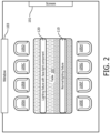
- the meeting room includes a screen 101 along a portion of a first wall thereof that may be utilized as a projector screen for presentations.
- the meeting room also includes a window 103 along a portion of a second wall thereof that provides for viewing of an outside environment located exterior to the meeting room. When present, natural daylight from the outside environment passes through the window 103 and provides lighting to the meeting room.
- the meeting room is eight chairs 105A-H positioned around a rectangular table 107.
- a lighting fixture 120 is present in the meeting room positioned above the rectangular table 107.
- the lighting fixture 120 includes at least one controller 122 in communication with at least one daylight sensor 124 and at least one presence sensor 126.
- the lighting fixture also includes a plurality of task lighting LEDs 130 in communication with the controller 122 and a plurality of face lighting LEDs 140 in communication with the controller 122.
- the task lighting LEDs 130 selectively generate a light output that is directed toward and illuminates at least a portion of the table 107.
- the face lighting LEDs 140 selectively generate a light output that is directed toward and illuminates at least a portion of the area adjacent chairs 105A-D (e.g., at least the area that would be occupied by faces of humans that are sitting in the chairs 105A-D).
- the controller 122 controls the status of task lighting LEDs 130 and face lighting LEDs 140.
- the controller 122 may be in communication with one or more LED drivers powering task lighting LEDs 130 to control whether the task lighting LEDs 130 are generating light output and, if generating light output, to optionally control one or more characteristics of the light output generated by the task lighting LEDs 130.
- the controller 122 may be in communication with one or more LED drivers powering face lighting LEDs 140 to control whether the face lighting LEDs 140 are generating light output and, if generating light output, to optionally control one or more characteristics of the light output generated by the face lighting LEDs 140.
- aspects of the controller 122 may be at least partially integrated in one or more LED drivers powering the LEDs 130 and/or 140.
- the daylight sensor 124 measures one or more values indicative of the daylight level proximal the table 107 and communicates signals indicative of such values to the controller 122.
- the presence sensor 126 measures one or more values indicative of whether a human is present in one or more of the seats 105A-D and communicates signals indicative of such values to the controller 122.
- the daylight sensor 124 may include one or more photosensors.
- the presence sensor 126 may include one or more passive infrared (PIR) sensors in some embodiments.
- the presence sensor 126 may include one or more sensors detecting changes in coded light generated by the lighting fixture 120 (e.g ., change in coded light generated by the face lighting LEDs 140).
- the presence sensor 126 may detect changes in reflected coded light generated by face lighting LEDs 140 when a human is sitting in one of the chairs 105A-D compared to when nobody is sitting in the chairs 105A-D.
- the face lighting LEDs 140 may optionally generate a plurality of coded light transmissions to determine which chair or group of chairs 105A-D is occupied.
- those LEDs of face lighting LEDs 140 generating light output that is directed toward chair 105A may generate a first coded light
- those LEDs of face lighting LEDs 140 generating light output that is directed toward chair 105B may generate a second coded light
- those LEDs of face lighting LEDs 140 generating light output that is directed toward chair 105C may generate a third coded light
- those LEDs of face lighting LEDs 140 generating light output that is directed toward chair 105D may generate a fourth coded light.
- Each coded light may be individually monitored for changes by one or more sensors to determine which of chairs 105A-D are occupied.
- the presence sensor 126 may include one or more video cameras such as an infrared video camera.
- the controller 122, the daylight sensor 124, and the presence sensor 126 may be integrated as a cohesive part of the lighting fixture 120 in some embodiments.
- the daylight sensor 124 may have exposure to the environment exterior of the lighting fixture 120 and face generally toward the table 107 under lighting fixture 120 and/or generally toward the window 103 to enable sensing of light levels proximal the table 107.
- the presence sensor 126 may have exposure to the environment exterior of the lighting fixture 120 and the presence sensor 126 may be directed toward one or more of chairs 105A-D to enable sensing of a human presence in such one or more chairs 105A-D.
- the daylight sensor 124 and/or the presence sensor 126 may be physically separated from other components of the lighting fixture 120.
- the daylight sensor 124 may be placed on the table 107, integrated into the table 107, or placed on a ceiling of the meeting room.
- the presence sensor 126 may be placed in the chairs 105A-D or placed on a ceiling of the meeting room.
- a lighting fixture 110 without a face lighting component is also present in the meeting room positioned above the rectangular table 107.
- the lighting fixture 110 may be controlled independently of the lighting fixture 120.
- the lighting fixture 110 may be manually controlled via a dimming switch.
- the lighting fixture 110 may include its own daylight sensor and adjust its light output dependent on readings from that daylight sensor.
- the lighting fixture 110 and the lighting fixture 120 may be cooperatively controlled.
- the lighting fixtures 110, 120 may be in network communication with one another and may share daylight sensor readings and/or light settings.
- no artificial light is present in the meeting room and the lighting fixture 120 is switched off and the lighting fixture 110 is also switched off.
- This may be the desired state, for example, when nobody is present in the meeting room and/or when a presentation is being presented on the screen 103.
- a user interface e.g., a control panel
- the lighting fixtures 110, 120 may additionally or alternatively be in the state of FIG. 1 in response to no human presence being detected in the room by one or more presence sensors (e.g ., presence sensor 126).
- a task lighting component of the lighting fixture 120 is switched on and the lighting fixture 110 is switched off.
- the task lighting LEDs 130 of the lighting fixture 120 are providing desired illumination to the table 107.
- the daylight sensor 124 may measure the light level on the table 107 (or alternatively may measure the light level elsewhere in the meeting room) and the controller 122 adjust the light output intensity of the task lighting LEDs 130 to maintain the light level at a desired level.
- the light output of one or more of the LEDs 130 may be adjusted based on values from the daylight sensor 124 to maintain the light level on table 107 at approximately 500 lux.
- a user interface e.g ., a control panel
- the controller 122 will automatically place the lighting fixture 120 in the state of FIG. 2 based on readings from presence sensor 126 and/or daylight sensor 124.
- Lighting fixture 110 may additionally or alternatively be illuminated. For example, in some embodiments if lighting fixture 110 is illuminated it may be unnecessary to illuminate task lighting LEDs 130 as brightly and/or to even activate task lighting LEDs 130 at all.
- the task lighting LEDs 130 of the lighting fixture 120 are switched off, the face lighting LEDs 140 of the lighting fixture 120 are switched on, and the lighting fixture 110 is switched off. Desired illumination is being provided to the table 107 via window 103.
- the daylight sensor 124 may measure the light level on the table 107 (or alternatively may measure the light level elsewhere in the meeting room) to enable the controller 122 to determine whether further illumination via task lighting LEDs 130 is required. Also, the daylight sensor 124 may measure the light level on the table 107 to enable the controller 122 to determine when light intensity from window 103 is sufficient to activate face lighting LEDs 140.
- the controller 122 may additionally or alternatively look at the status and characteristics of light output from task lighting LEDs 130 and/or lighting fixture 110 ( e.g., to deduce the contribution from window 103) and/or other daylight sensor ( e.g ., aimed directly at window 103).
- the face lighting LEDs 140 are generating a face light output generally indicated by shaded rectangle 141.
- the face light output is directed toward the area adjacent chairs 105A-D ( e.g ., at least the area that would be occupied by faces of humans that are sitting in the chairs 105A-D). The state of FIG.
- 3 may be the desired state when individuals are sitting in one or more of the chairs 105A-D and daylight is provided through window 103 to an extent that, absent lighting from face lighting LEDs 140, would cause high contrast between entering daylight from the window 103 and the front view of the faces of the individuals sitting in the chairs 105A-D to make viewing of those faces difficult for another individual ( e.g ., an individual in any one of chairs 105E-H).
- the face light output generated by face lighting LEDs 140 may be diffuse to minimize glare to individuals seated in chairs 105A-D.
- the face light output may have a beam angle that restricts the light output generally to areas that would be occupied by the individuals seated in chairs 105A-D. Such a beam angle may enable a substantial portion of the lumen output of the task lighting LEDs 130 to be utilized for illuminating individuals' faces seated in chairs 105A-D.
- only certain of the face lighting LEDs 130 may be illuminated to only provide illumination toward those chairs 105A-D that are actually occupied by a human.
- the light directed at a single of the chairs 105A-D may be directed at multiple portions of a person's face (e.g ., the left side and right side), to increase the modeling of the face (the way the shapes and shadows are visible).
- at least two distinct diffuse face lighting components may be directed toward an individual's face (e.g ., two components primarily directed about two distinct axis spaced apart from one another and/or nonparallel to one another).
- the light output of the face light output may be set as desired.
- the light output intensity of the face light output may be set to achieve approximately 200 lux at a face of an individual sitting in one of the chairs 105A-D.
- the light output intensity of the face light output may be set to achieve a lux value at a face of an individual sitting in one of the chairs 105A-D that is less than or equal to approximately 25% of the lux value at the table 107.
- the controller 122 may utilize input from daylight sensor 124 to adjust the light output intensity of the face lighting LEDs 140 to generate a lux a predetermined distance away that is approximately 20% of the measured lux via daylight sensor 124.
- the light output intensity of the face light output may additionally or alternatively be adjustable (e.g ., from 0% to 25% in an energy savings mode) by a user via a user interface (e.g ., a dimmer) and/or automatically ( e.g ., proportional to brightness of daylight provided through window 103).
- the energy savings mode may be utilized during certain time periods (e.g ., as set by a user via a user interface, during periods of traditionally high energy demand), may be utilized in response to a demand response event communicated to the controller 122, and/or may be utilized as one of a plurality of user selectable modes.
- the light output of the face light output may also be set to a light therapy mode.
- the light output intensity of the face light output may be set to achieve a lux value at a face of an individual sitting in one of the chairs 105A-D that is greater than the light output intensity in the energy savings mode.
- Other light output characteristics of the face light output may additionally or alternatively be altered in therapy mode or energy savings mode such as, for example, color, beam angle, and/or frequency.
- the light therapy mode may be utilized in situations where it is desired to reduce contrast between entering daylight from the window 103 and the front view of the faces of the individuals sitting in the chairs 105A-D to make viewing of those faces less difficult.
- the light therapy mode may be activated without regard to the daylight from the window 103.
- only certain of the face lighting LEDs 130 may be illuminated to only provide illumination toward those chairs 105A-D that are actually occupied by a human. For example, if only chairs 105A and 105D are occupied ( e.g ., as determined by presence sensor 126) then only those LEDs of face lighting LEDs 140 which generate a light output toward chairs 105A and 105D may be illuminated.
- the light output intensity of the face light output may be set to achieve a lux value at a face of an individual sitting in one of the chairs 105A-D that is less than or equal to approximately 200% of the lux value at the table 107.
- the controller 122 may utilize input from daylight sensor 124 to adjust the light output intensity of the face lighting LEDs 140 to generate a lux a predetermined distance away that is approximately 200% of the measured lux via daylight sensor 124.
- the light output intensity of the face light output during the light therapy mode may additionally or alternatively be adjustable ( e.g ., from 0% to 200%) by a user via a user interface ( e.g ., a GUI) and/or automatically.
- the light therapy mode may be utilized during certain time periods (e.g ., as set by a user via a user interface, during periods traditionally utilized for light therapy, at the beginning of a meeting). In some embodiments the light therapy mode may be utilized as one of a plurality of user selectable modes.
- the light therapy mode may be utilized in response to feedback from one or more sensors.
- one or more bio-feedback signals from one or more individuals may be utilized to automatically switch on light therapy mode for the face lighting LEDs directed at those individual(s).
- bio-feedback signals based on an analysis of video images of the eye-movements and/or pupil size may be analyzed. Accordingly, if an individual person sitting at the table is getting less concentrated or sleepy, the face lighting directed at such individual can be altered ( e.g ., switched to one or more higher intensities, switched to one or more different colors - optionally while maintaining face lighting levels directed at other individual(s) at another level ( e.g.
- lighting therapy may otherwise be individually tailored for one or more individuals.
- a user interface may be utilized to set desired light therapy characteristics for certain chairs 105A-D.
- a user may have an RFID tag or other device that communicates desired light therapy settings to the controller 122.
- additional sides of the table 107 may be provided with face lighting if desired.
- face lighting may be provided toward chairs 105E-H and/or toward the chair-less ends of table 107 (where individuals might stand, or sit in additional seating).
- Such additional face lighting may be generated by face lighting LEDs 130 of lighting fixture 120 and/or from one or more additional lighting fixtures having face lighting. Any such additional lighting fixtures may optionally be in network communication with lighting fixture 120.
- FIG. 4 illustrates a side view of the meeting room with the lighting fixtures 110, 120 in a state such as that shown in FIG. 3 .
- the face lighting LEDs 140 of the lighting fixture 120 are directing face light output 106 toward the face of an individual 102 that is seated in chair 105A.
- the face light output 106 makes the face of the individual 102 more easily viewable by those on an opposite side of the table 107 and minimizes the contrast between daylight 104 entering through the window 103 and the front view of the face of the individual 102.
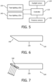
- FIG. 6 illustrates a side view of the lighting fixture 120.
- the task lighting LEDs 130 are provided on a bottom portion of the lighting fixture 120 that generally faces toward the table 107.
- the face lighting LEDs 140 are provided on a side portion of the lighting fixture that is positioned at an upward angle relative to the bottom portion.
- the mounting angle of the LEDs 140 may be selected to direct light output a desired extent peripherally of the lighting fixture 120.
- the LEDs 130 and/or 140 may be paired with one or more reflectors, diffusers, optical pieces, and/or other optical elements to achieve desired light output characteristics.
- FIG. 7 illustrates another embodiment of a lighting fixture 220.
- the lighting fixture 220 includes task lighting LEDs 230 on a bottom portion thereof and a face light component that includes a plurality of LEDs 240 that are mechanically directionally adjustable.
- the directionally adjustable LEDs 240 may enable fine tuning of the illumination to be adaptable to various environments. For example, the direction of the LEDs 240 may be adjusted to accommodate different size tables, to accommodate different lighting fixture installation positions, and/or to accommodate different seating and/or standing arrangements adjacent a table or other task area. In some embodiments, all the LEDs 240 may be uniformly adjustable. In other embodiments individual segments of the LEDs 240 may be individually adjustable. For example, multiple segments may be provided, with each of the segments directed generally toward a user segment such as a chair or group of chairs and each of the segments being individually adjustable.
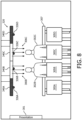
- FIG. 8 illustrates another embodiment of a meeting room having another embodiment of a lighting fixture 320.
- the meeting room includes a presentation screen 201. Inside the meeting room are chairs, four of which (305A-D) are visible and two of which (305B, 305C) have individuals 302B, 302C sitting in them. A window is also present in the meeting room. The window is not illustrated but is to the rear of the two individuals 202B, 202C (in other words, in a direction out of the page). Natural daylight from the outside environment may pass through the window and provide lighting to portions of the meeting room.
- the lighting fixture 320 includes face lighting including a first face lighting segment 340A, a second face lighting segment 340B, a third face lighting segment 340C, and a fourth face lighting segment 340D.
- face lighting including a first face lighting segment 340A, a second face lighting segment 340B, a third face lighting segment 340C, and a fourth face lighting segment 340D.
- Four presence sensors 326A, 326B, 326C, and 326D are also provided, each being paired with a respective of the face lighting segments 340A-D.
- the presence sensor 326A monitors for presence of an individual in seat 305A
- the presence sensor 326B monitors for presence of an individual in seat 305B
- the presence sensor 326C monitors for presence of an individual in seat 305C
- the presence sensor 326D monitors for presence of an individual in seat 305D.
- the lighting segments 340A and 340D are not generating a light output. Since individuals 302B and 302C are present in seats 305A and 305D, lighting segments 340B and 340C are illuminated and directing light output 306B and 306C toward the faces of the individuals 302B, 302C.
- One or more controllers may be in communication with the presence sensors 326A-D and utilize output therefrom to control which face lighting segments 340A-D are illuminated.
- the segments 340A-D may optionally be operable in an energy savings mode and/or a light therapy mode as described herein for example with respect to lighting fixture 120.
- the face lighting segments 340A-D may additionally or alternatively optionally be adjusted and/or activated based at least in part on readings from one or more daylight sensors as described herein for example with respect to lighting fixture 120.
- the lighting fixture 320 may also optionally incorporate a task lighting component including one or more task lighting sources as described herein for example with respect to lighting fixture 120.
Landscapes
- Health & Medical Sciences (AREA)
- Physics & Mathematics (AREA)
- Nonlinear Science (AREA)
- Biomedical Technology (AREA)
- Engineering & Computer Science (AREA)
- General Physics & Mathematics (AREA)
- Optics & Photonics (AREA)
- Social Psychology (AREA)
- Nuclear Medicine, Radiotherapy & Molecular Imaging (AREA)
- Psychology (AREA)
- Hospice & Palliative Care (AREA)
- Developmental Disabilities (AREA)
- Child & Adolescent Psychology (AREA)
- Pathology (AREA)
- Psychiatry (AREA)
- Radiology & Medical Imaging (AREA)
- Life Sciences & Earth Sciences (AREA)
- Animal Behavior & Ethology (AREA)
- General Health & Medical Sciences (AREA)
- Public Health (AREA)
- Veterinary Medicine (AREA)
- Circuit Arrangement For Electric Light Sources In General (AREA)
- Optical Modulation, Optical Deflection, Nonlinear Optics, Optical Demodulation, Optical Logic Elements (AREA)
Claims (14)
- Verfahren zum Steuern einer Aufgabenbeleuchtungskomponente (130, 230) und einer Gesichtsbeleuchtungskomponente (140, 240, 340A...D) mindestens eines Beleuchtungskörpers (120, 220, 320), umfassend:Überwachen eines Lichtpegels proximal zu einem Aufgabenbereich;Bereitstellen von Aufgabenbeleuchtung von mindestens einem Beleuchtungskörper, oberhalb des Aufgabenbereichs, an den Aufgabenbereich, wenn der Lichtpegel proximal zu dem Aufgabenbereich unterhalb eines Schwellenwerts liegt;dadurch gekennzeichnet, dass es Folgendes umfasstÜberwachen jedes von einer Vielzahl von Benutzersegmenten auf menschliche Präsenz, wobei die Benutzersegmente an den Aufgabenbereich angrenzen und für die Benutzerinteraktion mit dem Aufgabenbereich verwendet werden; undBereitstellen einer Gesichtsbeleuchtung von dem mindestens einen Beleuchtungskörper, oberhalb des Aufgabenbereichs, nur an den Benutzersegment, das die menschliche Präsenz aufweist;wobei die Gesichtsbeleuchtung und die Aufgabenbeleuchtung unabhängig so einstellbar sind, dass die Aufgabenbeleuchtung von der Gesichtsbeleuchtung in mindestens einem von Intensität, spektraler Zusammensetzung und dynamischem Verhalten verschieden ist.
- Verfahren nach Anspruch 1, wobei die Aufgabenbeleuchtung von der Gesichtsbeleuchtung in mindestens einem von Intensität, spektraler Zusammensetzung und dynamischem Verhalten verschieden ist.
- Verfahren nach Anspruch 2, wobei die Eigenschaften der Gesichtsbeleuchtung unabhängig für mindestens eines der Benutzersegmente über eine Benutzerschnittstelle eingestellt werden können.
- Verfahren nach einem der vorstehenden Ansprüche, wobei als Reaktion auf das Identifizieren mindestens eines von einer vorbestimmten Intensität des eingehenden Tageslichts und einer vorbestimmten Richtung des eingehenden Tageslichts die Gesichtsbeleuchtung automatisch an die Benutzersegmente bereitgestellt wird, die sich auf der Seite des Beleuchtungskörpers befinden, von der das Tageslicht herkommt.
- Verfahren nach einem der vorstehenden Ansprüche, wobei ein Aufgabenbeleuchtungspegel der Aufgabenbeleuchtung proportional zu dem Lichtpegel nahe dem Aufgabenbereich ist.
- Verfahren nach einem der vorstehenden Ansprüche, wobei eine Herkunftsrichtung der Gesichtsbeleuchtung, die auf jedes der Benutzersegmente gerichtet ist, einstellbar ist.
- Verfahren nach einem der vorstehenden Ansprüche, wobei der Schritt des Überwachens jedes der Benutzersegmente das Überwachen von Reflexionen von codiertem Licht einschließt, das auf jedes der Benutzersegmente gerichtet ist.
- Verfahren nach einem der vorstehenden Ansprüche, wobei in einem ersten Modus die Gesichtsbeleuchtung nur an die Benutzersegmente bereitgestellt wird, die die menschliche Präsenz aufweisen und zwischen dem Aufgabenbereich und einem Fenster, das zu dem Lichtpegel beiträgt, angeordnet sind.
- Verfahren nach Anspruch 8, wobei in einem zweiten Modus die Gesichtsbeleuchtung an alle Benutzersegmente bereitgestellt wird, die die menschliche Präsenz aufweisen.
- Verfahren nach Anspruch 9, wobei in dem ersten Modus ein Verhältnis eines Gesichtsoberflächen-Lux-Wertes zu einem Aufgabenoberflächen-Lux-Wert kleiner als eins ist, wobei der Gesichtsoberflächen-Lux-Wert an einer Gesichtsoberfläche in jedem der Benutzersegmente aufgenommen wird und der Aufgabenoberflächen-Lux-Wert an der Aufgabenoberfläche aufgenommen wird, und wobei in dem zweiten Modus das Verhältnis des Gesichtsoberflächen-Lux-Wertes zu dem Aufgabenoberflächen-Lux-Wert innerhalb eines zweiten Bereichs einstellbar ist, wobei der zweite Bereich Werte größer als eins einschließt.
- Verfahren nach Anspruch 2, wobei das mindestens eine von Intensität, spektraler Zusammensetzung und dynamischem Verhalten der Gesichtsbeleuchtung und der Aufgabenbeleuchtung, die unabhängig voneinander einstellbar sind, ausgewählt sind aus der Gruppe bestehend aus: Intensität, spektraler Zusammensetzung und dynamischem Verhalten.
- Beleuchtungskörper (120), umfassend:eine Aufgabenbeleuchtungskomponente (130, 230), umfassend eine Vielzahl von Aufgabenbeleuchtungs-LEDs, die selektiv eine Aufgabenlichtausgabe in einer Abwärtsrichtung unterhalb des Beleuchtungskörpers (120) bereitstellen;eine Gesichtsbeleuchtungskomponente (140, 240, 340A...D), umfassend eine Vielzahl von Gesichtsbeleuchtungs-LEDs, die eine Gesichtslichtausgabe in einer Richtung peripher des Beleuchtungskörpers bereitstellen; undmindestens eine Steuerung (122), die konfiguriert ist, um Tageslichterfassungssignale und Benutzersegment-Präsenzerfassungssignale zu empfangen, wobei die Benutzersegment-Präsenzerfassungssignale angeben, welche von einer Vielzahl von Benutzersegmenten, die an einen Aufgabenbereich angrenzen, von einem Menschen besetzt sind, wobei die mindestens eine Steuerung (122) konfiguriert ist, um eine Vielzahl der Aufgabenbeleuchtungs-LEDs zu aktivieren, wenn die Tageslichterfassungssignale einen Lichtpegel unterhalb eines Schwellenwerts anzeigen, und um nur die Gesichtsbeleuchtungs-LEDs zu aktivieren, die die Gesichtsbeleuchtungsausgabe in eine Richtung zu den Benutzersegmenten bereitstellen, die die menschliche Präsenz aufweisen.
- Beleuchtungskörper (120) nach Anspruch 12, ferner umfassend mindestens einen Tageslichtsensor (124) zum Bereitstellen der Tageslichtsensorsignale und mindestens eines Anwesenheitssensors (126) zum Bereitstellen der Benutzerpräsenzsensorsignale.
- Beleuchtungssystem, umfassend mindestens einen Beleuchtungskörper (120, 220, 320) nach Anspruch 12 und mindestens einen Tageslichtsensor (124) zum Bereitstellen der Tageslichtsensorsignale und mindestens einen Anwesenheitssensor (126) zum Bereitstellen der Benutzerpräsenzsensorsignale.
Applications Claiming Priority (2)
| Application Number | Priority Date | Filing Date | Title |
|---|---|---|---|
| US201261622596P | 2012-04-11 | 2012-04-11 | |
| PCT/IB2013/052735 WO2013153495A1 (en) | 2012-04-11 | 2013-04-05 | Lighting methods and apparatus with selectively applied face lighting component |
Publications (2)
| Publication Number | Publication Date |
|---|---|
| EP2837271A1 EP2837271A1 (de) | 2015-02-18 |
| EP2837271B1 true EP2837271B1 (de) | 2024-03-06 |
Family
ID=48579142
Family Applications (1)
| Application Number | Title | Priority Date | Filing Date |
|---|---|---|---|
| EP13727975.8A Active EP2837271B1 (de) | 2012-04-11 | 2013-04-05 | Vorrichtung und verfahren zur selektiver beleuchtung von gesichter |
Country Status (7)
| Country | Link |
|---|---|
| US (2) | US9392651B2 (de) |
| EP (1) | EP2837271B1 (de) |
| JP (1) | JP6173432B2 (de) |
| CN (1) | CN104206025B (de) |
| ES (1) | ES2978793T3 (de) |
| RU (1) | RU2627029C2 (de) |
| WO (1) | WO2013153495A1 (de) |
Families Citing this family (19)
| Publication number | Priority date | Publication date | Assignee | Title |
|---|---|---|---|---|
| US10813199B2 (en) * | 2012-02-07 | 2020-10-20 | Dolan Designs Incorporated | Combined lighting device with an integrated dimming control system |
| WO2014064587A1 (en) * | 2012-10-26 | 2014-05-01 | Koninklijke Philips N.V. | Lighting methods for providing personalized lighting to users positioned proximal to one another |
| US9992841B2 (en) | 2013-04-19 | 2018-06-05 | Lutron Electronics Co., Inc. | Systems and methods for controlling color temperature |
| CA2875014A1 (en) | 2013-12-17 | 2015-06-17 | Ephesus Lighting, Inc. | Lens structure for high intensity led fixture |
| DE102014207632A1 (de) * | 2014-04-23 | 2015-10-29 | Zumtobel Lighting Gmbh | Anordnung und Verfahren zur Beleuchtung von Arbeitsbereichen |
| US9681525B2 (en) * | 2015-04-02 | 2017-06-13 | Elwha Llc | Systems and methods for controlling lighting based on a display |
| US9678494B2 (en) * | 2015-04-02 | 2017-06-13 | Elwha Llc | Systems and methods for controlling lighting based on a display |
| US10185205B2 (en) * | 2015-07-13 | 2019-01-22 | The Regents Of The University Of Colorado, A Body | CMOS compatible optical modulators |
| DE202016100586U1 (de) * | 2016-02-05 | 2017-05-10 | Zumtobel Lighting Gmbh | Lichtbandsystem mit mehreren ansteuerbaren Lichtbandmodulen |
| EP3337297A1 (de) * | 2016-12-15 | 2018-06-20 | Thomson Licensing | Vorrichtung und verfahren zur steuerung der beleuchtungsbedingungen in einem raum |
| DE102017205449A1 (de) * | 2017-03-30 | 2018-10-04 | Zumtobel Lighting Gmbh | Leuchte |
| US11099540B2 (en) | 2017-09-15 | 2021-08-24 | Kohler Co. | User identity in household appliances |
| US10887125B2 (en) | 2017-09-15 | 2021-01-05 | Kohler Co. | Bathroom speaker |
| US11093554B2 (en) | 2017-09-15 | 2021-08-17 | Kohler Co. | Feedback for water consuming appliance |
| US11314214B2 (en) | 2017-09-15 | 2022-04-26 | Kohler Co. | Geographic analysis of water conditions |
| WO2019068665A1 (en) | 2017-10-05 | 2019-04-11 | Signify Holding B.V. | CIRCADIAN LIGHTING ARRANGEMENT |
| WO2019105880A1 (en) * | 2017-11-28 | 2019-06-06 | Signify Holding B.V. | Lighting fixture design |
| CN108156707B (zh) * | 2017-12-25 | 2020-04-24 | 安徽极光照明工程有限公司 | 一种基于传感监测控制的led阅读灯装置系统 |
| JP2022151862A (ja) * | 2021-03-25 | 2022-10-07 | 國立陽明交通大學 | 睡眠障害、認知及び/又は神経障害を改善する周囲照明 |
Family Cites Families (26)
| Publication number | Priority date | Publication date | Assignee | Title |
|---|---|---|---|---|
| JP2866774B2 (ja) * | 1992-11-09 | 1999-03-08 | 株式会社東海理化電機製作所 | 物体検出装置 |
| DE4413070A1 (de) * | 1994-04-15 | 1995-10-19 | Thorn Licht Gmbh | Arbeitsplatzleuchte |
| US20040052076A1 (en) * | 1997-08-26 | 2004-03-18 | Mueller George G. | Controlled lighting methods and apparatus |
| JP3788099B2 (ja) * | 1999-03-31 | 2006-06-21 | 三菱電機株式会社 | 照明システム |
| US6665805B1 (en) * | 1999-12-27 | 2003-12-16 | Intel Corporation | Method and apparatus for real time monitoring of user presence to prolong a portable computer battery operation time |
| JP2006507641A (ja) * | 2002-11-22 | 2006-03-02 | コーニンクレッカ フィリップス エレクトロニクス エヌ ヴィ | 光源を制御するシステム及び方法と照明配置 |
| RU2325047C1 (ru) * | 2004-02-02 | 2008-05-20 | Ботем Электроник Ко., Лтд. | Энергосберегающий выключатель |
| WO2006038169A1 (en) * | 2004-10-05 | 2006-04-13 | Koninklijke Philips Electronics N.V. | Interactive lighting system |
| EP1979672B1 (de) | 2006-01-16 | 2017-09-13 | Philips Lighting Holding B.V. | Leuchtenmodul und beleuchtungsvorrichtung mit einem solchen leuchtenmodul |
| JP2008005416A (ja) | 2006-06-26 | 2008-01-10 | Toshiba Corp | 信号合成装置,信号送信装置,および信号受信装置 |
| TWI334037B (en) * | 2006-09-04 | 2010-12-01 | Ind Tech Res Inst | Electro-optical modulator with curving resonantor |
| CN101675379B (zh) | 2007-04-17 | 2012-03-21 | 皇家飞利浦电子股份有限公司 | 光束成形设备 |
| KR101555894B1 (ko) * | 2007-05-04 | 2015-09-30 | 코닌클리케 필립스 엔.브이. | 열 관리를 위한 led 기반 설비들 및 관련 방법들 |
| CN101688912A (zh) * | 2007-06-14 | 2010-03-31 | 皇家飞利浦电子股份有限公司 | 目标定位方法、系统、标签以及用户接口设备 |
| FR2928809B1 (fr) * | 2008-03-17 | 2012-06-29 | Antoine Doublet | Systeme interactif et procede de commande d'eclairages et/ou de diffusion d'images |
| EP3541151A1 (de) * | 2008-04-14 | 2019-09-18 | Digital Lumens Incorporated | Modulare beleuchtungssysteme |
| JP2010123534A (ja) | 2008-11-21 | 2010-06-03 | Panasonic Electric Works Co Ltd | 照明システム |
| JP4621779B2 (ja) | 2009-02-17 | 2011-01-26 | シャープ株式会社 | 照明デバイスおよび該照明デバイスを使用した照明装置 |
| JP5486205B2 (ja) | 2009-03-26 | 2014-05-07 | パナソニック株式会社 | タスク用照明器具による照明方法及びタスク用照明器具 |
| JP5433291B2 (ja) * | 2009-04-24 | 2014-03-05 | パナソニック株式会社 | タスクアンビエント照明システム |
| CN101711079B (zh) * | 2009-11-24 | 2013-10-23 | 江苏大学 | 教室照明无线检测与控制装置及方法 |
| US20110270446A1 (en) * | 2010-05-03 | 2011-11-03 | Energy Eye, Inc. | Systems and methods for an environmental control system including a motorized vent covering |
| WO2013144756A2 (en) * | 2012-03-28 | 2013-10-03 | Koninklijke Philips N.V. | Methods and apparatus for operating a lighting network according to energy demand and energy supply |
| US8779669B2 (en) * | 2012-08-24 | 2014-07-15 | Abl Ip Holding Llc | Chaotic approach to control of lighting |
| WO2014064587A1 (en) * | 2012-10-26 | 2014-05-01 | Koninklijke Philips N.V. | Lighting methods for providing personalized lighting to users positioned proximal to one another |
| JP6231133B2 (ja) * | 2013-01-25 | 2017-11-15 | フィリップス ライティング ホールディング ビー ヴィ | 照明装置及び照明システム |
-
2013
- 2013-04-05 EP EP13727975.8A patent/EP2837271B1/de active Active
- 2013-04-05 RU RU2014145198A patent/RU2627029C2/ru active
- 2013-04-05 WO PCT/IB2013/052735 patent/WO2013153495A1/en not_active Ceased
- 2013-04-05 ES ES13727975T patent/ES2978793T3/es active Active
- 2013-04-05 US US14/391,287 patent/US9392651B2/en active Active
- 2013-04-05 JP JP2015505045A patent/JP6173432B2/ja active Active
- 2013-04-05 CN CN201380019272.XA patent/CN104206025B/zh active Active
- 2013-04-11 US US13/860,978 patent/US8947764B1/en active Active
Also Published As
| Publication number | Publication date |
|---|---|
| WO2013153495A1 (en) | 2013-10-17 |
| US8947764B1 (en) | 2015-02-03 |
| US9392651B2 (en) | 2016-07-12 |
| RU2014145198A (ru) | 2016-05-27 |
| ES2978793T3 (es) | 2024-09-20 |
| JP2015516657A (ja) | 2015-06-11 |
| EP2837271A1 (de) | 2015-02-18 |
| CN104206025A (zh) | 2014-12-10 |
| US20150061506A1 (en) | 2015-03-05 |
| RU2627029C2 (ru) | 2017-08-03 |
| CN104206025B (zh) | 2017-08-08 |
| JP6173432B2 (ja) | 2017-08-02 |
Similar Documents
| Publication | Publication Date | Title |
|---|---|---|
| EP2837271B1 (de) | Vorrichtung und verfahren zur selektiver beleuchtung von gesichter | |
| EP2912925B1 (de) | Beleuchtungsverfahren zur bereitstellung einer personalisierten beleuchtung für proximal zueinander positionierte benutzer | |
| EP2874701B1 (de) | Verfahren und vorrichtung zur bereitstellung personalisierter beleuchtung | |
| US10598363B2 (en) | Apparatus and method for providing downlighting and wall-washing lighting effects | |
| US12398852B2 (en) | Edgelit lighting assembly with adjustable light distribution | |
| JP2020061385A (ja) | 利用者の近さに基づいて強度が下げられた光出力を与える照明ユニット及び関連する方法 | |
| JP6291142B2 (ja) | 可撓性基板の1つ以上の長さに基づく照明制御 | |
| JP5433291B2 (ja) | タスクアンビエント照明システム | |
| US20160295672A1 (en) | Method and system for providing a dynamic lighting effect to specular and refractive objects | |
| US20180259143A1 (en) | Methods, systems and apparatus for emergency lighting | |
| CN121751439A (zh) | 灯光控制装置、方法及灯具 |
Legal Events
| Date | Code | Title | Description |
|---|---|---|---|
| PUAI | Public reference made under article 153(3) epc to a published international application that has entered the european phase |
Free format text: ORIGINAL CODE: 0009012 |
|
| 17P | Request for examination filed |
Effective date: 20141111 |
|
| AK | Designated contracting states |
Kind code of ref document: A1 Designated state(s): AL AT BE BG CH CY CZ DE DK EE ES FI FR GB GR HR HU IE IS IT LI LT LU LV MC MK MT NL NO PL PT RO RS SE SI SK SM TR |
|
| AX | Request for extension of the european patent |
Extension state: BA ME |
|
| DAX | Request for extension of the european patent (deleted) | ||
| RAP1 | Party data changed (applicant data changed or rights of an application transferred) |
Owner name: PHILIPS LIGHTING HOLDING B.V. |
|
| RIN1 | Information on inventor provided before grant (corrected) |
Inventor name: SCHLANGEN, LUCAS JOSEF MARIA Inventor name: VAN DER POEL, LUCAS LEO DESIREE Inventor name: BAAIJENS, JOHANNES PETRUS WILHELMUS |
|
| RAP1 | Party data changed (applicant data changed or rights of an application transferred) |
Owner name: PHILIPS LIGHTING HOLDING B.V. |
|
| RAP1 | Party data changed (applicant data changed or rights of an application transferred) |
Owner name: SIGNIFY HOLDING B.V. |
|
| STAA | Information on the status of an ep patent application or granted ep patent |
Free format text: STATUS: EXAMINATION IS IN PROGRESS |
|
| 17Q | First examination report despatched |
Effective date: 20190514 |
|
| REG | Reference to a national code |
Ref country code: DE Ref legal event code: R079 Free format text: PREVIOUS MAIN CLASS: H05B0037020000 Ipc: H05B0047110000 Ref country code: DE Ref legal event code: R079 Ref document number: 602013085392 Country of ref document: DE Free format text: PREVIOUS MAIN CLASS: H05B0037020000 Ipc: H05B0047110000 |
|
| GRAP | Despatch of communication of intention to grant a patent |
Free format text: ORIGINAL CODE: EPIDOSNIGR1 |
|
| STAA | Information on the status of an ep patent application or granted ep patent |
Free format text: STATUS: GRANT OF PATENT IS INTENDED |
|
| INTG | Intention to grant announced |
Effective date: 20230721 |
|
| RIC1 | Information provided on ipc code assigned before grant |
Ipc: H05B 47/115 20200101ALN20230710BHEP Ipc: H05B 47/11 20200101AFI20230710BHEP |
|
| GRAJ | Information related to disapproval of communication of intention to grant by the applicant or resumption of examination proceedings by the epo deleted |
Free format text: ORIGINAL CODE: EPIDOSDIGR1 |
|
| STAA | Information on the status of an ep patent application or granted ep patent |
Free format text: STATUS: EXAMINATION IS IN PROGRESS |
|
| GRAP | Despatch of communication of intention to grant a patent |
Free format text: ORIGINAL CODE: EPIDOSNIGR1 |
|
| STAA | Information on the status of an ep patent application or granted ep patent |
Free format text: STATUS: GRANT OF PATENT IS INTENDED |
|
| INTC | Intention to grant announced (deleted) | ||
| RIC1 | Information provided on ipc code assigned before grant |
Ipc: H05B 47/115 20200101ALN20230920BHEP Ipc: H05B 47/11 20200101AFI20230920BHEP |
|
| INTG | Intention to grant announced |
Effective date: 20231010 |
|
| GRAS | Grant fee paid |
Free format text: ORIGINAL CODE: EPIDOSNIGR3 |
|
| GRAA | (expected) grant |
Free format text: ORIGINAL CODE: 0009210 |
|
| STAA | Information on the status of an ep patent application or granted ep patent |
Free format text: STATUS: THE PATENT HAS BEEN GRANTED |
|
| AK | Designated contracting states |
Kind code of ref document: B1 Designated state(s): AL AT BE BG CH CY CZ DE DK EE ES FI FR GB GR HR HU IE IS IT LI LT LU LV MC MK MT NL NO PL PT RO RS SE SI SK SM TR |
|
| P01 | Opt-out of the competence of the unified patent court (upc) registered |
Effective date: 20240130 |
|
| REG | Reference to a national code |
Ref country code: GB Ref legal event code: FG4D |
|
| REG | Reference to a national code |
Ref country code: CH Ref legal event code: EP |
|
| REG | Reference to a national code |
Ref country code: DE Ref legal event code: R096 Ref document number: 602013085392 Country of ref document: DE |
|
| REG | Reference to a national code |
Ref country code: IE Ref legal event code: FG4D |
|
| REG | Reference to a national code |
Ref country code: SE Ref legal event code: TRGR |
|
| REG | Reference to a national code |
Ref country code: LT Ref legal event code: MG9D |
|
| PG25 | Lapsed in a contracting state [announced via postgrant information from national office to epo] |
Ref country code: LT Free format text: LAPSE BECAUSE OF FAILURE TO SUBMIT A TRANSLATION OF THE DESCRIPTION OR TO PAY THE FEE WITHIN THE PRESCRIBED TIME-LIMIT Effective date: 20240306 |
|
| REG | Reference to a national code |
Ref country code: NL Ref legal event code: MP Effective date: 20240306 |
|
| PG25 | Lapsed in a contracting state [announced via postgrant information from national office to epo] |
Ref country code: GR Free format text: LAPSE BECAUSE OF FAILURE TO SUBMIT A TRANSLATION OF THE DESCRIPTION OR TO PAY THE FEE WITHIN THE PRESCRIBED TIME-LIMIT Effective date: 20240607 |
|
| PG25 | Lapsed in a contracting state [announced via postgrant information from national office to epo] |
Ref country code: HR Free format text: LAPSE BECAUSE OF FAILURE TO SUBMIT A TRANSLATION OF THE DESCRIPTION OR TO PAY THE FEE WITHIN THE PRESCRIBED TIME-LIMIT Effective date: 20240306 Ref country code: RS Free format text: LAPSE BECAUSE OF FAILURE TO SUBMIT A TRANSLATION OF THE DESCRIPTION OR TO PAY THE FEE WITHIN THE PRESCRIBED TIME-LIMIT Effective date: 20240606 |
|
| PG25 | Lapsed in a contracting state [announced via postgrant information from national office to epo] |
Ref country code: RS Free format text: LAPSE BECAUSE OF FAILURE TO SUBMIT A TRANSLATION OF THE DESCRIPTION OR TO PAY THE FEE WITHIN THE PRESCRIBED TIME-LIMIT Effective date: 20240606 Ref country code: NO Free format text: LAPSE BECAUSE OF FAILURE TO SUBMIT A TRANSLATION OF THE DESCRIPTION OR TO PAY THE FEE WITHIN THE PRESCRIBED TIME-LIMIT Effective date: 20240606 Ref country code: LT Free format text: LAPSE BECAUSE OF FAILURE TO SUBMIT A TRANSLATION OF THE DESCRIPTION OR TO PAY THE FEE WITHIN THE PRESCRIBED TIME-LIMIT Effective date: 20240306 Ref country code: HR Free format text: LAPSE BECAUSE OF FAILURE TO SUBMIT A TRANSLATION OF THE DESCRIPTION OR TO PAY THE FEE WITHIN THE PRESCRIBED TIME-LIMIT Effective date: 20240306 Ref country code: GR Free format text: LAPSE BECAUSE OF FAILURE TO SUBMIT A TRANSLATION OF THE DESCRIPTION OR TO PAY THE FEE WITHIN THE PRESCRIBED TIME-LIMIT Effective date: 20240607 Ref country code: FI Free format text: LAPSE BECAUSE OF FAILURE TO SUBMIT A TRANSLATION OF THE DESCRIPTION OR TO PAY THE FEE WITHIN THE PRESCRIBED TIME-LIMIT Effective date: 20240306 Ref country code: BG Free format text: LAPSE BECAUSE OF FAILURE TO SUBMIT A TRANSLATION OF THE DESCRIPTION OR TO PAY THE FEE WITHIN THE PRESCRIBED TIME-LIMIT Effective date: 20240306 |
|
| REG | Reference to a national code |
Ref country code: AT Ref legal event code: MK05 Ref document number: 1664795 Country of ref document: AT Kind code of ref document: T Effective date: 20240306 |
|
| PG25 | Lapsed in a contracting state [announced via postgrant information from national office to epo] |
Ref country code: LV Free format text: LAPSE BECAUSE OF FAILURE TO SUBMIT A TRANSLATION OF THE DESCRIPTION OR TO PAY THE FEE WITHIN THE PRESCRIBED TIME-LIMIT Effective date: 20240306 |
|
| PG25 | Lapsed in a contracting state [announced via postgrant information from national office to epo] |
Ref country code: NL Free format text: LAPSE BECAUSE OF FAILURE TO SUBMIT A TRANSLATION OF THE DESCRIPTION OR TO PAY THE FEE WITHIN THE PRESCRIBED TIME-LIMIT Effective date: 20240306 |
|
| REG | Reference to a national code |
Ref country code: ES Ref legal event code: FG2A Ref document number: 2978793 Country of ref document: ES Kind code of ref document: T3 Effective date: 20240920 |
|
| PG25 | Lapsed in a contracting state [announced via postgrant information from national office to epo] |
Ref country code: NL Free format text: LAPSE BECAUSE OF FAILURE TO SUBMIT A TRANSLATION OF THE DESCRIPTION OR TO PAY THE FEE WITHIN THE PRESCRIBED TIME-LIMIT Effective date: 20240306 |
|
| PG25 | Lapsed in a contracting state [announced via postgrant information from national office to epo] |
Ref country code: IS Free format text: LAPSE BECAUSE OF FAILURE TO SUBMIT A TRANSLATION OF THE DESCRIPTION OR TO PAY THE FEE WITHIN THE PRESCRIBED TIME-LIMIT Effective date: 20240706 |
|
| PG25 | Lapsed in a contracting state [announced via postgrant information from national office to epo] |
Ref country code: SM Free format text: LAPSE BECAUSE OF FAILURE TO SUBMIT A TRANSLATION OF THE DESCRIPTION OR TO PAY THE FEE WITHIN THE PRESCRIBED TIME-LIMIT Effective date: 20240306 Ref country code: PT Free format text: LAPSE BECAUSE OF FAILURE TO SUBMIT A TRANSLATION OF THE DESCRIPTION OR TO PAY THE FEE WITHIN THE PRESCRIBED TIME-LIMIT Effective date: 20240708 |
|
| PG25 | Lapsed in a contracting state [announced via postgrant information from national office to epo] |
Ref country code: EE Free format text: LAPSE BECAUSE OF FAILURE TO SUBMIT A TRANSLATION OF THE DESCRIPTION OR TO PAY THE FEE WITHIN THE PRESCRIBED TIME-LIMIT Effective date: 20240306 Ref country code: CZ Free format text: LAPSE BECAUSE OF FAILURE TO SUBMIT A TRANSLATION OF THE DESCRIPTION OR TO PAY THE FEE WITHIN THE PRESCRIBED TIME-LIMIT Effective date: 20240306 |
|
| PG25 | Lapsed in a contracting state [announced via postgrant information from national office to epo] |
Ref country code: AT Free format text: LAPSE BECAUSE OF FAILURE TO SUBMIT A TRANSLATION OF THE DESCRIPTION OR TO PAY THE FEE WITHIN THE PRESCRIBED TIME-LIMIT Effective date: 20240306 |
|
| PG25 | Lapsed in a contracting state [announced via postgrant information from national office to epo] |
Ref country code: PL Free format text: LAPSE BECAUSE OF FAILURE TO SUBMIT A TRANSLATION OF THE DESCRIPTION OR TO PAY THE FEE WITHIN THE PRESCRIBED TIME-LIMIT Effective date: 20240306 |
|
| PG25 | Lapsed in a contracting state [announced via postgrant information from national office to epo] |
Ref country code: SK Free format text: LAPSE BECAUSE OF FAILURE TO SUBMIT A TRANSLATION OF THE DESCRIPTION OR TO PAY THE FEE WITHIN THE PRESCRIBED TIME-LIMIT Effective date: 20240306 |
|
| PG25 | Lapsed in a contracting state [announced via postgrant information from national office to epo] |
Ref country code: SM Free format text: LAPSE BECAUSE OF FAILURE TO SUBMIT A TRANSLATION OF THE DESCRIPTION OR TO PAY THE FEE WITHIN THE PRESCRIBED TIME-LIMIT Effective date: 20240306 Ref country code: SK Free format text: LAPSE BECAUSE OF FAILURE TO SUBMIT A TRANSLATION OF THE DESCRIPTION OR TO PAY THE FEE WITHIN THE PRESCRIBED TIME-LIMIT Effective date: 20240306 Ref country code: RO Free format text: LAPSE BECAUSE OF FAILURE TO SUBMIT A TRANSLATION OF THE DESCRIPTION OR TO PAY THE FEE WITHIN THE PRESCRIBED TIME-LIMIT Effective date: 20240306 Ref country code: PT Free format text: LAPSE BECAUSE OF FAILURE TO SUBMIT A TRANSLATION OF THE DESCRIPTION OR TO PAY THE FEE WITHIN THE PRESCRIBED TIME-LIMIT Effective date: 20240708 Ref country code: PL Free format text: LAPSE BECAUSE OF FAILURE TO SUBMIT A TRANSLATION OF THE DESCRIPTION OR TO PAY THE FEE WITHIN THE PRESCRIBED TIME-LIMIT Effective date: 20240306 Ref country code: IS Free format text: LAPSE BECAUSE OF FAILURE TO SUBMIT A TRANSLATION OF THE DESCRIPTION OR TO PAY THE FEE WITHIN THE PRESCRIBED TIME-LIMIT Effective date: 20240706 Ref country code: EE Free format text: LAPSE BECAUSE OF FAILURE TO SUBMIT A TRANSLATION OF THE DESCRIPTION OR TO PAY THE FEE WITHIN THE PRESCRIBED TIME-LIMIT Effective date: 20240306 Ref country code: CZ Free format text: LAPSE BECAUSE OF FAILURE TO SUBMIT A TRANSLATION OF THE DESCRIPTION OR TO PAY THE FEE WITHIN THE PRESCRIBED TIME-LIMIT Effective date: 20240306 Ref country code: AT Free format text: LAPSE BECAUSE OF FAILURE TO SUBMIT A TRANSLATION OF THE DESCRIPTION OR TO PAY THE FEE WITHIN THE PRESCRIBED TIME-LIMIT Effective date: 20240306 |
|
| REG | Reference to a national code |
Ref country code: CH Ref legal event code: PL |
|
| REG | Reference to a national code |
Ref country code: DE Ref legal event code: R097 Ref document number: 602013085392 Country of ref document: DE |
|
| PG25 | Lapsed in a contracting state [announced via postgrant information from national office to epo] |
Ref country code: LU Free format text: LAPSE BECAUSE OF NON-PAYMENT OF DUE FEES Effective date: 20240405 |
|
| REG | Reference to a national code |
Ref country code: BE Ref legal event code: MM Effective date: 20240430 |
|
| PG25 | Lapsed in a contracting state [announced via postgrant information from national office to epo] |
Ref country code: LU Free format text: LAPSE BECAUSE OF NON-PAYMENT OF DUE FEES Effective date: 20240405 |
|
| PG25 | Lapsed in a contracting state [announced via postgrant information from national office to epo] |
Ref country code: MC Free format text: LAPSE BECAUSE OF FAILURE TO SUBMIT A TRANSLATION OF THE DESCRIPTION OR TO PAY THE FEE WITHIN THE PRESCRIBED TIME-LIMIT Effective date: 20240306 |
|
| PLBE | No opposition filed within time limit |
Free format text: ORIGINAL CODE: 0009261 |
|
| STAA | Information on the status of an ep patent application or granted ep patent |
Free format text: STATUS: NO OPPOSITION FILED WITHIN TIME LIMIT |
|
| PG25 | Lapsed in a contracting state [announced via postgrant information from national office to epo] |
Ref country code: DK Free format text: LAPSE BECAUSE OF FAILURE TO SUBMIT A TRANSLATION OF THE DESCRIPTION OR TO PAY THE FEE WITHIN THE PRESCRIBED TIME-LIMIT Effective date: 20240306 |
|
| PG25 | Lapsed in a contracting state [announced via postgrant information from national office to epo] |
Ref country code: BE Free format text: LAPSE BECAUSE OF NON-PAYMENT OF DUE FEES Effective date: 20240430 |
|
| PG25 | Lapsed in a contracting state [announced via postgrant information from national office to epo] |
Ref country code: MC Free format text: LAPSE BECAUSE OF FAILURE TO SUBMIT A TRANSLATION OF THE DESCRIPTION OR TO PAY THE FEE WITHIN THE PRESCRIBED TIME-LIMIT Effective date: 20240306 Ref country code: DK Free format text: LAPSE BECAUSE OF FAILURE TO SUBMIT A TRANSLATION OF THE DESCRIPTION OR TO PAY THE FEE WITHIN THE PRESCRIBED TIME-LIMIT Effective date: 20240306 Ref country code: BE Free format text: LAPSE BECAUSE OF NON-PAYMENT OF DUE FEES Effective date: 20240430 Ref country code: CH Free format text: LAPSE BECAUSE OF NON-PAYMENT OF DUE FEES Effective date: 20240430 |
|
| 26N | No opposition filed |
Effective date: 20241209 |
|
| PG25 | Lapsed in a contracting state [announced via postgrant information from national office to epo] |
Ref country code: IE Free format text: LAPSE BECAUSE OF NON-PAYMENT OF DUE FEES Effective date: 20240405 |
|
| PG25 | Lapsed in a contracting state [announced via postgrant information from national office to epo] |
Ref country code: SI Free format text: LAPSE BECAUSE OF FAILURE TO SUBMIT A TRANSLATION OF THE DESCRIPTION OR TO PAY THE FEE WITHIN THE PRESCRIBED TIME-LIMIT Effective date: 20240306 |
|
| PGFP | Annual fee paid to national office [announced via postgrant information from national office to epo] |
Ref country code: DE Payment date: 20250626 Year of fee payment: 13 |
|
| PGFP | Annual fee paid to national office [announced via postgrant information from national office to epo] |
Ref country code: ES Payment date: 20250513 Year of fee payment: 13 |
|
| PGFP | Annual fee paid to national office [announced via postgrant information from national office to epo] |
Ref country code: IT Payment date: 20250422 Year of fee payment: 13 |
|
| PGFP | Annual fee paid to national office [announced via postgrant information from national office to epo] |
Ref country code: FR Payment date: 20250424 Year of fee payment: 13 |
|
| PGFP | Annual fee paid to national office [announced via postgrant information from national office to epo] |
Ref country code: SE Payment date: 20250424 Year of fee payment: 13 |
|
| PG25 | Lapsed in a contracting state [announced via postgrant information from national office to epo] |
Ref country code: CY Free format text: LAPSE BECAUSE OF FAILURE TO SUBMIT A TRANSLATION OF THE DESCRIPTION OR TO PAY THE FEE WITHIN THE PRESCRIBED TIME-LIMIT; INVALID AB INITIO Effective date: 20130405 |
|
| PG25 | Lapsed in a contracting state [announced via postgrant information from national office to epo] |
Ref country code: HU Free format text: LAPSE BECAUSE OF FAILURE TO SUBMIT A TRANSLATION OF THE DESCRIPTION OR TO PAY THE FEE WITHIN THE PRESCRIBED TIME-LIMIT; INVALID AB INITIO Effective date: 20130405 |
|
| PG25 | Lapsed in a contracting state [announced via postgrant information from national office to epo] |
Ref country code: TR Free format text: LAPSE BECAUSE OF FAILURE TO SUBMIT A TRANSLATION OF THE DESCRIPTION OR TO PAY THE FEE WITHIN THE PRESCRIBED TIME-LIMIT Effective date: 20240306 |
|
| PGFP | Annual fee paid to national office [announced via postgrant information from national office to epo] |
Ref country code: GB Payment date: 20260226 Year of fee payment: 14 |