EP2837352A1 - Dispositif supplémentaire pour appareils de nettoyage à ultrasons, dispositif de commande pour un appareil à ultrasons et procédé de déplacement actif d'au moins une zone d'un instrument médical - Google Patents
Dispositif supplémentaire pour appareils de nettoyage à ultrasons, dispositif de commande pour un appareil à ultrasons et procédé de déplacement actif d'au moins une zone d'un instrument médical Download PDFInfo
- Publication number
- EP2837352A1 EP2837352A1 EP13180744.8A EP13180744A EP2837352A1 EP 2837352 A1 EP2837352 A1 EP 2837352A1 EP 13180744 A EP13180744 A EP 13180744A EP 2837352 A1 EP2837352 A1 EP 2837352A1
- Authority
- EP
- European Patent Office
- Prior art keywords
- medical instrument
- adapter
- coupling element
- housing
- movement
- Prior art date
- Legal status (The legal status is an assumption and is not a legal conclusion. Google has not performed a legal analysis and makes no representation as to the accuracy of the status listed.)
- Withdrawn
Links
- 238000002604 ultrasonography Methods 0.000 title claims abstract description 23
- 238000000034 method Methods 0.000 title claims description 9
- 238000004140 cleaning Methods 0.000 title description 12
- 230000008878 coupling Effects 0.000 claims abstract description 90
- 238000010168 coupling process Methods 0.000 claims abstract description 90
- 238000005859 coupling reaction Methods 0.000 claims abstract description 90
- 238000011010 flushing procedure Methods 0.000 claims description 15
- 239000007788 liquid Substances 0.000 claims description 10
- 238000010926 purge Methods 0.000 claims description 5
- XLYOFNOQVPJJNP-UHFFFAOYSA-N water Substances O XLYOFNOQVPJJNP-UHFFFAOYSA-N 0.000 claims 1
- 230000007246 mechanism Effects 0.000 description 20
- 230000000694 effects Effects 0.000 description 9
- 239000004033 plastic Substances 0.000 description 6
- 238000004506 ultrasonic cleaning Methods 0.000 description 6
- 239000012530 fluid Substances 0.000 description 4
- 230000002262 irrigation Effects 0.000 description 4
- 238000003973 irrigation Methods 0.000 description 4
- 229910052751 metal Inorganic materials 0.000 description 4
- 239000002184 metal Substances 0.000 description 4
- 239000002245 particle Substances 0.000 description 4
- 230000009471 action Effects 0.000 description 3
- 230000005540 biological transmission Effects 0.000 description 3
- 238000007792 addition Methods 0.000 description 2
- 230000006870 function Effects 0.000 description 2
- 230000008569 process Effects 0.000 description 2
- RYGMFSIKBFXOCR-UHFFFAOYSA-N Copper Chemical compound [Cu] RYGMFSIKBFXOCR-UHFFFAOYSA-N 0.000 description 1
- RTAQQCXQSZGOHL-UHFFFAOYSA-N Titanium Chemical compound [Ti] RTAQQCXQSZGOHL-UHFFFAOYSA-N 0.000 description 1
- 238000003491 array Methods 0.000 description 1
- 239000003251 chemically resistant material Substances 0.000 description 1
- 230000001609 comparable effect Effects 0.000 description 1
- 229910052802 copper Inorganic materials 0.000 description 1
- 239000010949 copper Substances 0.000 description 1
- 230000000249 desinfective effect Effects 0.000 description 1
- 230000005611 electricity Effects 0.000 description 1
- 238000005516 engineering process Methods 0.000 description 1
- 238000003780 insertion Methods 0.000 description 1
- 230000037431 insertion Effects 0.000 description 1
- 230000003993 interaction Effects 0.000 description 1
- 238000002357 laparoscopic surgery Methods 0.000 description 1
- 239000012567 medical material Substances 0.000 description 1
- 238000002324 minimally invasive surgery Methods 0.000 description 1
- 230000000737 periodic effect Effects 0.000 description 1
- 238000002360 preparation method Methods 0.000 description 1
- 229910001220 stainless steel Inorganic materials 0.000 description 1
- 239000010935 stainless steel Substances 0.000 description 1
- 239000000725 suspension Substances 0.000 description 1
- 239000010936 titanium Substances 0.000 description 1
- 229910052719 titanium Inorganic materials 0.000 description 1
- 239000002982 water resistant material Substances 0.000 description 1
Images



Classifications
-
- A—HUMAN NECESSITIES
- A61—MEDICAL OR VETERINARY SCIENCE; HYGIENE
- A61B—DIAGNOSIS; SURGERY; IDENTIFICATION
- A61B90/00—Instruments, implements or accessories specially adapted for surgery or diagnosis and not covered by any of the groups A61B1/00 - A61B50/00, e.g. for luxation treatment or for protecting wound edges
- A61B90/70—Cleaning devices specially adapted for surgical instruments
-
- A—HUMAN NECESSITIES
- A61—MEDICAL OR VETERINARY SCIENCE; HYGIENE
- A61B—DIAGNOSIS; SURGERY; IDENTIFICATION
- A61B34/00—Computer-aided surgery; Manipulators or robots specially adapted for use in surgery
- A61B34/30—Surgical robots
Definitions
- the invention relates to an additional device for an ultrasound device or an ultrasound cleaning device, a control and / or operating device for an ultrasound device having such an additional device, and a method for actively moving at least a portion of a medical instrument in an ultrasound cleaning device.
- surgical instruments are placed in a basket and then placed in a tub filled with a liquid of an ultrasonic cleaning device brought in. Subsequently, the tub is subjected to ultrasound, so that foreign particles and adhesions can be solved in a short time.
- this process is supported by the addition of suitable cleaning and / or disinfecting preparations which are added to the liquid.
- the object is achieved according to an additional device for ultrasonic cleaning devices according to the features of claim 1, a control and / or operating device for an ultrasound device according to claim 11, and a method for active movement of a medical instrument according to claim 13.
- the attachment preferably comprises a frame and at least one adapter for a medical instrument.
- the additional device is designed in such a way that it fits into a trough of an ultrasound device, preferably an ultrasound cleaning device. It is advantageous if parts of the frame protrude from the tub, so a simplified handling of the additional device during insertion and removal from the tub to ensure.
- the adapter for the medical instrument comprises a housing and at least one coupling element which can be moved relative to the housing and can be coupled to the medical instrument.
- This coupling element is movable by means of a drive. A movement of the coupling element causes an active movement of at least one region of the medical instrument when the medical instrument is inserted.
- Telemedicine instruments and other instruments have mechanisms by which it is possible to perform certain movements of the medical instrument.
- the shaft and the tip can be rotated at least in a plane encompassing the axis of rotation of the shaft.
- the instrument itself has gripping arms or the like, which is rotatable in a further plane, perpendicular to the aforementioned plane.
- the coupling element arranged in the adapter is designed such that it can dock on a mechanism of the medical instrument and thus a movement of the coupling element is converted into an active movement of at least one region of the medical instrument. That is, the coupling element is configured to cause movement of the coupling element, such as rotation of the shaft of the medical instrument, or movement of the distal tip of the medical instrument.
- the adapter can comprise recesses, webs or the like, which correspond to webs or recesses of a medical instrument , In this way it can be ensured that the coupling element acts on predefined points of the medical instrument, preferably attaches to mechanisms of the medical instrument, which are necessary for an active movement of at least a portion of the medical instrument.
- the medical instrument Due to the active movement of the medical instrument through the auxiliary device, the medical instrument can be actively moved during the application of ultrasound to the tub, so that an improved cleaning effect is ensured in the region of the moving parts of the medical instrument. In this way, it is ensured that the ultrasound can develop its full effect even in the case of closely adjoining mechanical or moving parts of the instrument, and reliable removal of foreign particles from the medical instrument, even from hidden partial areas in e.g. Joints, be removed.
- the adapter comprises a fixing device for fixing the medical instrument.
- a fixing or locking device may be provided, which fixes at least one further area of the medical instrument on the adapter.
- the fixation is such that the coupling element of the accessory device acts on a point of the medical instrument which causes an active movement of a region of the medical instrument which is not fixed by the fixation device.
- this may mean, for example, that the proximal end of the instrument, which is connected to a robot drive for purposes of medical intervention, is inserted into the adapter and locked by the fixation device.
- the coupling element of the adapter is coupled to the proximal end of the medical instrument such that both the shaft and the instruments are actively moved at the distal end of the medical instrument by movement of the coupling member.
- the additional device comprises on a surface of the coupling element facing the medical instrument a groove or a web which can be brought into a mechanical positive connection with a mechanism of the medical instrument to be cleaned. If the mechanism of the medical instrument is provided, for example, by a pin or a groove, then the groove or the web of the coupling element is formed corresponding thereto. To this way, a movement of the coupling element can be transmitted directly to the mechanics of the medical instrument.
- the coupling element is resiliently mounted. Since the coupling element is preferably designed to intervene in a mechanism of the medical instrument, but the mechanism of the medical instrument and the coupling element can not mesh with each other in any orientation, the coupling element can be resiliently mounted. This has the effect that, when inserting the medical instrument, the coupling element is first pressed downwards, as far as it is not in engagement with the mechanism of the medical instrument, that is, a movement of the coupling element can be converted into an active movement of a region of the medical instrument , Due to the resilient mounting, the coupling element can first be moved so that it assumes a position in which the coupling element engages with the mechanism of the medical instrument.
- the coupling element is movable by a drive, that this is rotated.
- the drive can be designed such that the coupling element is rotated alternately in one and ansch manend in an opposite direction.
- variants with a linear movement of the coupling element in corresponding medical instruments are also possible.
- the additional device or the coupling element is mechanically, hydraulically or pneumatically coupled to a drive. This can be achieved that no electrical components of the drive are within the tub of the ultrasound device must be located. This simplifies the operational safety and reliability of the attachment.
- the coupling element can therefore have mechanical, hydraulic or pneumatic transmissions, which enable a connection to, for example, an electric motor.
- the frame is designed such that a force-generating component of the drive arranged on the frame, such as an electric motor outside the trough and the at least one adapter spaced from the force-generating component, are arranged within the trough.
- a force-generating component of the drive arranged on the frame such as an electric motor outside the trough and the at least one adapter spaced from the force-generating component, are arranged within the trough.
- the housing of the adapter of the additional device is fixed relative to the frame.
- the adapter is immovable relative to the frame, so that only the coupling element can move relative to the frame. In this way it is possible to fix a part of the medical instrument and to actively move a further region of the medical instrument via the coupling element.
- the accessory device includes openings in the housing of the adapter, so that the liquid, which is located in the tub, can penetrate via the adapter into the medical instrument. This improves the cleaning effect on all areas of the medical instrument.
- the additional device is connected to a suction and / or pressure flushing device for flushing the medical instrument, wherein the flushing device comprises a flushing adapter for coupling to the medical instrument.
- the flushing device comprises a flushing adapter for coupling to the medical instrument.
- Numerous instruments have one or more lumens in a shaft. Depending on which area of the medical instrument is fixed in the adapter, it may be opportune to apply a pressure flush or a suction flush through the shaft.
- a suction and / or pressure flushing device is coupled to the medical instrument by means of a flushing adapter.
- both liquid may be alternately sucked through the flushing adapter or pushed through it into the instrument.
- it is possible to couple more than one irrigation adapter to the medical instrument so as to simultaneously perform a suction irrigation in some areas and a pressure irrigation in other areas of the instrument.
- suction and / or pressure rinsing device By means of the suction and / or pressure rinsing device, it is also possible during the active movement of the medical instrument to rinse the lumens of the medical instrument so as to improve the effect of the ultrasound also in the interior of the medical instruments.
- a control is provided, which controls the active movement of the medical instrument, that is to say the movement of the coupling element and the suction and / or pressure flushing device.
- the control of the control and / or operating device may include a control unit and a memory unit.
- the control unit may comprise, for example, programmable field arrays, microprocessors, microcontrollers or similar devices which are designed to implement instructions, for example a program code, and thereby to effect the control of motors, pumps or the like.
- the control and / or operating device is designed such that a regular periodic movement of the at least one coupling element is made possible by the drive. This may mean, for example, that the coupling element is turned to the left or moved forward for a predetermined period of time, and is moved in the opposite direction for a further predetermined period of time.
- the instructions necessary for this purpose can be stored, for example, as software in the memory unit of the control and / or operating device.
- the memory unit may be volatile or non-volatile memory. Preferably, a flash memory is used.
- the control and / or operating unit may comprise the drive or may be connected by means of a data and / or power connection with an external drive arranged on the additional device.
- a drive of the additional device by means of a cable and a plug connection to the one by the control and / or operating device is supplied with power and on the other hand, the drive is controlled by the control device.
- control and / or operating device comprises the flushing device, which can be connected to the medical instrument via a flushing adapter.
- the control and / or operating device is configured such that it not only controls the movement sequence of the coupling element, but optionally also controls the rinsing operations of a lumen of the medical instrument.
- a suction rinse of the instrument and when moving the coupling element in a second, the first opposite direction, a pressure rinse be caused.
- a fluid circuit within the lumen of the medical instrument can be obtained by means of a pressure and suction flush applied simultaneously, which is in each case implemented via different adapters.
- the control and / or operating device has the task of matching the rinsing processes and the active movement of the medical instrument to one another and thus achieving the greatest possible cleaning effect.
- control and / or operating device comprises a touch-sensitive display.
- Various pictograms for retrieving the various functions of the control and / or operating device can be displayed on the touch-sensitive display. It is thus possible, for example, to start only the flushing device, only the active movement or both programs at the same time.
- control of the ultrasonic generator for applying ultrasound to the tub is performed by the control and / or operating device.
- control and / or operating device for various ultrasonic cleaning devices and their accessories can be used.
- further functionalities and / or additions of the functionalities can be brought into the control device through an interface, so that updates of the software and an extension of the control are possible.
- the FIG. 1 shows an ultrasonic cleaning device 1, which comprises a trough 2, which can be filled with a liquid.
- a trough 2 On the underside 3 of the tub are sound transmission elements (not shown), which transmit ultrasound to the inner walls of the tub 2 and so transmit ultrasonic waves in the liquid contained in the tub 2.
- sound transmission elements not shown
- the illustrated ultrasonic cleaning device is a built-in device, which is embedded in the surface of a tray 4.
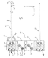
- the additional device 100 comprises a frame 110, which projects beyond the upper edge of the trough 2.
- an adapter bank 120 At the lower end of the frame 110 is an adapter bank 120, which is arranged in such a way is that this can be embedded in the tub 2.
- the control and / or operating unit 200 can be connected via a cable connection with a drive of the additional device.
- the cable is both a motor of the drive supplied with electricity, as well as driven, so that performs these movements.
- the control of the control and operating unit 200 by a user is made via the touch-sensitive display 210. It may be a capacitive or resistive touch-sensitive screen.
- a control board 230 having processors and memory units disposed thereon.
- the frame 110 comprises two grip parts 111 and 112 extending in the xz-plane, by means of which the auxiliary device 100 can be put out of and into the trough.
- the handles 111 and 112 are rails 113 and 114, which connect the two handles together.
- an adapter bank 120 is additionally arranged, which in the present exemplary embodiment comprises four adapters 121 to 124.
- the frame 110 may be made of metal or a plastic. It is also possible that, for example, the handles 111 and 112 made of metal and the rails 113 and 114 are made of a plastic. On the rails 113, 114 are also elevations 115 and 116, so that the frame is only pointwise in contact with the tub. The constant width of the frame is ensured by cross struts 117.
- the adapter bank 120 comprises a housing 130 which at the same time forms the housing for the four adapters 121 to 124.
- the housing is made of plastic and includes openings 125 which allow liquid in the tub to enter the interior of the housing 130.
- the adapter 121 comprises at least one movable relative to the housing Coupling element 140 or 142.
- the coupling elements may be made of plastic, stainless steel, titanium, other medical materials or other chemically resistant or water-resistant materials and are beyond the surface 131 of the housing 130 in the z direction out.
- the movable coupling elements 140 and 142 are spring-mounted in the z-direction.
- the coupling elements sit on one in the representation of the FIG. 2 unrecognizable shaft, which is driven by a mechanical, hydraulic or pneumatic.
- the shaft is anchored to a bottom of the housing and has a spring mechanism which allows suspension of the coupling element in the z-direction.
- the coupling element can be pressed in the negative z-direction at least by the height at which it projects beyond the surface 131. This makes it possible that the coupling element yields and the rotation of the coupling element progresses so far that a pin arranged on a medical instrument engages in the groove of the coupling element and thus a positive connection is generated, so that the movement of the coupling element in an active movement of the medical Instruments is implemented.
- the medical instruments are also fixed with a fixing device 150 at its proximal end in the adapter bank 120. This gives a precise alignment between the coupling elements and the mechanics of the medical instruments.
- a drive 160 is also arranged, which is arranged at the upper end in the region of the handle 112.
- This comprises a housing 161, in which there is an electric motor in this case.
- a coupling rod 162 On the electric motor is a coupling rod 162, which is guided through an opening in the adapter bank 120 and is coupled there via the mechanical, pneumatic or hydraulic transmission with the individual coupling elements.
- the housing 161 is connected in the present example via a strut 118 to the adapter bank.
- FIG. 3a is a plan view of the adapter bank of FIG. 1 and 2 shown in the xy plane.
- a fixation device 150 as well as two medical instruments 170 and 170 'can be seen, so that the interaction between the instrument 170 and the coupling elements can be explained in more detail.
- the instrument 170 comprises a shaft 172, which is rotatable along the axis of the shaft in the direction R.
- the shaft 172 also includes at its distal end a movable tip 173, which is rotatable in the yz plane in the direction B.
- the instrument comprises a housing (which is cut open in this plan view) which, inter alia, comprises four mechanisms 176, 178, 180 and 182.
- a rotation of the element 176 causes an opening in the direction 02
- the mechanism 178 a rotation in the direction 01
- the element 180 a rotation in the direction R
- the element 182 a rotation in the direction B.
- each comprises the adapter of the adapter bank 120 has two movable coupling elements 144 and 146, which in each case comprises two grooves 148 extending in a crosswise manner relative to each other.
- the grooves are selected such that a pin located on the underside of the mechanisms 176 to 182, not shown, can be held in a form-fitting manner in the grooves.
- a movement of the coupling element 144 for example, into a movement of the mechanism 182 and thus an active movement of the tip 173 in the direction B is implemented.
- the pins on the underside of the mechanism of the medical instrument first press against the region of the coupling element 144 or 146 which delimits the grooves.
- the coupling element is pressed in the z direction down.
- the pin of the mechanism now slides along the surface bounding the grooves 148 until it engages in one of the grooves.
- the pressure on the spring-mounted coupling element 144 is reduced and the coupling element is pressed in the positive z-direction upwards.
- the positive connection between the groove and the pin of the medical instrument is brought about.
- the movement of the distal part of the medical instrument may be such that the coupling element 144 is initially moved by a certain angle in the clockwise direction and then by the same angle in the counterclockwise direction.
- an active movement is transmitted to the medical instrument, so that the distal tip 173 can be bent over an angular range of for example 180 ° and the arms of the clamp can be moved over a range of likewise almost 180 °,
- the grooves 148 serve inter alia also the fixation of the medical instrument.
- holes or webs can take over the function of the grooves.
- the shape of the fixing element, which is arranged on the coupling element, thus essentially depends on the mechanics of the medical instruments. If the medical instruments have pins, grooves or holes are preferable. Have these holes or grooves, webs or pins are used on the movable coupling element.
- each adapter has additional fixing aids.
- a recess 152 is present, which is embedded in the surface 131. In this area are in the illustrated medical instrument electrical contacts, which protrude slightly above the bottom of the medical instrument. These can be aligned in the recess 152, so that the positioning of the medical instrument in the adapter is simplified.
- a web 154 is present, which also engages in a corresponding recess in the underside of the medical instrument.
- the fixing device 150 also has as in the FIG. 3b recognizable, a latching lug 158 which engages in a corresponding recess of the medical instrument.
- the fixing device 150 comprises an undercut 160, which closes in a form-fitting manner with a projection 184 of the medical instrument.
- the fixed in the adapter 121 medical instrument 170 is fixed in its orientation relative to the adapter 121. Only the coupling via the coupling element 144 or 146 and the corresponding mechanism 178 or 182 causes an active movement of the distal end of the medical instrument. Other parts or areas of the medical instrument are not moved by the coupling elements.
- the fixation device 150 also includes a handle 156, which, when pulled in the negative y-direction, releases the medical instrument 170.
- This condition can be recognized, for example, in the adapter 124.
- the fixing element 150 comprises a stop, so that this can only be pulled over the half of the length of the adapter, for example, and then remains in the adapter. Also in this position, a release of the medical instrument from the adapter is possible.
- Both the adapter housing 130 and the coupling element 144, 146 and the gear train, not shown, which sits in the housing 130 may be made of plastic or metal.
- the fixing device 150 may also be made of plastic or metal.
- a flushing device 240 which comprises hoses 242/244 for a suction flush and / or a pressure flush.
- the hoses or the flushing liquid located therein are sucked or pressed by means of a pump 246.
- the hoses 242 and 244 for example, with the in the FIG. 3a shown rinse adapter 190 (which is connected to the medical instrument 170), which connects the lumen of the shaft 172 with the hose.
- a program can be initiated via the touch-sensitive display, which allows a pressure or suction rinsing of the lumen of the shaft 172.
- the controller 230 is programmed so that the single pump 246 can pressurize all four instruments located in the adapter bank 120 with a suction or pressure purge.
- the suction or pressure channel by channel that is, one adapter after another, carried out so that it can be determined at least for the suction irrigation, whether the lumen of the shaft of the medical instrument is clogged or not.
- the switching between suction and pressure operation is by a suction and / Pressure switch 248 performed.
- the channel switching, ie the channel-wise admission takes place in a channel switch, not shown.
- the blockage can be determined via the flow passing through the pump or the pressure associated therewith. Part of this technology is also used in the Sonomic products.
- the control device 230 includes, as mentioned above, a processor and a memory unit.
- the memory unit stores various programs for moving the instruments. Thus, depending on the inserted instrument, a program can be selected which defines the corresponding angular range of rotation of the instrument and the coupling elements to be controlled. These programs are initialized via the processor and the processor takes control of the drive so that it initiates the movement of the coupling elements according to the program.
- connection 250 is also a connection 250 recognizable, via which a connection between the drive 160 of the additional device 100 can take place with the control and / or control unit 200.
- a connection can be a copper connection.
Landscapes
- Health & Medical Sciences (AREA)
- Surgery (AREA)
- Life Sciences & Earth Sciences (AREA)
- Heart & Thoracic Surgery (AREA)
- Pathology (AREA)
- Oral & Maxillofacial Surgery (AREA)
- Engineering & Computer Science (AREA)
- Biomedical Technology (AREA)
- Nuclear Medicine, Radiotherapy & Molecular Imaging (AREA)
- Medical Informatics (AREA)
- Molecular Biology (AREA)
- Animal Behavior & Ethology (AREA)
- General Health & Medical Sciences (AREA)
- Public Health (AREA)
- Veterinary Medicine (AREA)
- Surgical Instruments (AREA)
Priority Applications (2)
| Application Number | Priority Date | Filing Date | Title |
|---|---|---|---|
| EP13180744.8A EP2837352A1 (fr) | 2013-08-16 | 2013-08-16 | Dispositif supplémentaire pour appareils de nettoyage à ultrasons, dispositif de commande pour un appareil à ultrasons et procédé de déplacement actif d'au moins une zone d'un instrument médical |
| US14/459,148 US9974614B2 (en) | 2013-08-16 | 2014-08-13 | Drive and auxiliary device for ultrasound cleaning apparatus |
Applications Claiming Priority (1)
| Application Number | Priority Date | Filing Date | Title |
|---|---|---|---|
| EP13180744.8A EP2837352A1 (fr) | 2013-08-16 | 2013-08-16 | Dispositif supplémentaire pour appareils de nettoyage à ultrasons, dispositif de commande pour un appareil à ultrasons et procédé de déplacement actif d'au moins une zone d'un instrument médical |
Publications (1)
| Publication Number | Publication Date |
|---|---|
| EP2837352A1 true EP2837352A1 (fr) | 2015-02-18 |
Family
ID=49028903
Family Applications (1)
| Application Number | Title | Priority Date | Filing Date |
|---|---|---|---|
| EP13180744.8A Withdrawn EP2837352A1 (fr) | 2013-08-16 | 2013-08-16 | Dispositif supplémentaire pour appareils de nettoyage à ultrasons, dispositif de commande pour un appareil à ultrasons et procédé de déplacement actif d'au moins une zone d'un instrument médical |
Country Status (1)
| Country | Link |
|---|---|
| EP (1) | EP2837352A1 (fr) |
Cited By (2)
| Publication number | Priority date | Publication date | Assignee | Title |
|---|---|---|---|---|
| US10648730B1 (en) | 2017-05-08 | 2020-05-12 | Cenorin, Llc | Medical implement drying apparatus |
| EP3763316A1 (fr) * | 2019-07-09 | 2021-01-13 | Ethicon LLC | Adaptateur pour un système de nettoyage d'outil chirurgical robotique |
Citations (3)
| Publication number | Priority date | Publication date | Assignee | Title |
|---|---|---|---|---|
| DE10248460A1 (de) * | 2002-10-17 | 2004-04-29 | Vanguard Ag Medical Services For Europe | Einrichtung zur Reinigung innerer Hohlräume von chirurgischen Instrumenten |
| WO2012098732A1 (fr) * | 2011-01-18 | 2012-07-26 | シャープ株式会社 | Appareil de nettoyage et procédé de nettoyage |
| WO2012148266A1 (fr) * | 2011-04-29 | 2012-11-01 | P.M.T. Partners Medische Techniek B.V. | Dispositif d'actionnement destiné à actionner un instrument médical dans une machine de nettoyage et de désinfection |
-
2013
- 2013-08-16 EP EP13180744.8A patent/EP2837352A1/fr not_active Withdrawn
Patent Citations (3)
| Publication number | Priority date | Publication date | Assignee | Title |
|---|---|---|---|---|
| DE10248460A1 (de) * | 2002-10-17 | 2004-04-29 | Vanguard Ag Medical Services For Europe | Einrichtung zur Reinigung innerer Hohlräume von chirurgischen Instrumenten |
| WO2012098732A1 (fr) * | 2011-01-18 | 2012-07-26 | シャープ株式会社 | Appareil de nettoyage et procédé de nettoyage |
| WO2012148266A1 (fr) * | 2011-04-29 | 2012-11-01 | P.M.T. Partners Medische Techniek B.V. | Dispositif d'actionnement destiné à actionner un instrument médical dans une machine de nettoyage et de désinfection |
Cited By (6)
| Publication number | Priority date | Publication date | Assignee | Title |
|---|---|---|---|---|
| US10648730B1 (en) | 2017-05-08 | 2020-05-12 | Cenorin, Llc | Medical implement drying apparatus |
| US11054183B2 (en) | 2017-05-08 | 2021-07-06 | Cenorin, Llc | Medical implement drying apparatus |
| EP3763316A1 (fr) * | 2019-07-09 | 2021-01-13 | Ethicon LLC | Adaptateur pour un système de nettoyage d'outil chirurgical robotique |
| WO2021005506A1 (fr) * | 2019-07-09 | 2021-01-14 | Ethicon Llc | Adaptateur pour un système de nettoyage d'outil chirurgical robotique |
| CN114144141A (zh) * | 2019-07-09 | 2022-03-04 | 西拉格国际有限公司 | 用于机器人外科工具清洁系统的适配器 |
| US12133775B2 (en) | 2019-07-09 | 2024-11-05 | Cilag Gmbh International | Adapter for a robotic surgical tool cleaning system |
Similar Documents
| Publication | Publication Date | Title |
|---|---|---|
| EP2996585B1 (fr) | Instrument chirurgical | |
| DE102007008099A1 (de) | Schlauchanordnung für ein Endoskop | |
| EP4011268A1 (fr) | Endoscope hybride pourvu de tambour rotatif pour applications médicales stériles | |
| EP3167839B1 (fr) | Mécanisme de mouvement et système de nettoyage d'instruments médicaux | |
| WO2015039938A1 (fr) | Effecteur terminal destiné à un instrument chirurgical et instrument chirurgical muni d'un effecteur terminal | |
| EP0605763A1 (fr) | Poinçonneuse à tissu | |
| EP2837353B1 (fr) | Entraînement et dispositif supplémentaire pour appareils de nettoyage à ultrasons | |
| DE112006000776T5 (de) | Endoskop | |
| WO2019092109A1 (fr) | Système de lavage | |
| WO2017194562A1 (fr) | Dispositif de retenue pour un anneau de suture | |
| DE102006038255B4 (de) | Verfahren und Vorrichtung zum Behandeln von Behältern | |
| DE102005014529A1 (de) | Ultraschallendoskop | |
| DE102020211128A1 (de) | Endoskop mit einer funktion zur verhinderung einer kettenverklemmung | |
| DE112018003556T5 (de) | Mit einer irrigationsfunktion ausgestattete saugvorrichtung | |
| EP2837352A1 (fr) | Dispositif supplémentaire pour appareils de nettoyage à ultrasons, dispositif de commande pour un appareil à ultrasons et procédé de déplacement actif d'au moins une zone d'un instrument médical | |
| DE60131466T2 (de) | System für die ophthalmologische chirurgie | |
| WO2011120642A1 (fr) | Instrument chirurgical | |
| DE102013110215A1 (de) | Vorrichtung zum Positionieren eines Endeffektors eines chirurgischen Instruments, und chirurgisches Instrument mit einem integrierten Manipulator | |
| DE102016001271A1 (de) | Transporteur eines Resektoskopes | |
| EP2201886B1 (fr) | Porte-vaisselle doté d'une pièce de raccordement pour marchandise de nettoyage tubulaire | |
| EP1986558B1 (fr) | Manipulateur de sonde | |
| WO2005110198A1 (fr) | Dispositif pour modifier la direction d'action d'un instrument | |
| EP1925248B1 (fr) | Manche d'appareil | |
| DE102017109473B4 (de) | Aufbereitungsgerät für medizinische Instrumente, Instrumententräger, und Verfahren zum Aufbereiten eines medizinischen Instruments | |
| DE102013005874A1 (de) | Griffstück für ein chirurgisches lnstrument |
Legal Events
| Date | Code | Title | Description |
|---|---|---|---|
| 17P | Request for examination filed |
Effective date: 20130816 |
|
| AK | Designated contracting states |
Kind code of ref document: A1 Designated state(s): AL AT BE BG CH CY CZ DE DK EE ES FI FR GB GR HR HU IE IS IT LI LT LU LV MC MK MT NL NO PL PT RO RS SE SI SK SM TR |
|
| AX | Request for extension of the european patent |
Extension state: BA ME |
|
| PUAI | Public reference made under article 153(3) epc to a published international application that has entered the european phase |
Free format text: ORIGINAL CODE: 0009012 |
|
| R17P | Request for examination filed (corrected) |
Effective date: 20150818 |
|
| RBV | Designated contracting states (corrected) |
Designated state(s): AL AT BE BG CH CY CZ DE DK EE ES FI FR GB GR HR HU IE IS IT LI LT LU LV MC MK MT NL NO PL PT RO RS SE SI SK SM TR |
|
| 17Q | First examination report despatched |
Effective date: 20151207 |
|
| STAA | Information on the status of an ep patent application or granted ep patent |
Free format text: STATUS: THE APPLICATION IS DEEMED TO BE WITHDRAWN |
|
| 18D | Application deemed to be withdrawn |
Effective date: 20160618 |