EP2837455A1 - Scie à table - Google Patents
Scie à table Download PDFInfo
- Publication number
- EP2837455A1 EP2837455A1 EP20140178187 EP14178187A EP2837455A1 EP 2837455 A1 EP2837455 A1 EP 2837455A1 EP 20140178187 EP20140178187 EP 20140178187 EP 14178187 A EP14178187 A EP 14178187A EP 2837455 A1 EP2837455 A1 EP 2837455A1
- Authority
- EP
- European Patent Office
- Prior art keywords
- assembly
- fence
- saw
- sliding rail
- support plate
- Prior art date
- Legal status (The legal status is an assumption and is not a legal conclusion. Google has not performed a legal analysis and makes no representation as to the accuracy of the status listed.)
- Granted
Links
Images




Classifications
-
- B—PERFORMING OPERATIONS; TRANSPORTING
- B23—MACHINE TOOLS; METAL-WORKING NOT OTHERWISE PROVIDED FOR
- B23D—PLANING; SLOTTING; SHEARING; BROACHING; SAWING; FILING; SCRAPING; LIKE OPERATIONS FOR WORKING METAL BY REMOVING MATERIAL, NOT OTHERWISE PROVIDED FOR
- B23D45/00—Sawing machines or sawing devices with circular saw blades or with friction saw discs
- B23D45/06—Sawing machines or sawing devices with circular saw blades or with friction saw discs with a circular saw blade arranged underneath a stationary work-table
-
- B—PERFORMING OPERATIONS; TRANSPORTING
- B23—MACHINE TOOLS; METAL-WORKING NOT OTHERWISE PROVIDED FOR
- B23D—PLANING; SLOTTING; SHEARING; BROACHING; SAWING; FILING; SCRAPING; LIKE OPERATIONS FOR WORKING METAL BY REMOVING MATERIAL, NOT OTHERWISE PROVIDED FOR
- B23D47/00—Sawing machines or sawing devices working with circular saw blades, characterised only by constructional features of particular parts
- B23D47/02—Sawing machines or sawing devices working with circular saw blades, characterised only by constructional features of particular parts of frames; of guiding arrangements for work-table or saw-carrier
- B23D47/025—Sawing machines or sawing devices working with circular saw blades, characterised only by constructional features of particular parts of frames; of guiding arrangements for work-table or saw-carrier of tables
-
- B—PERFORMING OPERATIONS; TRANSPORTING
- B23—MACHINE TOOLS; METAL-WORKING NOT OTHERWISE PROVIDED FOR
- B23Q—DETAILS, COMPONENTS, OR ACCESSORIES FOR MACHINE TOOLS, e.g. ARRANGEMENTS FOR COPYING OR CONTROLLING; MACHINE TOOLS IN GENERAL CHARACTERISED BY THE CONSTRUCTION OF PARTICULAR DETAILS OR COMPONENTS; COMBINATIONS OR ASSOCIATIONS OF METAL-WORKING MACHINES, NOT DIRECTED TO A PARTICULAR RESULT
- B23Q3/00—Devices holding, supporting, or positioning work or tools, of a kind normally removable from the machine
- B23Q3/005—Guides for workpieces
-
- B—PERFORMING OPERATIONS; TRANSPORTING
- B27—WORKING OR PRESERVING WOOD OR SIMILAR MATERIAL; NAILING OR STAPLING MACHINES IN GENERAL
- B27B—SAWS FOR WOOD OR SIMILAR MATERIAL; COMPONENTS OR ACCESSORIES THEREFOR
- B27B27/00—Guide fences or stops for timber in saw mills or sawing machines; Measuring equipment thereon
- B27B27/10—Devices for moving or adjusting the guide fences or stops
-
- Y—GENERAL TAGGING OF NEW TECHNOLOGICAL DEVELOPMENTS; GENERAL TAGGING OF CROSS-SECTIONAL TECHNOLOGIES SPANNING OVER SEVERAL SECTIONS OF THE IPC; TECHNICAL SUBJECTS COVERED BY FORMER USPC CROSS-REFERENCE ART COLLECTIONS [XRACs] AND DIGESTS
- Y10—TECHNICAL SUBJECTS COVERED BY FORMER USPC
- Y10T—TECHNICAL SUBJECTS COVERED BY FORMER US CLASSIFICATION
- Y10T83/00—Cutting
- Y10T83/748—With work immobilizer
- Y10T83/7593—Work-stop abutment
- Y10T83/7647—Adjustable
-
- Y—GENERAL TAGGING OF NEW TECHNOLOGICAL DEVELOPMENTS; GENERAL TAGGING OF CROSS-SECTIONAL TECHNOLOGIES SPANNING OVER SEVERAL SECTIONS OF THE IPC; TECHNICAL SUBJECTS COVERED BY FORMER USPC CROSS-REFERENCE ART COLLECTIONS [XRACs] AND DIGESTS
- Y10—TECHNICAL SUBJECTS COVERED BY FORMER USPC
- Y10T—TECHNICAL SUBJECTS COVERED BY FORMER US CLASSIFICATION
- Y10T83/00—Cutting
- Y10T83/768—Rotatable disc tool pair or tool and carrier
- Y10T83/7684—With means to support work relative to tool[s]
Definitions
- This invention relates generally to a table saw and more specifically to construction techniques for manufacturing table saws.
- Typical portable table saws have a table, a base supporting the table, a saw assembly attached to the table and/or the base.
- the base is typically made of metal or plastic.
- Bases made of metal are typically heavy and relatively flexible, as they consist mostly of metal paneling. Bases made of plastic on the other hand could break when the table saw is dropped.
- an improved table saw is employed.
- the table saw has a base assembly, a table assembly supported by the base assembly, a saw assembly supported by at least one of the table assembly and the base assembly, the saw assembly including a saw blade extending through the table assembly, wherein the base assembly comprises at least one foot having a substantially horizontal surface, a substantially vertical surface, and a curved surface disposed between the substantially horizontal surface and the substantially vertical surface, wherein the substantially vertical surface is substantially coplanar with a surface of the table assembly so that the table saw can be disposed on the substantially vertical surface and the surface of the table assembly.
- a table saw 100 may include a base assembly 10, a table assembly 11 supported by base assembly 10, and a saw assembly (not shown) supported by the table assembly 11.
- a saw assembly (not shown) supported by the table assembly 11.
- Persons skilled in the art will recognize that the construction of the saw assembly is well known and can be found in US Patent Nos. 5,875,698 , 6,009,782 , 6,450,077 and 6,907,807 , all of which are hereby incorporated by reference.
- the saw assembly may include a blade 31, extending through table assembly 11.
- a blade guard 31 G may surround a portion of blade 31.
- Base assembly 11 may include at least one tube 21 attached to table assembly 10.
- Tube 21 may be made of a composite material, such as carbon fiber or fiber glass, extruded metal, such as aluminum, steel tubing or molded plastic. Persons skilled in the art will recognize plastic tubing may be molded via gas-assist, injection molded, etc. Persons skilled in the art are referred to US Patent Publication No. 2007/0245869 , which is hereby incorporated by reference for further details on such arrangement.
- base assembly 10 has two substantially U-shaped tubes 21 connected to table assembly 11.
- Each U-shaped tube 21 preferably has two substantially vertical tubes 21V and a substantially horizontal tube 21 H.
- Tubes 21 V, 21 H may be welded to each other or formed integrally.
- Tubes 21 may be bolted directly unto table assembly 11 as disclosed in US Patent Publication No. 2007/0245869 .
- a carrying handle 21C may be attached to tubes 21 V or table assembly 11.
- carrying handle 21C is a tube welded to tubes 21V and having a grip portion, preferably made of rubber.
- Tubes 21 may have adjustable feet assemblies 23.
- foot assembly 23 is preferably made of plastic with overmolded rubber, or another high friction material.
- foot assembly 23 is made of two halves sandwiching tubes 21 V, 21 H.
- Bolts 23BB may extend bosses 23B in both halves of foot assembly 23, and through tubes 21 V, 21 H to fix tubes 21 V, 21 H to foot assembly 23.
- Each foot assembly 23 preferably has a substantially horizontal bottom surface 23H, a substantially vertical outer surface 23V and a curved surface 23C disposed between surfaces 23H, 23V.
- curved surface 23C is preferably connected to surfaces 23H, 23V.
- Bottom surfaces 23H preferably define a substantially horizontal plane HP. It is desirable that the center of gravity CG is disposed between the foot assemblies 23.
- Table assembly 11 has a horizontal surface 11 H for supporting a workpiece (not shown) and an outer surface 11S adjacent to horizontal surface 11 H.
- outer surface 11S is the outermost sideward surface on table assembly 11 and that nothing in table assembly 11 will extend beyond outer surface 11S.
- outer surface 11S and vertical surface 23V define a substantially vertical plane VP, which may be substantially perpendicular to horizontal plane HP.
- Center of gravity CG is preferably disposed between feet assemblies 23 and table assembly 11 and/or outer surface 11S. This would allow a user to stably dispose table saw 100 on its side, so that outer surface 11S and table assembly 11 and/or feet assemblies 23 are resting on the floor or other substantially horizontal surface.
- the center of gravity CG is disposed between feet assemblies 23 and handle 21C so that when a user is holding table saw 100 by handle 21C with the table assembly 11 facing the user (as shown in FIG. 3 ), the center of gravity CG causes table saw 100 to move towards the user along the direction of arrow B.
- feet assemblies 23 will provide better impact protection against drops if table saw 100 is dropped.
- having feet assemblies 23 with curved surfaces 23C could allow a user to rotate table saw 100 from a horizontal position (as shown on the left side of FIG. 1 ) to a vertical position (as shown on the right side of FIG. 1 ).
- the user for example could grab handle 21C or table assembly 11 on the left side and lift table saw 100 while maintaining feet assemblies 23 at the right end of table saw 100 on the floor or support surface.
- the table saw 100 would then end up in the vertical position of FIG. 1 , with an exposed handle 21C.
- front panel 22 may be disposed on tube(s) 21.
- Front panel 22 may be made of metal or plastic.
- Front panel 22 may support an on/off switch 32, a height adjustment crank 33 and a bevel lock crank 34.
- table saw 100 preferably has a front rail assembly 50 attached to a front side of table assembly 11, a rear rail assembly 50 attached to a rear side of table assembly 11, the rail assemblies 50 supporting a fence assembly 60.
- a front rail assembly 50 attached to a front side of table assembly 11
- a rear rail assembly 50 attached to a rear side of table assembly 11, the rail assemblies 50 supporting a fence assembly 60.
- Persons skilled in the art are referred to US Patent Nos. 5,722,308 and 6,450,077 , which are fully incorporated by reference, for information on the construction of rail assembly 50 and fence assembly 60.
- Each rail assembly 50 preferably includes a fixed rail assembly 51 bolted unto table assembly 11 via a bolt 51 B.
- Rail assembly 51 may include a fixed rail 51 R, which is preferably made of extruded aluminum. Fixed rail 51 R may have an overmolded portion 510.
- a sliding rail 52 may be slidingly disposed on each fixed rail assembly 51.
- Sliding rail 52 is preferably made of extruded aluminum.
- Sliding rail 52 preferably has a slot 52S and a channel 52C disposed adjacent to the slot 52S.
- Each sliding rail 52 may have a rack 53.
- a boss 54 may extend through slot 52S and threadingly engage a nut 54N disposed in channel 52C. This allows a user to move boss 54 along slot 52S.
- fence assembly 60 has a fence beam 62 with a fence plane FP against which a user would place a workpiece, and a mount 61 supporting the fence beam 62. Mount 61 is disposed on boss 54. By adjusting the position of boss 54 relative to slot 52S, the user can thus adjust the position of the fence assembly 60 relative to the sliding rail 52 and/or adjust the parallelism of fence assembly 60 relative to blade 31.
- mount 61 preferably has a body 61 B that is disposed on sliding rail 52, a post 61 P connected to body 61 B, and a fence support 61 F connected to the post 61 P for supporting a fence beam 62.
- body 61 B has a horizontal surface 61BS that contacts the upper surface of sliding rail 52, and a slot 61 S for receiving boss 54.
- body 61 B carries a lock 61 L rotatably attached to body 61 B.
- Lock 61 L preferably has a cam surface 61 LC extending radially from the axis of rotation of lock 61 L.
- One possible means for attachment is to provide body 61 B with ears 61IE.
- Lock 61 L can then be disposed between ears 61IE.
- a pin 61 LP can then extend through ears 61IE and lock 61 L to maintain the rotational connection between lock 61 L and ears 61IE.
- body 61 B is made of plastic and carries an insert 61I made of metal, such as steel. Having such insert strengthens body 61 B while reducing overall weight. Insert 61I may have slot 61 S and/or ears 61IE.
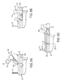
- the user can move fence assembly 60 so that slot 61 S can receive boss 54 (see FIG. 6A ).
- boss 54 is in slot 61 S
- the user can rotate fence assembly 60 so that mount 61 (and horizontal surface 61 BS) is on sliding rail 52.
- the user can then rotate lock 61 L so that cam surface 61 LC extends into slot 52S and contacts a wall of sliding rail 52, preferably a wall defining slot 52S.
- FIGS. 6B-6C illustrate the first and second positions, respectively. In the first position, mount 61 is connected to the boss 54 closest to blade 31. In such position, fence plane FP is within the ends of fixed rail assembly 51, sliding rail 52 and/or table 11.
- mount 61 In the second position, mount 61 is connected to the boss 54 farthest from blade 31. In such position, fence plane FP is preferably outside of the ends of fixed rail assembly 51, sliding rail 52 and/or table 11. Persons skilled in the art will recognize that this second position is achievable because mount 61 is effectively cantilevered by the connection to boss 54 and horizontal surface 61BS.
- fence assembly 60 may include a support member 65 rotatably mounted to fence support 61 F.
- Support member 65 may include an arm 65A pivotally connected to fence support 61 F and a support plate 65P for supporting a workpiece W.
- Arm 65A preferably has a slot 65AS.
- Fence support 61 F has a retaining fastener 61 FR extending through slot 65AS, capturing arm 65A.
- support plate 65P can be moved along slot 65AS to be moved between several positions.
- support plate 65P can support a worpiece W when the fence assembly 60 is moved beyond table assembly 11 (as shown in FIG. 8A ).
- support plate 65P is preferably substantially coplanar with surface 11 H of table assembly 11.
- arm 65A (and thus support plate 65P) can be moved upwardly. This allows support plate 65SP to be placed on table assembly 11, as shown in FIG. 8B .
- fence support 61 F Preferably fence support 61 F, have slots 61 FS that can receive a pin 65AP extending from arm 65A towards fence support 61 F.
- Such pin/slot combination will allow the user to easily find the different positions of arm 65A (and thus support plate 65P).
- arm 65A can be rotated about retaining fastener 61 FR to a third position (shown in solid lines in FIG. 1 and broken lines in FIG. 8B ) where support plate 65SP is behind fence plane FP, and thus does not interfere with a cutting operation.
- fence support 61 F will have a storage slot 61 FSS that receives pin 65AP when arm 65A is rotated towards the third position.
- a spring 61 FPS may be disposed within storage slot 61 FSS for capturing and retaining pin 65AP (and thus arm 65A).
Landscapes
- Engineering & Computer Science (AREA)
- Mechanical Engineering (AREA)
- Life Sciences & Earth Sciences (AREA)
- Wood Science & Technology (AREA)
- Forests & Forestry (AREA)
- Sawing (AREA)
Applications Claiming Priority (2)
| Application Number | Priority Date | Filing Date | Title |
|---|---|---|---|
| US201361865763P | 2013-08-14 | 2013-08-14 | |
| US14/319,386 US9731362B2 (en) | 2013-08-14 | 2014-06-30 | Table saw |
Publications (2)
| Publication Number | Publication Date |
|---|---|
| EP2837455A1 true EP2837455A1 (fr) | 2015-02-18 |
| EP2837455B1 EP2837455B1 (fr) | 2020-04-22 |
Family
ID=51212753
Family Applications (1)
| Application Number | Title | Priority Date | Filing Date |
|---|---|---|---|
| EP14178187.2A Active EP2837455B1 (fr) | 2013-08-14 | 2014-07-23 | Scie à table |
Country Status (3)
| Country | Link |
|---|---|
| US (4) | US9731362B2 (fr) |
| EP (1) | EP2837455B1 (fr) |
| CN (1) | CN204135460U (fr) |
Cited By (1)
| Publication number | Priority date | Publication date | Assignee | Title |
|---|---|---|---|---|
| EP4230333A1 (fr) * | 2022-02-03 | 2023-08-23 | Festool GmbH | Dispositif de sciage, ensemble d'empilement, ensemble couvercle, ensemble de transport et procédé |
Families Citing this family (8)
| Publication number | Priority date | Publication date | Assignee | Title |
|---|---|---|---|---|
| US8584564B2 (en) * | 2006-04-21 | 2013-11-19 | Black & Decker Inc. | Table saw |
| DE102013220233A1 (de) * | 2013-10-08 | 2015-04-09 | Robert Bosch Gmbh | Werkzeugmaschinensystem |
| US9962852B2 (en) * | 2014-08-29 | 2018-05-08 | Black & Decker Inc. | Miter saw with improved carrying mode |
| CN207189852U (zh) | 2017-06-05 | 2018-04-06 | 米沃奇电动工具公司 | 台锯 |
| US10695849B2 (en) | 2018-02-19 | 2020-06-30 | Robert Bosch Gmbh | Table saw with two stage table extension system |
| US10717205B1 (en) * | 2019-03-11 | 2020-07-21 | Chin-Chin Chang | Slide mechanism and rip fence of table saw |
| US10759083B1 (en) * | 2019-04-30 | 2020-09-01 | Chin-Chin Chang | Mechanism for pivoting a limit plate to top of a rip fence |
| TWI737433B (zh) * | 2020-08-05 | 2021-08-21 | 墩豐機械工業股份有限公司 | 具有擋料板快速鎖固裝置之檯鋸機 |
Citations (8)
| Publication number | Priority date | Publication date | Assignee | Title |
|---|---|---|---|---|
| US5722308A (en) | 1995-10-10 | 1998-03-03 | Black & Decker Inc. | Movable fence for a machine tool |
| US5845555A (en) * | 1994-11-21 | 1998-12-08 | Dawley; James Alonzo | Multi-position adjustable work stop assembly |
| US5875698A (en) | 1996-06-17 | 1999-03-02 | Black & Decker Inc. | Blade and motor carrier with height/angle adjustment mechanism |
| US6009782A (en) | 1997-06-19 | 2000-01-04 | Makita Corporation | Table saw |
| US6907807B2 (en) | 1999-06-10 | 2005-06-21 | Black & Decker Inc. | Table saw |
| US20070245869A1 (en) | 2006-04-21 | 2007-10-25 | Welsh Robert P | Table saw |
| US20110197733A1 (en) * | 2010-02-12 | 2011-08-18 | Durq Machinery Corp. | Rip fence mechanism for sawing machine |
| WO2012009203A1 (fr) * | 2010-07-12 | 2012-01-19 | Robert Bosch Gmbh | Scie sur table portable |
Family Cites Families (13)
| Publication number | Priority date | Publication date | Assignee | Title |
|---|---|---|---|---|
| US5115847A (en) * | 1991-04-19 | 1992-05-26 | Taber Tarrell L | Adjustable support apparatus for table saws |
| US5619896A (en) * | 1995-06-27 | 1997-04-15 | Chen; Ruey Z. | Base of a sawing machine |
| CA2234576C (fr) * | 1997-05-09 | 2002-07-09 | James Hilliard | Scie circulaire a table |
| US6986370B1 (en) * | 2000-02-01 | 2006-01-17 | Home Depot U.S.A., Inc. | Table saw |
| US6644157B2 (en) * | 2001-10-11 | 2003-11-11 | Durq Machinery Corp. | Table saw having adjustable worktable |
| TWM251667U (en) * | 2004-03-22 | 2004-12-01 | Durq Machinery Corp | Table saw |
| US7156008B2 (en) * | 2004-05-28 | 2007-01-02 | Robert Bosch Gmbh | Flip-up multi-mode workpiece stop for miter saw |
| EP2075078B1 (fr) * | 2007-12-29 | 2014-07-16 | Positec Power Tools (Suzhou) Co., Ltd. | Scie à table |
| USD626158S1 (en) * | 2009-01-28 | 2010-10-26 | David Jebb | Table saw |
| US8424434B2 (en) * | 2009-04-28 | 2013-04-23 | Robert Bosch Gmbh | Universal fence for a power table saw |
| TW201201937A (en) * | 2010-07-07 | 2012-01-16 | Durq Machinery Corp | Material blocking device for table sawing machine |
| US9527144B2 (en) * | 2011-11-28 | 2016-12-27 | Robert Bosch Tool Corporation | Extendable workpiece support for a portable power tool |
| CN106475978B (zh) * | 2015-09-02 | 2019-03-08 | 南京德朔实业有限公司 | 一种工作台和靠栅装置的组合以及具有该组合的台型工具 |
-
2014
- 2014-06-30 US US14/319,386 patent/US9731362B2/en active Active
- 2014-07-23 EP EP14178187.2A patent/EP2837455B1/fr active Active
- 2014-08-14 CN CN201420457736.7U patent/CN204135460U/zh not_active Expired - Fee Related
-
2017
- 2017-07-13 US US15/648,961 patent/US10500655B2/en active Active
-
2019
- 2019-11-04 US US16/673,285 patent/US11077505B2/en active Active
-
2021
- 2021-06-29 US US17/362,210 patent/US11590592B2/en active Active
Patent Citations (9)
| Publication number | Priority date | Publication date | Assignee | Title |
|---|---|---|---|---|
| US5845555A (en) * | 1994-11-21 | 1998-12-08 | Dawley; James Alonzo | Multi-position adjustable work stop assembly |
| US5722308A (en) | 1995-10-10 | 1998-03-03 | Black & Decker Inc. | Movable fence for a machine tool |
| US6450077B1 (en) | 1995-10-10 | 2002-09-17 | Black & Decker Inc. | Movable fence for a machine tool |
| US5875698A (en) | 1996-06-17 | 1999-03-02 | Black & Decker Inc. | Blade and motor carrier with height/angle adjustment mechanism |
| US6009782A (en) | 1997-06-19 | 2000-01-04 | Makita Corporation | Table saw |
| US6907807B2 (en) | 1999-06-10 | 2005-06-21 | Black & Decker Inc. | Table saw |
| US20070245869A1 (en) | 2006-04-21 | 2007-10-25 | Welsh Robert P | Table saw |
| US20110197733A1 (en) * | 2010-02-12 | 2011-08-18 | Durq Machinery Corp. | Rip fence mechanism for sawing machine |
| WO2012009203A1 (fr) * | 2010-07-12 | 2012-01-19 | Robert Bosch Gmbh | Scie sur table portable |
Cited By (1)
| Publication number | Priority date | Publication date | Assignee | Title |
|---|---|---|---|---|
| EP4230333A1 (fr) * | 2022-02-03 | 2023-08-23 | Festool GmbH | Dispositif de sciage, ensemble d'empilement, ensemble couvercle, ensemble de transport et procédé |
Also Published As
| Publication number | Publication date |
|---|---|
| CN204135460U (zh) | 2015-02-04 |
| US10500655B2 (en) | 2019-12-10 |
| US20150107429A1 (en) | 2015-04-23 |
| US9731362B2 (en) | 2017-08-15 |
| US20200406381A1 (en) | 2020-12-31 |
| US20170341164A1 (en) | 2017-11-30 |
| EP2837455B1 (fr) | 2020-04-22 |
| US20210387271A1 (en) | 2021-12-16 |
| US11590592B2 (en) | 2023-02-28 |
| US11077505B2 (en) | 2021-08-03 |
Similar Documents
| Publication | Publication Date | Title |
|---|---|---|
| US11077505B2 (en) | Table saw | |
| US12168258B2 (en) | Table saw | |
| US8272304B2 (en) | Miter saw with improved dust collection system | |
| EP2156930B1 (fr) | Scie à onglets ayant une butée qui est ajustée automatiquement | |
| EP2593279B1 (fr) | Scie à table portable | |
| US20120167738A1 (en) | Miter saw with adjustable fence | |
| US8127648B2 (en) | Table saw guard system | |
| US20080022825A1 (en) | Miter Saw With Top Table | |
| US9849605B2 (en) | Power miter saw having a fence with elevated platforms | |
| CN1974094A (zh) | 用于电锯的组合式防护系统和装置 | |
| US20100005937A1 (en) | Guard Assembly for Table Saw | |
| CN101875138B (zh) | 具有对称护板存储能力的台锯 | |
| US20080022824A1 (en) | Fence mounting structure for circular saw | |
| EP3170634B1 (fr) | Scie à onglets | |
| EP2017025A1 (fr) | Couteau diviseur pour scie circulaire à table | |
| EP3165313B1 (fr) | Scie à onglets avec tiges | |
| EP3165312B1 (fr) | Scie à onglets avec tige glissière | |
| CN201755697U (zh) | 切割机 | |
| CN112518022A (zh) | 具有改进刚性架结构的切割单元及切割机 | |
| US20170129025A1 (en) | Saw | |
| CN102380794A (zh) | 切割机的附件 | |
| CN102310231A (zh) | 切割机 |
Legal Events
| Date | Code | Title | Description |
|---|---|---|---|
| 17P | Request for examination filed |
Effective date: 20140723 |
|
| AK | Designated contracting states |
Kind code of ref document: A1 Designated state(s): AL AT BE BG CH CY CZ DE DK EE ES FI FR GB GR HR HU IE IS IT LI LT LU LV MC MK MT NL NO PL PT RO RS SE SI SK SM TR |
|
| AX | Request for extension of the european patent |
Extension state: BA ME |
|
| PUAI | Public reference made under article 153(3) epc to a published international application that has entered the european phase |
Free format text: ORIGINAL CODE: 0009012 |
|
| R17P | Request for examination filed (corrected) |
Effective date: 20150811 |
|
| RBV | Designated contracting states (corrected) |
Designated state(s): AL AT BE BG CH CY CZ DE DK EE ES FI FR GB GR HR HU IE IS IT LI LT LU LV MC MK MT NL NO PL PT RO RS SE SI SK SM TR |
|
| GRAP | Despatch of communication of intention to grant a patent |
Free format text: ORIGINAL CODE: EPIDOSNIGR1 |
|
| STAA | Information on the status of an ep patent application or granted ep patent |
Free format text: STATUS: GRANT OF PATENT IS INTENDED |
|
| INTG | Intention to grant announced |
Effective date: 20191204 |
|
| RIN1 | Information on inventor provided before grant (corrected) |
Inventor name: ELDER, CHRISTIAN V. Inventor name: MORELAND, FLOYD E. Inventor name: BILLINGS, ROSS Inventor name: CHAIKOWSKY, PETER Inventor name: SCHROEDER, JAMES D Inventor name: LEASURE, JEREMY D Inventor name: CEROLL, WARREN |
|
| GRAS | Grant fee paid |
Free format text: ORIGINAL CODE: EPIDOSNIGR3 |
|
| GRAA | (expected) grant |
Free format text: ORIGINAL CODE: 0009210 |
|
| STAA | Information on the status of an ep patent application or granted ep patent |
Free format text: STATUS: THE PATENT HAS BEEN GRANTED |
|
| AK | Designated contracting states |
Kind code of ref document: B1 Designated state(s): AL AT BE BG CH CY CZ DE DK EE ES FI FR GB GR HR HU IE IS IT LI LT LU LV MC MK MT NL NO PL PT RO RS SE SI SK SM TR |
|
| REG | Reference to a national code |
Ref country code: GB Ref legal event code: FG4D |
|
| REG | Reference to a national code |
Ref country code: CH Ref legal event code: EP |
|
| REG | Reference to a national code |
Ref country code: DE Ref legal event code: R096 Ref document number: 602014064031 Country of ref document: DE |
|
| REG | Reference to a national code |
Ref country code: IE Ref legal event code: FG4D |
|
| REG | Reference to a national code |
Ref country code: AT Ref legal event code: REF Ref document number: 1259423 Country of ref document: AT Kind code of ref document: T Effective date: 20200515 |
|
| REG | Reference to a national code |
Ref country code: LT Ref legal event code: MG4D |
|
| REG | Reference to a national code |
Ref country code: NL Ref legal event code: MP Effective date: 20200422 |
|
| PG25 | Lapsed in a contracting state [announced via postgrant information from national office to epo] |
Ref country code: GR Free format text: LAPSE BECAUSE OF FAILURE TO SUBMIT A TRANSLATION OF THE DESCRIPTION OR TO PAY THE FEE WITHIN THE PRESCRIBED TIME-LIMIT Effective date: 20200723 Ref country code: NO Free format text: LAPSE BECAUSE OF FAILURE TO SUBMIT A TRANSLATION OF THE DESCRIPTION OR TO PAY THE FEE WITHIN THE PRESCRIBED TIME-LIMIT Effective date: 20200722 Ref country code: IS Free format text: LAPSE BECAUSE OF FAILURE TO SUBMIT A TRANSLATION OF THE DESCRIPTION OR TO PAY THE FEE WITHIN THE PRESCRIBED TIME-LIMIT Effective date: 20200822 Ref country code: NL Free format text: LAPSE BECAUSE OF FAILURE TO SUBMIT A TRANSLATION OF THE DESCRIPTION OR TO PAY THE FEE WITHIN THE PRESCRIBED TIME-LIMIT Effective date: 20200422 Ref country code: SE Free format text: LAPSE BECAUSE OF FAILURE TO SUBMIT A TRANSLATION OF THE DESCRIPTION OR TO PAY THE FEE WITHIN THE PRESCRIBED TIME-LIMIT Effective date: 20200422 Ref country code: PT Free format text: LAPSE BECAUSE OF FAILURE TO SUBMIT A TRANSLATION OF THE DESCRIPTION OR TO PAY THE FEE WITHIN THE PRESCRIBED TIME-LIMIT Effective date: 20200824 Ref country code: LT Free format text: LAPSE BECAUSE OF FAILURE TO SUBMIT A TRANSLATION OF THE DESCRIPTION OR TO PAY THE FEE WITHIN THE PRESCRIBED TIME-LIMIT Effective date: 20200422 Ref country code: FI Free format text: LAPSE BECAUSE OF FAILURE TO SUBMIT A TRANSLATION OF THE DESCRIPTION OR TO PAY THE FEE WITHIN THE PRESCRIBED TIME-LIMIT Effective date: 20200422 |
|
| REG | Reference to a national code |
Ref country code: AT Ref legal event code: MK05 Ref document number: 1259423 Country of ref document: AT Kind code of ref document: T Effective date: 20200422 |
|
| PG25 | Lapsed in a contracting state [announced via postgrant information from national office to epo] |
Ref country code: LV Free format text: LAPSE BECAUSE OF FAILURE TO SUBMIT A TRANSLATION OF THE DESCRIPTION OR TO PAY THE FEE WITHIN THE PRESCRIBED TIME-LIMIT Effective date: 20200422 Ref country code: HR Free format text: LAPSE BECAUSE OF FAILURE TO SUBMIT A TRANSLATION OF THE DESCRIPTION OR TO PAY THE FEE WITHIN THE PRESCRIBED TIME-LIMIT Effective date: 20200422 Ref country code: RS Free format text: LAPSE BECAUSE OF FAILURE TO SUBMIT A TRANSLATION OF THE DESCRIPTION OR TO PAY THE FEE WITHIN THE PRESCRIBED TIME-LIMIT Effective date: 20200422 Ref country code: BG Free format text: LAPSE BECAUSE OF FAILURE TO SUBMIT A TRANSLATION OF THE DESCRIPTION OR TO PAY THE FEE WITHIN THE PRESCRIBED TIME-LIMIT Effective date: 20200722 |
|
| PG25 | Lapsed in a contracting state [announced via postgrant information from national office to epo] |
Ref country code: AL Free format text: LAPSE BECAUSE OF FAILURE TO SUBMIT A TRANSLATION OF THE DESCRIPTION OR TO PAY THE FEE WITHIN THE PRESCRIBED TIME-LIMIT Effective date: 20200422 |
|
| REG | Reference to a national code |
Ref country code: DE Ref legal event code: R097 Ref document number: 602014064031 Country of ref document: DE |
|
| PG25 | Lapsed in a contracting state [announced via postgrant information from national office to epo] |
Ref country code: IT Free format text: LAPSE BECAUSE OF FAILURE TO SUBMIT A TRANSLATION OF THE DESCRIPTION OR TO PAY THE FEE WITHIN THE PRESCRIBED TIME-LIMIT Effective date: 20200422 Ref country code: RO Free format text: LAPSE BECAUSE OF FAILURE TO SUBMIT A TRANSLATION OF THE DESCRIPTION OR TO PAY THE FEE WITHIN THE PRESCRIBED TIME-LIMIT Effective date: 20200422 Ref country code: CZ Free format text: LAPSE BECAUSE OF FAILURE TO SUBMIT A TRANSLATION OF THE DESCRIPTION OR TO PAY THE FEE WITHIN THE PRESCRIBED TIME-LIMIT Effective date: 20200422 Ref country code: SM Free format text: LAPSE BECAUSE OF FAILURE TO SUBMIT A TRANSLATION OF THE DESCRIPTION OR TO PAY THE FEE WITHIN THE PRESCRIBED TIME-LIMIT Effective date: 20200422 Ref country code: EE Free format text: LAPSE BECAUSE OF FAILURE TO SUBMIT A TRANSLATION OF THE DESCRIPTION OR TO PAY THE FEE WITHIN THE PRESCRIBED TIME-LIMIT Effective date: 20200422 Ref country code: DK Free format text: LAPSE BECAUSE OF FAILURE TO SUBMIT A TRANSLATION OF THE DESCRIPTION OR TO PAY THE FEE WITHIN THE PRESCRIBED TIME-LIMIT Effective date: 20200422 Ref country code: AT Free format text: LAPSE BECAUSE OF FAILURE TO SUBMIT A TRANSLATION OF THE DESCRIPTION OR TO PAY THE FEE WITHIN THE PRESCRIBED TIME-LIMIT Effective date: 20200422 Ref country code: ES Free format text: LAPSE BECAUSE OF FAILURE TO SUBMIT A TRANSLATION OF THE DESCRIPTION OR TO PAY THE FEE WITHIN THE PRESCRIBED TIME-LIMIT Effective date: 20200422 |
|
| PG25 | Lapsed in a contracting state [announced via postgrant information from national office to epo] |
Ref country code: PL Free format text: LAPSE BECAUSE OF FAILURE TO SUBMIT A TRANSLATION OF THE DESCRIPTION OR TO PAY THE FEE WITHIN THE PRESCRIBED TIME-LIMIT Effective date: 20200422 Ref country code: SK Free format text: LAPSE BECAUSE OF FAILURE TO SUBMIT A TRANSLATION OF THE DESCRIPTION OR TO PAY THE FEE WITHIN THE PRESCRIBED TIME-LIMIT Effective date: 20200422 Ref country code: MC Free format text: LAPSE BECAUSE OF FAILURE TO SUBMIT A TRANSLATION OF THE DESCRIPTION OR TO PAY THE FEE WITHIN THE PRESCRIBED TIME-LIMIT Effective date: 20200422 |
|
| PLBE | No opposition filed within time limit |
Free format text: ORIGINAL CODE: 0009261 |
|
| REG | Reference to a national code |
Ref country code: CH Ref legal event code: PL |
|
| STAA | Information on the status of an ep patent application or granted ep patent |
Free format text: STATUS: NO OPPOSITION FILED WITHIN TIME LIMIT |
|
| 26N | No opposition filed |
Effective date: 20210125 |
|
| REG | Reference to a national code |
Ref country code: BE Ref legal event code: MM Effective date: 20200731 |
|
| PG25 | Lapsed in a contracting state [announced via postgrant information from national office to epo] |
Ref country code: LU Free format text: LAPSE BECAUSE OF NON-PAYMENT OF DUE FEES Effective date: 20200723 Ref country code: FR Free format text: LAPSE BECAUSE OF NON-PAYMENT OF DUE FEES Effective date: 20200731 Ref country code: CH Free format text: LAPSE BECAUSE OF NON-PAYMENT OF DUE FEES Effective date: 20200731 Ref country code: LI Free format text: LAPSE BECAUSE OF NON-PAYMENT OF DUE FEES Effective date: 20200731 |
|
| PG25 | Lapsed in a contracting state [announced via postgrant information from national office to epo] |
Ref country code: SI Free format text: LAPSE BECAUSE OF FAILURE TO SUBMIT A TRANSLATION OF THE DESCRIPTION OR TO PAY THE FEE WITHIN THE PRESCRIBED TIME-LIMIT Effective date: 20200422 Ref country code: BE Free format text: LAPSE BECAUSE OF NON-PAYMENT OF DUE FEES Effective date: 20200731 |
|
| PG25 | Lapsed in a contracting state [announced via postgrant information from national office to epo] |
Ref country code: IE Free format text: LAPSE BECAUSE OF NON-PAYMENT OF DUE FEES Effective date: 20200723 |
|
| PG25 | Lapsed in a contracting state [announced via postgrant information from national office to epo] |
Ref country code: TR Free format text: LAPSE BECAUSE OF FAILURE TO SUBMIT A TRANSLATION OF THE DESCRIPTION OR TO PAY THE FEE WITHIN THE PRESCRIBED TIME-LIMIT Effective date: 20200422 Ref country code: MT Free format text: LAPSE BECAUSE OF FAILURE TO SUBMIT A TRANSLATION OF THE DESCRIPTION OR TO PAY THE FEE WITHIN THE PRESCRIBED TIME-LIMIT Effective date: 20200422 Ref country code: CY Free format text: LAPSE BECAUSE OF FAILURE TO SUBMIT A TRANSLATION OF THE DESCRIPTION OR TO PAY THE FEE WITHIN THE PRESCRIBED TIME-LIMIT Effective date: 20200422 |
|
| PG25 | Lapsed in a contracting state [announced via postgrant information from national office to epo] |
Ref country code: MK Free format text: LAPSE BECAUSE OF FAILURE TO SUBMIT A TRANSLATION OF THE DESCRIPTION OR TO PAY THE FEE WITHIN THE PRESCRIBED TIME-LIMIT Effective date: 20200422 |
|
| PGFP | Annual fee paid to national office [announced via postgrant information from national office to epo] |
Ref country code: DE Payment date: 20250722 Year of fee payment: 12 |
|
| PGFP | Annual fee paid to national office [announced via postgrant information from national office to epo] |
Ref country code: GB Payment date: 20250724 Year of fee payment: 12 |