EP2837486A1 - Dispositif de contrôle de fluides soufflés dans une machine d'étirage-soufflage - Google Patents
Dispositif de contrôle de fluides soufflés dans une machine d'étirage-soufflage Download PDFInfo
- Publication number
- EP2837486A1 EP2837486A1 EP20130405100 EP13405100A EP2837486A1 EP 2837486 A1 EP2837486 A1 EP 2837486A1 EP 20130405100 EP20130405100 EP 20130405100 EP 13405100 A EP13405100 A EP 13405100A EP 2837486 A1 EP2837486 A1 EP 2837486A1
- Authority
- EP
- European Patent Office
- Prior art keywords
- valve
- valves
- bore
- housing block
- fluid communication
- Prior art date
- Legal status (The legal status is an assumption and is not a legal conclusion. Google has not performed a legal analysis and makes no representation as to the accuracy of the status listed.)
- Granted
Links
Images


Classifications
-
- B—PERFORMING OPERATIONS; TRANSPORTING
- B29—WORKING OF PLASTICS; WORKING OF SUBSTANCES IN A PLASTIC STATE IN GENERAL
- B29C—SHAPING OR JOINING OF PLASTICS; SHAPING OF MATERIAL IN A PLASTIC STATE, NOT OTHERWISE PROVIDED FOR; AFTER-TREATMENT OF THE SHAPED PRODUCTS, e.g. REPAIRING
- B29C49/00—Blow-moulding, i.e. blowing a preform or parison to a desired shape within a mould; Apparatus therefor
- B29C49/42—Component parts, details or accessories; Auxiliary operations
- B29C49/4289—Valve constructions or configurations, e.g. arranged to reduce blowing fluid consumption
-
- F—MECHANICAL ENGINEERING; LIGHTING; HEATING; WEAPONS; BLASTING
- F16—ENGINEERING ELEMENTS AND UNITS; GENERAL MEASURES FOR PRODUCING AND MAINTAINING EFFECTIVE FUNCTIONING OF MACHINES OR INSTALLATIONS; THERMAL INSULATION IN GENERAL
- F16K—VALVES; TAPS; COCKS; ACTUATING-FLOATS; DEVICES FOR VENTING OR AERATING
- F16K27/00—Construction of housing; Use of materials therefor
- F16K27/003—Housing formed from a plurality of the same valve elements
-
- B—PERFORMING OPERATIONS; TRANSPORTING
- B29—WORKING OF PLASTICS; WORKING OF SUBSTANCES IN A PLASTIC STATE IN GENERAL
- B29C—SHAPING OR JOINING OF PLASTICS; SHAPING OF MATERIAL IN A PLASTIC STATE, NOT OTHERWISE PROVIDED FOR; AFTER-TREATMENT OF THE SHAPED PRODUCTS, e.g. REPAIRING
- B29C49/00—Blow-moulding, i.e. blowing a preform or parison to a desired shape within a mould; Apparatus therefor
- B29C49/42—Component parts, details or accessories; Auxiliary operations
- B29C49/78—Measuring, controlling or regulating
- B29C49/783—Measuring, controlling or regulating blowing pressure
- B29C2049/7831—Measuring, controlling or regulating blowing pressure characterised by pressure values or ranges
-
- B—PERFORMING OPERATIONS; TRANSPORTING
- B29—WORKING OF PLASTICS; WORKING OF SUBSTANCES IN A PLASTIC STATE IN GENERAL
- B29C—SHAPING OR JOINING OF PLASTICS; SHAPING OF MATERIAL IN A PLASTIC STATE, NOT OTHERWISE PROVIDED FOR; AFTER-TREATMENT OF THE SHAPED PRODUCTS, e.g. REPAIRING
- B29C49/00—Blow-moulding, i.e. blowing a preform or parison to a desired shape within a mould; Apparatus therefor
- B29C49/42—Component parts, details or accessories; Auxiliary operations
- B29C49/78—Measuring, controlling or regulating
- B29C49/783—Measuring, controlling or regulating blowing pressure
- B29C2049/7832—Blowing with two or more pressure levels
- B29C2049/7833—Blowing with three or more pressure levels
-
- B—PERFORMING OPERATIONS; TRANSPORTING
- B29—WORKING OF PLASTICS; WORKING OF SUBSTANCES IN A PLASTIC STATE IN GENERAL
- B29K—INDEXING SCHEME ASSOCIATED WITH SUBCLASSES B29B, B29C OR B29D, RELATING TO MOULDING MATERIALS OR TO MATERIALS FOR MOULDS, REINFORCEMENTS, FILLERS OR PREFORMED PARTS, e.g. INSERTS
- B29K2067/00—Use of polyesters or derivatives thereof, as moulding material
- B29K2067/003—PET, i.e. poylethylene terephthalate
Definitions
- the present invention relates to a device for controlling blowing media in a stretch blow molding machine for producing hollow bodies from heated preform lying according to the preamble of independent claim 1.
- Blow molding machines are well known in the art. On these blow molding machines, hollow bodies of thermoplastics with a volume of between 0.05 and 20 liters are typically produced. Typical blown parts are bottles as well as transport, packaging and storage containers. For bottles and containers up to 20 liters of content, polyethylene terephthalate (PET) is currently preferably used.
- PET polyethylene terephthalate
- a blow molding machine which is designed, for example, for PET bottles is known in various variants (with and without a mechanical stretching rod).
- the tubular or bell-shaped tuyere for example, attached directly to the mouth of a preform or to this carrying transporter gas-tight, to connect the preform with Niederchristblas Kunststoff, high-pressure blowing air or a vent.
- the pressurization of the preform with Niederbuchblas Kunststoff or Hochbuchblas Kunststoff is usually realized by a plurality of control valves, which are in communication with the tuyere.
- the known from the prior art device for controlling blowing media in a slip-blow molding machine has the disadvantage that it can be produced only with great design effort.
- the interface between the valve housing and the housing block must be laboriously sealed in the known device in order to avoid leaks.
- the object of the present invention to provide a device for controlling blowing media in a stretch blow molding machine, which minimizes the dead air space between the control valves and the tuyere and at the same time has a particularly simple construction.
- the device according to the invention has a housing block with a first through-bore for receiving at least one blowing nozzle.
- a first and a second valve are provided which are each in fluid communication with the first through-hole and are adapted to selectively connect a blowing nozzle received in the through-hole with a first or second fluid connection.
- the fluid connection can be, for example, a high-pressure or low-pressure or a venting connection, which preferably contains a gaseous medium such as, for example, air.
- the inventive device is characterized in particular by the fact that the housing block has first and second valve channels for receiving the first and second valves within the housing block.
- the first and second valve passages are in fluid communication with the first through-bore, in which the blowing nozzle is accommodated.
- the inventive device for controlling blowing media in a stretch blow molding machine has a number of advantages.
- the device according to the invention is more compact, which significantly reduces the space requirement on the stretch blow molder.
- gaskets and screws are no longer necessary, making assembly more efficient and reducing the risks of leakage or assembly errors.
- the first and second valve channel are aligned substantially perpendicular to the first through hole.
- the substantially vertical alignment of the first and second valve channels with respect to the through-bore that the dead air space is reduced to a minimum, since the valve channels can be arranged particularly close to the through-bore of the tuyere.
- the first valve channel is aligned substantially perpendicular to the second valve channel, that the first and second valve are arranged crosswise.
- the control valves known from the prior art usually have a control side which has a larger diameter than the high-pressure side. Accordingly, the valves, according to this embodiment, can be strung closer together without touching the control sides of the valves with the larger diameter.
- the inventive device can be made more compact, whereby the resulting dead air space can be significantly reduced. Furthermore Due to the crossover arrangement, good service access to the valves continues to be provided.
- the housing block further has a second through-bore formed as a collecting channel, which extends parallel to the first through-bore and is in fluid communication with the first and second valve channels and with the first through-hole.
- the term "collecting channel” here is to be understood as a through hole parallel to the first through-hole, which connects the first and second valve channel to the first through-hole.
- the high-pressure side of the valves is in each case connected to the collecting channel, which connects them to the first through-bore. Since preferably all the valves are in fluid communication with the first through-hole via a single collection channel, the size of the housing block can be further reduced, thereby minimizing "dead air space".
- the device further comprise any number of other valves, which are each in fluid communication with the first through hole and are adapted to connect the recorded in the through hole blower optionally with any number of other fluid connections.
- the housing block further comprises any number of further valve channels for receiving the corresponding valves within the housing block.
- the corresponding valve channels are also in fluid communication with the first through-bore.
- the device further comprises third, fourth and fifth valves and others which are respectively in fluid communication with the first through-hole, the housing block consequently having third, fourth and fifth and further valve channels for receiving these valves having.
- valves for recycling the already used high-pressure blowing air can be provided. It is also conceivable to provide a variety of different blowing pressures.
- At least one low-pressure valve, a high-pressure valve and at least one venting valve are provided.
- a recycling valve may be provided.
- Other valves may be configured to provide blowing pressures that are between the low pressure and the high pressure.
- first and second valve channels it is advantageous to arrange them crosswise. Accordingly, it is provided according to a further implementation, that the further valve channels, for example.
- the third, fourth and fifth valve channel are aligned substantially perpendicular to the first through hole, wherein the first, third fifth and possibly further odd-numbered valve channels are each aligned so perpendicular to the second fourth and possibly further even-numbered valve channels, so that the valves are arranged crosswise. Accordingly, the "dead air space" is efficiently reduced.
- the housing block substantially rectangular, wherein the first, third, fifth and possibly further odd-numbered valve channels are each arranged on a first side surface of the housing block, and wherein the second and fourth and optionally Further even-numbered valve channels are each arranged on a second, perpendicular to the first side surface side surface of the housing block.
- every second valve channel and thus every second valve is arranged in parallel along the collecting channel, which results in a crosswise arrangement of the valves alternately. This arrangement is particularly advantageous in terms of reducing the dead air space.
- valves each have a control side remote from the first through-bore, which has a diameter which is greater than the diameter of a high-pressure side of the respective valve facing the first through-bores.
- the valves can be described in this way as wedges, which are pushed into each other, thus ensuring a dense arrangement possible.
- the entire valves can be zoomed particularly close to the first through hole, which reduces the dead air space and consequently the switching times of the blow molding machine can be reduced.
- the device may further comprise a connection block, which is detachably connected to the housing block and adapted to connect each of the fluid connections to a connecting line.
- the terminal block may be attached to the housing block by fasteners (eg, screws), for example, to connect it to an air pressure shaft or to a vent opening.
- fasteners eg, screws
- all the fluid connections can be connected simultaneously with their respective connection line through the terminal block, whereby the assembly time is significantly reduced.
- the device may comprise for each control valve at least one pilot valve, which is detachably connected to the housing block and adapted to control the valves located in the housing block.
- the pilot valves are preferably designed as solenoid valves, whereby the switching times of the inventive device can be optimized.
- the pilot valves can be fastened for example via screw connections on the outside of the housing block.
- the housing block accordingly has further connection channels, which connects the pilot valves with the valves located on the housing block.
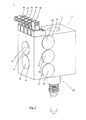
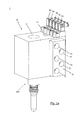
- FIGS Figures 1 to 2b A perspective view of a first embodiment of the device according to the invention for controlling blowing media in a stretch blow molding machine is shown in FIGS Figures 1 to 2b shown.
- the device has a housing block 10 with a first through-bore 11, which is designed to receive a blowing nozzle 100.
- the through hole 11 is cylindrical and extends from the in Fig. 1 shown upper side of the housing block 10 to the underside, not shown.
- control valves 20, 30, 40, 50 and 60 which are in communication with the first through hole 11 and are adapted to selectively connect the received in the through hole 11 blowing nozzle 100 with a respective fluid port.
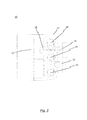
- the fluid connection the valves 20, 30, 40, 50 with the first through hole 11 will be subsequently with reference to the illustrations in the FIGS. 3 to 5 explained.
- the housing block 10 has a number of valves corresponding number of valve channels 12, 13, 14, 15 and 16, which serve to receive the valves 20, 30, 40, 50 and 60 within the housing block 10.
- the valve channels 12, 13, 14, 15 and 16 are each in fluid communication with the first through hole 11, as for example Fig. 3 is apparent.
- Fig. 3 It is shown that the first, second, third, fourth, and fifth valve channels 12, 13, 14, 15, 16 are connected to each other via a second through-hole 17, wherein the second through-hole 17 via a connecting channel 18 with the first through hole 11 in connection stands.
- the second through-bore 17 is designed as a collecting tube since it is in fluid communication with the high-pressure side of each valve or valve channel 12, 13, 14, 15, 16 or 20, 30, 40, 50, 60.
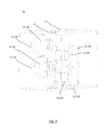
- valve channels 12, 13, 14, 15, 16 to the housing block 10 may, for example, the schematic view according to Fig. 5 be removed. It should be noted at this point that in Fig. 5 , in contrast to Fig. 1 , Only 4 valve channels 12, 13, 14 and 15 are shown for reasons of clarity.
- the valve channels 12, 13, 14, 15 are each aligned substantially perpendicular to the first through hole 11.
- the first valve channel 12 is aligned substantially perpendicular to the second valve channel 13 so that the first and second valve (not in Fig. 5 represented) are arranged crosswise.
- third and fourth valve channels 14 and 15, which are also crosswise, ie substantially perpendicular to each other and are arranged to the first through hole 11.
- each second valve channel 12 and 14 or 13 and 15 is aligned in parallel and intersects with the respective other intermediate valve channels 13, 15 and 12, 14th
- valve channels 12, 13, 14, 15 each have a region of large diameter 12a, 13a, 14a, 15a and a region of smaller diameter 12b, 13b, 14b, 15b.
- the valves 20, 30, 40, 50, 60 preferably each have a control side (61st) facing away from the first through-bore 11 Fig. 4 ), which has a diameter which is greater than the diameter of a first through-bore 11 facing high-pressure side (62 Fig. 4 ) of the respective valve (20, 30, 40, 50, 60).
- the "dead air space" can be particularly well reduced by the crossed valves.
- Fig. 4 it is also the Fig. 4 to take the example of the fifth valve 60, that the valves 20, 30, 40, 50, 60, for example, by a biasing spring (not shown) are biased in the idle state with its high pressure side 62 against the valve seat 161 of the respective valve channel 16. Accordingly, the Valves 20, 30, 40, 50 and 60 are closed in their idle state, ie initially there is no pressurization of the compressed air in the first through hole 11 blowing nozzle 100 instead.
- valves 20, 30, 40, 50, 60 by the in the FIGS. 1 and 2 shown pilot valves 81, 82, 83, 84, 85 are activated, a connection between the respective fluid port 122, 132, 142, 152, 162 and located in the first through hole 11 blowing nozzle 100 is produced, since the valve 20, 30, 40 , 50, 60 from his in Fig. 4 shown rest position is shifted to the right, whereby the high-pressure side portion 62 of the valve 60 is lifted from the valve seat 161 and thus produces a fluid connection to the collecting channel 17.
- the respective pilot valve 81 to 85 may be connected to the control side 61 of the valve 60 via a corresponding control air passage.
- the device according to the invention preferably has a connection block 70, which is detachably connected to the housing block 10.
- the terminal block 70 is configured to connect each of the fluid ports 122, 132, 142, 152, 162 (FIG. Fig. 2b ) to be connected to a connecting line 71, 72, 73, 74 and 75, respectively.
- the connecting lines 71, 72, 73, 74, 75 form a fluid connection with a compressed air reservoir or a vent opening.
- the terminal block 70 is preferably attached to the housing block 10 of the device 1 via fasteners (eg, with mounting screws, not shown).
- the connecting lines 71, 72, 73, 74, 75 can be connected in one working step to the fluid connections 122, 132, 142, 152, 162.
- the present invention is not limited to the specific embodiments shown in the drawings. Much more, this results from a combination of the features disclosed herein.
- the present invention is not limited to the number of five valves or valve channels shown in the figures. Rather, any number of valves can be provided. All that matters is that the valves are arranged "crosswise", that is to say alternately, essentially perpendicular to one another.
Landscapes
- Engineering & Computer Science (AREA)
- Mechanical Engineering (AREA)
- General Engineering & Computer Science (AREA)
- Manufacturing & Machinery (AREA)
- Blow-Moulding Or Thermoforming Of Plastics Or The Like (AREA)
- Multiple-Way Valves (AREA)
Priority Applications (3)
| Application Number | Priority Date | Filing Date | Title |
|---|---|---|---|
| EP13405100.2A EP2837486B1 (fr) | 2013-08-14 | 2013-08-14 | Dispositif de contrôle de fluides soufflés dans une machine d'étirage-soufflage |
| CN201410395234.0A CN104369358B (zh) | 2013-08-14 | 2014-08-12 | 用于控制拉伸吹气机中的吹气介质的装置 |
| US14/458,715 US9221208B2 (en) | 2013-08-14 | 2014-08-13 | Device for controlling blowing mediums in a stretch blow moulding machine |
Applications Claiming Priority (1)
| Application Number | Priority Date | Filing Date | Title |
|---|---|---|---|
| EP13405100.2A EP2837486B1 (fr) | 2013-08-14 | 2013-08-14 | Dispositif de contrôle de fluides soufflés dans une machine d'étirage-soufflage |
Publications (2)
| Publication Number | Publication Date |
|---|---|
| EP2837486A1 true EP2837486A1 (fr) | 2015-02-18 |
| EP2837486B1 EP2837486B1 (fr) | 2018-09-19 |
Family
ID=49034022
Family Applications (1)
| Application Number | Title | Priority Date | Filing Date |
|---|---|---|---|
| EP13405100.2A Active EP2837486B1 (fr) | 2013-08-14 | 2013-08-14 | Dispositif de contrôle de fluides soufflés dans une machine d'étirage-soufflage |
Country Status (3)
| Country | Link |
|---|---|
| US (1) | US9221208B2 (fr) |
| EP (1) | EP2837486B1 (fr) |
| CN (1) | CN104369358B (fr) |
Cited By (3)
| Publication number | Priority date | Publication date | Assignee | Title |
|---|---|---|---|---|
| CN109296781A (zh) * | 2018-10-30 | 2019-02-01 | 安沃驰气动设备(常州)有限公司 | 一种新型吹瓶组合阀 |
| EP3711926A1 (fr) | 2019-03-22 | 2020-09-23 | Eugen Seitz AG | Dispositif de soupape de soufflage pour un dispositif de soufflage |
| US12447665B2 (en) | 2019-03-22 | 2025-10-21 | Eugen Seitz Ag | Blowing valve device of a blow-moulding device |
Families Citing this family (4)
| Publication number | Priority date | Publication date | Assignee | Title |
|---|---|---|---|---|
| DE102017109112A1 (de) * | 2017-04-27 | 2018-10-31 | Norgren Ag | Vorrichtung zur Druckluftsteuerung |
| CN109296784A (zh) * | 2018-10-30 | 2019-02-01 | 安沃驰气动设备(常州)有限公司 | 一种吹瓶组合阀 |
| DE102019110074B4 (de) * | 2019-04-16 | 2022-01-13 | Bürkert Werke GmbH & Co. KG | Dosiereinheit zur Dosierung von Fluiden, Dosierstation, Dosierspitze für eine Dosiereinheit und Verfahren zur Dosierung eines Fluids |
| IT202100027404A1 (it) * | 2021-10-26 | 2023-04-26 | Smi Spa | Gruppo valvola per la soffiatura o stiro-soffiatura di bottiglie in materiale polimerico |
Citations (5)
| Publication number | Priority date | Publication date | Assignee | Title |
|---|---|---|---|---|
| DE20305232U1 (de) * | 2003-04-01 | 2003-05-28 | Festo AG & Co, 73734 Esslingen | Ventilblock |
| US7927093B2 (en) | 2005-08-12 | 2011-04-19 | Sidel Participations | Fluid flow control assembly for a container blowing machine and machine comprising one such assembly |
| US20120199779A1 (en) * | 2009-10-09 | 2012-08-09 | Norgren Gmbh | Valve block assembly for a blow molding system |
| US20120201918A1 (en) * | 2009-10-09 | 2012-08-09 | Christian Elbs | Blow molding valve for a blow molding valve block |
| US20120241012A1 (en) * | 2009-12-18 | 2012-09-27 | Norgren Gmbh | Multiple-stage valve system |
Family Cites Families (4)
| Publication number | Priority date | Publication date | Assignee | Title |
|---|---|---|---|---|
| DE20018500U1 (de) * | 2000-10-28 | 2001-12-13 | KRONES AG, 93073 Neutraubling | Blasmaschine |
| FR2872082B1 (fr) * | 2004-06-23 | 2006-10-06 | Sidel Sas | Installation de soufflage de recipients en materiau thermoplastique |
| DE102004041973B3 (de) * | 2004-08-31 | 2006-01-19 | Krones Ag | Luftrecycling im Blasformprozess |
| DE102009020738A1 (de) * | 2009-05-11 | 2010-11-25 | Krones Ag | Vorrichtung zum Blasformen von Kunststoffvorformlingen mit reduziertem Totvolumen |
-
2013
- 2013-08-14 EP EP13405100.2A patent/EP2837486B1/fr active Active
-
2014
- 2014-08-12 CN CN201410395234.0A patent/CN104369358B/zh active Active
- 2014-08-13 US US14/458,715 patent/US9221208B2/en active Active
Patent Citations (5)
| Publication number | Priority date | Publication date | Assignee | Title |
|---|---|---|---|---|
| DE20305232U1 (de) * | 2003-04-01 | 2003-05-28 | Festo AG & Co, 73734 Esslingen | Ventilblock |
| US7927093B2 (en) | 2005-08-12 | 2011-04-19 | Sidel Participations | Fluid flow control assembly for a container blowing machine and machine comprising one such assembly |
| US20120199779A1 (en) * | 2009-10-09 | 2012-08-09 | Norgren Gmbh | Valve block assembly for a blow molding system |
| US20120201918A1 (en) * | 2009-10-09 | 2012-08-09 | Christian Elbs | Blow molding valve for a blow molding valve block |
| US20120241012A1 (en) * | 2009-12-18 | 2012-09-27 | Norgren Gmbh | Multiple-stage valve system |
Cited By (4)
| Publication number | Priority date | Publication date | Assignee | Title |
|---|---|---|---|---|
| CN109296781A (zh) * | 2018-10-30 | 2019-02-01 | 安沃驰气动设备(常州)有限公司 | 一种新型吹瓶组合阀 |
| CN109296781B (zh) * | 2018-10-30 | 2023-09-22 | 世格流体控制(上海)有限公司 | 一种新型吹瓶组合阀 |
| EP3711926A1 (fr) | 2019-03-22 | 2020-09-23 | Eugen Seitz AG | Dispositif de soupape de soufflage pour un dispositif de soufflage |
| US12447665B2 (en) | 2019-03-22 | 2025-10-21 | Eugen Seitz Ag | Blowing valve device of a blow-moulding device |
Also Published As
| Publication number | Publication date |
|---|---|
| US20150050381A1 (en) | 2015-02-19 |
| CN104369358A (zh) | 2015-02-25 |
| EP2837486B1 (fr) | 2018-09-19 |
| US9221208B2 (en) | 2015-12-29 |
| CN104369358B (zh) | 2018-03-09 |
Similar Documents
| Publication | Publication Date | Title |
|---|---|---|
| EP2837486B1 (fr) | Dispositif de contrôle de fluides soufflés dans une machine d'étirage-soufflage | |
| EP2338671B1 (fr) | Dispositif d'introduction d'air et/ou de moyens d'étanchéification dans un pneu | |
| DE102007059651B4 (de) | Probengeber für die Hochleistungsflüssigkeitschromatographie | |
| DE10206502C1 (de) | Druckgastank mit mehreren Behältern | |
| EP4061624B1 (fr) | Appareil pour transporter de l'air comprimé et/ou un agent d'étanchéité dans un pneu de véhicule et système portable/transportable pour étanchéifier et gonfler des pneus de véhicule | |
| DE102009020738A1 (de) | Vorrichtung zum Blasformen von Kunststoffvorformlingen mit reduziertem Totvolumen | |
| DE69419285T2 (de) | Zu reinigende Gasabführverbindung für Druckgaszylinder | |
| DE102011017739A1 (de) | Verfahren und Vorrichtung zur Anreicherung einer Flüssigkeit mit Gas | |
| DD283074A5 (de) | Druckwechseladsorptionsanlage zum trennen von gasgemischen | |
| DE3781853T2 (de) | Ventilblockzusammenbau. | |
| EP2956242B1 (fr) | Pompe à agent de revêtement et procédé de nettoyage d'une pompe à agent de revêtement | |
| DE10348278A1 (de) | Verfahren und Vorrichtung zur Behandlung eines laufenden Fadens mit einem gas- und dampfförmigen Behandlungsmedium | |
| DE102015110073A1 (de) | Faltenbalgdichtung sowie Arbeitskopf einer Vorrichtung oder Maschine zum Herstellen und/oder Behandeln von Behältern mit einer solchen Faltenbalgdichtung | |
| DE10212407B4 (de) | Tankinternes Kraftstoffpumpensystem | |
| EP0515449B1 (fr) | Dispositif de coupe et de nettoyage d'objets au moyen d'un melange d'eau et d'un produit abrasif sous une haute pression environnante | |
| DE19827883A1 (de) | Baueinheit für eine Druckluftanlage | |
| EP4204805B1 (fr) | Appareil et procédé de dégazage d'un navire de dégazage, et système de test correspondant pour analyse de gaz | |
| EP0743485B1 (fr) | Dispositif de remplissage de bouteilles à gaz pour un autobus opérant au gaz | |
| DE102008005764A1 (de) | Spannvorrichtung für Zugmitteltriebe im Steuertrieb eines Kraftfahrzeuges | |
| DE102007056687A1 (de) | Luftfeder | |
| DE202017102605U1 (de) | Ventilkombination | |
| EP1762364A2 (fr) | Dispositif pour filtrer un fluide, notamment dans des installations de transformation de matières plastiques | |
| DE102009038811B3 (de) | Maschine, insbesondere Behälterbehandlungsmaschine | |
| WO2020094300A1 (fr) | Dispositif de distribution, système et procédé de colmatage et utilisation | |
| DE19540918C2 (de) | Gas-Verdichtungs- und Verteilungseinrichtung |
Legal Events
| Date | Code | Title | Description |
|---|---|---|---|
| 17P | Request for examination filed |
Effective date: 20130814 |
|
| AK | Designated contracting states |
Kind code of ref document: A1 Designated state(s): AL AT BE BG CH CY CZ DE DK EE ES FI FR GB GR HR HU IE IS IT LI LT LU LV MC MK MT NL NO PL PT RO RS SE SI SK SM TR |
|
| AX | Request for extension of the european patent |
Extension state: BA ME |
|
| PUAI | Public reference made under article 153(3) epc to a published international application that has entered the european phase |
Free format text: ORIGINAL CODE: 0009012 |
|
| R17P | Request for examination filed (corrected) |
Effective date: 20150818 |
|
| RBV | Designated contracting states (corrected) |
Designated state(s): AL AT BE BG CH CY CZ DE DK EE ES FI FR GB GR HR HU IE IS IT LI LT LU LV MC MK MT NL NO PL PT RO RS SE SI SK SM TR |
|
| GRAP | Despatch of communication of intention to grant a patent |
Free format text: ORIGINAL CODE: EPIDOSNIGR1 |
|
| STAA | Information on the status of an ep patent application or granted ep patent |
Free format text: STATUS: GRANT OF PATENT IS INTENDED |
|
| RIC1 | Information provided on ipc code assigned before grant |
Ipc: F16K 27/00 20060101ALN20180306BHEP Ipc: B29C 49/46 20060101ALI20180306BHEP Ipc: B29C 49/42 20060101AFI20180306BHEP Ipc: B29K 67/00 20060101ALN20180306BHEP |
|
| INTG | Intention to grant announced |
Effective date: 20180322 |
|
| RIC1 | Information provided on ipc code assigned before grant |
Ipc: B29C 49/42 20060101AFI20180313BHEP Ipc: B29K 67/00 20060101ALN20180313BHEP Ipc: F16K 27/00 20060101ALN20180313BHEP Ipc: B29C 49/46 20060101ALI20180313BHEP |
|
| GRAS | Grant fee paid |
Free format text: ORIGINAL CODE: EPIDOSNIGR3 |
|
| GRAA | (expected) grant |
Free format text: ORIGINAL CODE: 0009210 |
|
| STAA | Information on the status of an ep patent application or granted ep patent |
Free format text: STATUS: THE PATENT HAS BEEN GRANTED |
|
| AK | Designated contracting states |
Kind code of ref document: B1 Designated state(s): AL AT BE BG CH CY CZ DE DK EE ES FI FR GB GR HR HU IE IS IT LI LT LU LV MC MK MT NL NO PL PT RO RS SE SI SK SM TR |
|
| REG | Reference to a national code |
Ref country code: GB Ref legal event code: FG4D Free format text: NOT ENGLISH |
|
| REG | Reference to a national code |
Ref country code: CH Ref legal event code: EP Ref country code: CH Ref legal event code: NV Representative=s name: ISLER AND PEDRAZZINI AG, CH |
|
| REG | Reference to a national code |
Ref country code: AT Ref legal event code: REF Ref document number: 1042741 Country of ref document: AT Kind code of ref document: T Effective date: 20181015 |
|
| REG | Reference to a national code |
Ref country code: IE Ref legal event code: FG4D Free format text: LANGUAGE OF EP DOCUMENT: GERMAN |
|
| REG | Reference to a national code |
Ref country code: DE Ref legal event code: R096 Ref document number: 502013011109 Country of ref document: DE |
|
| REG | Reference to a national code |
Ref country code: NL Ref legal event code: MP Effective date: 20180919 |
|
| PG25 | Lapsed in a contracting state [announced via postgrant information from national office to epo] |
Ref country code: LT Free format text: LAPSE BECAUSE OF FAILURE TO SUBMIT A TRANSLATION OF THE DESCRIPTION OR TO PAY THE FEE WITHIN THE PRESCRIBED TIME-LIMIT Effective date: 20180919 Ref country code: FI Free format text: LAPSE BECAUSE OF FAILURE TO SUBMIT A TRANSLATION OF THE DESCRIPTION OR TO PAY THE FEE WITHIN THE PRESCRIBED TIME-LIMIT Effective date: 20180919 Ref country code: GR Free format text: LAPSE BECAUSE OF FAILURE TO SUBMIT A TRANSLATION OF THE DESCRIPTION OR TO PAY THE FEE WITHIN THE PRESCRIBED TIME-LIMIT Effective date: 20181220 Ref country code: RS Free format text: LAPSE BECAUSE OF FAILURE TO SUBMIT A TRANSLATION OF THE DESCRIPTION OR TO PAY THE FEE WITHIN THE PRESCRIBED TIME-LIMIT Effective date: 20180919 Ref country code: BG Free format text: LAPSE BECAUSE OF FAILURE TO SUBMIT A TRANSLATION OF THE DESCRIPTION OR TO PAY THE FEE WITHIN THE PRESCRIBED TIME-LIMIT Effective date: 20181219 Ref country code: NO Free format text: LAPSE BECAUSE OF FAILURE TO SUBMIT A TRANSLATION OF THE DESCRIPTION OR TO PAY THE FEE WITHIN THE PRESCRIBED TIME-LIMIT Effective date: 20181219 Ref country code: SE Free format text: LAPSE BECAUSE OF FAILURE TO SUBMIT A TRANSLATION OF THE DESCRIPTION OR TO PAY THE FEE WITHIN THE PRESCRIBED TIME-LIMIT Effective date: 20180919 |
|
| REG | Reference to a national code |
Ref country code: LT Ref legal event code: MG4D |
|
| PG25 | Lapsed in a contracting state [announced via postgrant information from national office to epo] |
Ref country code: HR Free format text: LAPSE BECAUSE OF FAILURE TO SUBMIT A TRANSLATION OF THE DESCRIPTION OR TO PAY THE FEE WITHIN THE PRESCRIBED TIME-LIMIT Effective date: 20180919 Ref country code: LV Free format text: LAPSE BECAUSE OF FAILURE TO SUBMIT A TRANSLATION OF THE DESCRIPTION OR TO PAY THE FEE WITHIN THE PRESCRIBED TIME-LIMIT Effective date: 20180919 Ref country code: AL Free format text: LAPSE BECAUSE OF FAILURE TO SUBMIT A TRANSLATION OF THE DESCRIPTION OR TO PAY THE FEE WITHIN THE PRESCRIBED TIME-LIMIT Effective date: 20180919 |
|
| PG25 | Lapsed in a contracting state [announced via postgrant information from national office to epo] |
Ref country code: EE Free format text: LAPSE BECAUSE OF FAILURE TO SUBMIT A TRANSLATION OF THE DESCRIPTION OR TO PAY THE FEE WITHIN THE PRESCRIBED TIME-LIMIT Effective date: 20180919 Ref country code: IS Free format text: LAPSE BECAUSE OF FAILURE TO SUBMIT A TRANSLATION OF THE DESCRIPTION OR TO PAY THE FEE WITHIN THE PRESCRIBED TIME-LIMIT Effective date: 20190119 Ref country code: PL Free format text: LAPSE BECAUSE OF FAILURE TO SUBMIT A TRANSLATION OF THE DESCRIPTION OR TO PAY THE FEE WITHIN THE PRESCRIBED TIME-LIMIT Effective date: 20180919 Ref country code: ES Free format text: LAPSE BECAUSE OF FAILURE TO SUBMIT A TRANSLATION OF THE DESCRIPTION OR TO PAY THE FEE WITHIN THE PRESCRIBED TIME-LIMIT Effective date: 20180919 Ref country code: NL Free format text: LAPSE BECAUSE OF FAILURE TO SUBMIT A TRANSLATION OF THE DESCRIPTION OR TO PAY THE FEE WITHIN THE PRESCRIBED TIME-LIMIT Effective date: 20180919 Ref country code: RO Free format text: LAPSE BECAUSE OF FAILURE TO SUBMIT A TRANSLATION OF THE DESCRIPTION OR TO PAY THE FEE WITHIN THE PRESCRIBED TIME-LIMIT Effective date: 20180919 |
|
| PG25 | Lapsed in a contracting state [announced via postgrant information from national office to epo] |
Ref country code: PT Free format text: LAPSE BECAUSE OF FAILURE TO SUBMIT A TRANSLATION OF THE DESCRIPTION OR TO PAY THE FEE WITHIN THE PRESCRIBED TIME-LIMIT Effective date: 20190119 Ref country code: SM Free format text: LAPSE BECAUSE OF FAILURE TO SUBMIT A TRANSLATION OF THE DESCRIPTION OR TO PAY THE FEE WITHIN THE PRESCRIBED TIME-LIMIT Effective date: 20180919 Ref country code: SK Free format text: LAPSE BECAUSE OF FAILURE TO SUBMIT A TRANSLATION OF THE DESCRIPTION OR TO PAY THE FEE WITHIN THE PRESCRIBED TIME-LIMIT Effective date: 20180919 |
|
| REG | Reference to a national code |
Ref country code: DE Ref legal event code: R097 Ref document number: 502013011109 Country of ref document: DE |
|
| PLBE | No opposition filed within time limit |
Free format text: ORIGINAL CODE: 0009261 |
|
| STAA | Information on the status of an ep patent application or granted ep patent |
Free format text: STATUS: NO OPPOSITION FILED WITHIN TIME LIMIT |
|
| PG25 | Lapsed in a contracting state [announced via postgrant information from national office to epo] |
Ref country code: DK Free format text: LAPSE BECAUSE OF FAILURE TO SUBMIT A TRANSLATION OF THE DESCRIPTION OR TO PAY THE FEE WITHIN THE PRESCRIBED TIME-LIMIT Effective date: 20180919 |
|
| 26N | No opposition filed |
Effective date: 20190620 |
|
| PG25 | Lapsed in a contracting state [announced via postgrant information from national office to epo] |
Ref country code: SI Free format text: LAPSE BECAUSE OF FAILURE TO SUBMIT A TRANSLATION OF THE DESCRIPTION OR TO PAY THE FEE WITHIN THE PRESCRIBED TIME-LIMIT Effective date: 20180919 |
|
| PG25 | Lapsed in a contracting state [announced via postgrant information from national office to epo] |
Ref country code: TR Free format text: LAPSE BECAUSE OF FAILURE TO SUBMIT A TRANSLATION OF THE DESCRIPTION OR TO PAY THE FEE WITHIN THE PRESCRIBED TIME-LIMIT Effective date: 20180919 |
|
| GBPC | Gb: european patent ceased through non-payment of renewal fee |
Effective date: 20190814 |
|
| PG25 | Lapsed in a contracting state [announced via postgrant information from national office to epo] |
Ref country code: MC Free format text: LAPSE BECAUSE OF FAILURE TO SUBMIT A TRANSLATION OF THE DESCRIPTION OR TO PAY THE FEE WITHIN THE PRESCRIBED TIME-LIMIT Effective date: 20180919 Ref country code: LU Free format text: LAPSE BECAUSE OF NON-PAYMENT OF DUE FEES Effective date: 20190814 |
|
| REG | Reference to a national code |
Ref country code: BE Ref legal event code: MM Effective date: 20190831 |
|
| PG25 | Lapsed in a contracting state [announced via postgrant information from national office to epo] |
Ref country code: IE Free format text: LAPSE BECAUSE OF NON-PAYMENT OF DUE FEES Effective date: 20190814 |
|
| PG25 | Lapsed in a contracting state [announced via postgrant information from national office to epo] |
Ref country code: GB Free format text: LAPSE BECAUSE OF NON-PAYMENT OF DUE FEES Effective date: 20190814 Ref country code: BE Free format text: LAPSE BECAUSE OF NON-PAYMENT OF DUE FEES Effective date: 20190831 |
|
| REG | Reference to a national code |
Ref country code: AT Ref legal event code: MM01 Ref document number: 1042741 Country of ref document: AT Kind code of ref document: T Effective date: 20190814 |
|
| PGFP | Annual fee paid to national office [announced via postgrant information from national office to epo] |
Ref country code: CZ Payment date: 20200807 Year of fee payment: 8 |
|
| PG25 | Lapsed in a contracting state [announced via postgrant information from national office to epo] |
Ref country code: AT Free format text: LAPSE BECAUSE OF NON-PAYMENT OF DUE FEES Effective date: 20190814 |
|
| PG25 | Lapsed in a contracting state [announced via postgrant information from national office to epo] |
Ref country code: CY Free format text: LAPSE BECAUSE OF FAILURE TO SUBMIT A TRANSLATION OF THE DESCRIPTION OR TO PAY THE FEE WITHIN THE PRESCRIBED TIME-LIMIT Effective date: 20180919 |
|
| PG25 | Lapsed in a contracting state [announced via postgrant information from national office to epo] |
Ref country code: MT Free format text: LAPSE BECAUSE OF FAILURE TO SUBMIT A TRANSLATION OF THE DESCRIPTION OR TO PAY THE FEE WITHIN THE PRESCRIBED TIME-LIMIT Effective date: 20180919 Ref country code: HU Free format text: LAPSE BECAUSE OF FAILURE TO SUBMIT A TRANSLATION OF THE DESCRIPTION OR TO PAY THE FEE WITHIN THE PRESCRIBED TIME-LIMIT; INVALID AB INITIO Effective date: 20130814 |
|
| PG25 | Lapsed in a contracting state [announced via postgrant information from national office to epo] |
Ref country code: CZ Free format text: LAPSE BECAUSE OF NON-PAYMENT OF DUE FEES Effective date: 20210814 |
|
| PG25 | Lapsed in a contracting state [announced via postgrant information from national office to epo] |
Ref country code: MK Free format text: LAPSE BECAUSE OF FAILURE TO SUBMIT A TRANSLATION OF THE DESCRIPTION OR TO PAY THE FEE WITHIN THE PRESCRIBED TIME-LIMIT Effective date: 20180919 |
|
| P01 | Opt-out of the competence of the unified patent court (upc) registered |
Effective date: 20230519 |
|
| PGFP | Annual fee paid to national office [announced via postgrant information from national office to epo] |
Ref country code: DE Payment date: 20250820 Year of fee payment: 13 |
|
| PGFP | Annual fee paid to national office [announced via postgrant information from national office to epo] |
Ref country code: IT Payment date: 20250820 Year of fee payment: 13 |
|
| PGFP | Annual fee paid to national office [announced via postgrant information from national office to epo] |
Ref country code: FR Payment date: 20250829 Year of fee payment: 13 |
|
| PGFP | Annual fee paid to national office [announced via postgrant information from national office to epo] |
Ref country code: CH Payment date: 20250901 Year of fee payment: 13 |
|
| REG | Reference to a national code |
Ref country code: DE Ref legal event code: R082 Ref document number: 502013011109 Country of ref document: DE Representative=s name: TERGAU & WALKENHORST INTELLECTUAL PROPERTY GMB, DE |