EP2837773A1 - Ringspaltfüller und zugehörige Stufe und Gasturbinentriebwerk - Google Patents
Ringspaltfüller und zugehörige Stufe und Gasturbinentriebwerk Download PDFInfo
- Publication number
- EP2837773A1 EP2837773A1 EP14180628.1A EP14180628A EP2837773A1 EP 2837773 A1 EP2837773 A1 EP 2837773A1 EP 14180628 A EP14180628 A EP 14180628A EP 2837773 A1 EP2837773 A1 EP 2837773A1
- Authority
- EP
- European Patent Office
- Prior art keywords
- lid
- engageable portion
- annulus filler
- engine
- rotor disc
- Prior art date
- Legal status (The legal status is an assumption and is not a legal conclusion. Google has not performed a legal analysis and makes no representation as to the accuracy of the status listed.)
- Granted
Links
- 239000000945 filler Substances 0.000 title claims abstract description 58
- 230000004888 barrier function Effects 0.000 claims abstract description 22
- 230000007797 corrosion Effects 0.000 claims abstract description 21
- 238000005260 corrosion Methods 0.000 claims abstract description 21
- 239000000463 material Substances 0.000 claims abstract description 8
- 239000011208 reinforced composite material Substances 0.000 claims description 10
- 239000004642 Polyimide Substances 0.000 claims description 3
- 239000003365 glass fiber Substances 0.000 claims description 3
- 239000004033 plastic Substances 0.000 claims description 3
- 229920001721 polyimide Polymers 0.000 claims description 3
- 239000011160 polymer matrix composite Substances 0.000 claims description 3
- 229920013657 polymer matrix composite Polymers 0.000 claims description 3
- 239000002131 composite material Substances 0.000 description 11
- OKTJSMMVPCPJKN-UHFFFAOYSA-N Carbon Chemical compound [C] OKTJSMMVPCPJKN-UHFFFAOYSA-N 0.000 description 10
- 229910052799 carbon Inorganic materials 0.000 description 10
- 239000000835 fiber Substances 0.000 description 9
- 239000002184 metal Substances 0.000 description 4
- 229910052751 metal Inorganic materials 0.000 description 4
- 230000015572 biosynthetic process Effects 0.000 description 3
- 238000002485 combustion reaction Methods 0.000 description 3
- 230000000694 effects Effects 0.000 description 3
- 238000005755 formation reaction Methods 0.000 description 3
- 230000001141 propulsive effect Effects 0.000 description 3
- 230000009286 beneficial effect Effects 0.000 description 2
- 230000000295 complement effect Effects 0.000 description 2
- 229910000838 Al alloy Inorganic materials 0.000 description 1
- 230000004323 axial length Effects 0.000 description 1
- 230000006835 compression Effects 0.000 description 1
- 238000007906 compression Methods 0.000 description 1
- 238000010276 construction Methods 0.000 description 1
- 238000013016 damping Methods 0.000 description 1
- 230000001747 exhibiting effect Effects 0.000 description 1
- 239000000446 fuel Substances 0.000 description 1
- 239000011521 glass Substances 0.000 description 1
- 239000003562 lightweight material Substances 0.000 description 1
- 230000014759 maintenance of location Effects 0.000 description 1
- 238000004519 manufacturing process Methods 0.000 description 1
- 239000007769 metal material Substances 0.000 description 1
- 239000000203 mixture Substances 0.000 description 1
- 238000012986 modification Methods 0.000 description 1
- 230000004048 modification Effects 0.000 description 1
- 229920000642 polymer Polymers 0.000 description 1
- 230000002787 reinforcement Effects 0.000 description 1
- 238000007363 ring formation reaction Methods 0.000 description 1
Images


Classifications
-
- F—MECHANICAL ENGINEERING; LIGHTING; HEATING; WEAPONS; BLASTING
- F01—MACHINES OR ENGINES IN GENERAL; ENGINE PLANTS IN GENERAL; STEAM ENGINES
- F01D—NON-POSITIVE DISPLACEMENT MACHINES OR ENGINES, e.g. STEAM TURBINES
- F01D11/00—Preventing or minimising internal leakage of working-fluid, e.g. between stages
- F01D11/005—Sealing means between non relatively rotating elements
- F01D11/006—Sealing the gap between rotor blades or blades and rotor
- F01D11/008—Sealing the gap between rotor blades or blades and rotor by spacer elements between the blades, e.g. independent interblade platforms
-
- F—MECHANICAL ENGINEERING; LIGHTING; HEATING; WEAPONS; BLASTING
- F05—INDEXING SCHEMES RELATING TO ENGINES OR PUMPS IN VARIOUS SUBCLASSES OF CLASSES F01-F04
- F05D—INDEXING SCHEME FOR ASPECTS RELATING TO NON-POSITIVE-DISPLACEMENT MACHINES OR ENGINES, GAS-TURBINES OR JET-PROPULSION PLANTS
- F05D2220/00—Application
- F05D2220/30—Application in turbines
- F05D2220/36—Application in turbines specially adapted for the fan of turbofan engines
-
- F—MECHANICAL ENGINEERING; LIGHTING; HEATING; WEAPONS; BLASTING
- F05—INDEXING SCHEMES RELATING TO ENGINES OR PUMPS IN VARIOUS SUBCLASSES OF CLASSES F01-F04
- F05D—INDEXING SCHEME FOR ASPECTS RELATING TO NON-POSITIVE-DISPLACEMENT MACHINES OR ENGINES, GAS-TURBINES OR JET-PROPULSION PLANTS
- F05D2260/00—Function
- F05D2260/95—Preventing corrosion
-
- F—MECHANICAL ENGINEERING; LIGHTING; HEATING; WEAPONS; BLASTING
- F05—INDEXING SCHEMES RELATING TO ENGINES OR PUMPS IN VARIOUS SUBCLASSES OF CLASSES F01-F04
- F05D—INDEXING SCHEME FOR ASPECTS RELATING TO NON-POSITIVE-DISPLACEMENT MACHINES OR ENGINES, GAS-TURBINES OR JET-PROPULSION PLANTS
- F05D2300/00—Materials; Properties thereof
- F05D2300/40—Organic materials
- F05D2300/43—Synthetic polymers, e.g. plastics; Rubber
- F05D2300/434—Polyimides, e.g. AURUM
-
- F—MECHANICAL ENGINEERING; LIGHTING; HEATING; WEAPONS; BLASTING
- F05—INDEXING SCHEMES RELATING TO ENGINES OR PUMPS IN VARIOUS SUBCLASSES OF CLASSES F01-F04
- F05D—INDEXING SCHEME FOR ASPECTS RELATING TO NON-POSITIVE-DISPLACEMENT MACHINES OR ENGINES, GAS-TURBINES OR JET-PROPULSION PLANTS
- F05D2300/00—Materials; Properties thereof
- F05D2300/60—Properties or characteristics given to material by treatment or manufacturing
- F05D2300/603—Composites; e.g. fibre-reinforced
Definitions
- the present invention relates to annulus fillers for bridging gaps between adjacent blades of a gas turbine engine.
- a compressor rotor stage in a gas turbine engine comprises a plurality of radially extending blades mounted on a rotor disc.
- the blades are mounted on the disc by inserting a root portion of the blade in a complementary retention groove in the outer face of the disc periphery.
- annulus fillers can be used to bridge the spaces between adjacent blades.
- Annulus fillers of this type are commonly used in the fan stage of gas turbine engines.
- the fillers may be manufactured from relatively lightweight materials and, in the event of damage, may be replaced independently of the blades.
- Annulus fillers come in various shapes and sizes depending on the design and construction of the gas turbine engine into which they are inserted.
- annulus fillers have an outer lid which defines an airflow surface for air being drawn through the engine, the lid having a leading edge and a trailing edge in an axial airflow direction, and a support arrangement which connects directly or indirectly to the rotor disc to support the lid thereon.
- the support arrangement may comprise one or more of a pin formation (e.g. for attaching the front of the filler to the disc), a mounting ring formation (e.g. for attaching the rear of the filler to the disc), and a hook formation (e.g. for attaching the underside of the filler to the disc).
- Filler release may result from bird strike on the filler or from excessive blade movement.
- the filler can be formed of lightweight carbon fibre reinforced composite material.
- the filler is formed of other materials such as other polymer matrix composites, a problem can then arise of galvanic corrosion between the filler and adjacent, typically metallic, parts of the engine. Similarly, this effect can be seen in reverse with composite adjacent parts of the engine and metallic annulus fillers.
- a first aspect of the invention provides an annulus filler for mounting to a rotor disc of a gas turbine engine and bridging the gap between two adjacent blades attached to the rotor disc, the annulus filler having:
- a second aspect of the invention provides a stage for a gas turbine engine having:
- a third aspect of the invention provides a gas turbine engine having the stage of the second aspect.
- the filler is for mounting to a fan disc and bridging the gap between two adjacent fan blades attached to the fan disc.
- the adjacent engine parts may be metal parts, e.g. aluminium alloy parts.
- the adjacent engine part of the first engageable portion may include a nosecone fairing or a makeup piece of a nosecone fairing.
- the adjacent engine part of the second engageable portion may be a fan rear seal.
- the annulus filler may be for use with metallic or composite blades.
- the galvanic corrosion barrier of the first engageable portion may have a reduced coefficient of friction relative to the carbon fibre reinforced composite material to facilitate relative movement between the first engageable portion and the respective adjacent engine part. In this way, wear between the first engageable portion and the respective adjacent engine part can be reduced.
- the galvanic corrosion barrier of the second engageable portion may have an increased coefficient of friction relative to the carbon fibre reinforced composite material to reduce relative movement between the second engageable portion and the respective adjacent engine part.
- the second engageable portion can help to dampen any undesirable motion of the respective adjacent engine part, such as flutter.
- the second engageable portion may be spaced a distance radially inwardly from the respective adjacent engine part at cold build, but the filler may be configured such that, under the centrifugal loading experienced by the filler when the engine rotates, the second engageable portion moves radially outwardly to engage the respective adjacent engine part.
- the support arrangement of the filler may include one or more straps which, in use, hook onto corresponding formations of the rotor disc.
- the lid of the annulus filler, and optionally the support arrangement as well, may be substantially entirely formed from polymer matrix composite material, such as carbon fibre reinforced composite material.
- the galvanic corrosion barrier of the first engageable portion may be formed from a polyimide-based plastic. Additionally or alternatively, the galvanic corrosion barrier of the second engageable portion may be formed from a glass fibre reinforced composite material.
- the glass fibre reinforced composite material may be co-moulded with the carbon fibre reinforced composite material.
- a three-shaft ducted fan gas turbine engine incorporating the invention is generally indicated at 10 and has a principal and rotational axis X-X.
- the engine comprises, in axial flow series, an air intake 11, a propulsive fan 12, an intermediate pressure compressor 13, a high-pressure compressor 14, combustion equipment 15, a high-pressure turbine 16, an intermediate pressure turbine 17, a low-pressure turbine 18 and a core engine exhaust nozzle 19.
- a nacelle 21 generally surrounds the engine 10 and defines the intake 11, a bypass duct 22 and a bypass exhaust nozzle 23.
- the invention can also be applied to other forms of gas turbine engine, such as two-shaft engines.
- air entering the intake 11 is accelerated by the fan 12 to produce two air flows: a first air flow A into the intermediate pressure compressor 13 and a second air flow B which passes through the bypass duct 22 to provide propulsive thrust.
- the intermediate pressure compressor 13 compresses the air flow A directed into it before delivering that air to the high pressure compressor 14 where further compression takes place.
- the compressed air exhausted from the high-pressure compressor 14 is directed into the combustion equipment 15 where it is mixed with fuel and the mixture combusted.
- the resultant hot combustion products then expand through, and thereby drive the high, intermediate and low-pressure turbines 16, 17, 18 before being exhausted through the nozzle 19 to provide additional propulsive thrust.
- the high, intermediate and low-pressure turbines respectively drive the high and intermediate pressure compressors 14, 13 and the fan 12 by suitable interconnecting shafts.
- Annulus fillers may be used to bridge the spaces between adjacent blades, for example at the fan 12. This is to ensure a smooth radially inner surface for air to flow over as it passes through the fan 12.
- Fig. 2 shows an example annulus filler of the present invention.
- the annulus filler 100 sits between two fan blades 25 and is formed from carbon fibre reinforced composite material.
- carbon fibre reinforced composite material such as polyethylene, polypropylene, polymethyl methacrylate, polymethyl methacrylate, polymethyl methacrylate, polymethyl methacrylate, polymethyl methacrylate, polymethyl methacrylate, polymethyl methacrylate, polymethyl methacrylate, polystylene-based polystylene, polystylene-based composite, polystylene-based composite and metallic material options can also be used for forming the filler.
- the filler 100 comprises an outer lid 30 which defines an airflow surface for air being drawn through the gas turbine engine 10, and a support arrangement which includes a body part 32 extending the axial length of the lid.
- the support arrangement of the filler also includes two axially spaced straps 36 at the radially inward side of the body part 32 which join to complementary hooks 38 on a rotor disc 34.
- the support arrangement and the rotor disc 34 may each have only one strap/hook, or they may each have more than two straps/hooks.
- the body part 32 and the lid 30 form a stiff and lightweight box-like structure, which is able to spread and resist the loads on the filler 100.
- the box-like structure advantageously promotes in-plane tension loading of its composite material under centrifugal loads.
- the box-like structure can be formed without internal features.
- the box-like structure, particularly if formed without internal features, is also relatively easy to manufacture, e.g. from an annular arrangement of continuous fibre reinforcement which can then be moulded and machined.
- the lid may be stitched or z-pinned to the rest of the filler. This can improve the through-thickness strength of the box-like structure, which may be beneficial for hail and birdstrike protection.
- the support arrangement further includes a first engageable portion 40 at the leading edge of the lid 30 and a second engageable portion 42 at the trailing edge of the lid.
- the first engageable portion abuts with a support ring 44 attached to the rotor disc 34 and has a pin 43 which fits into a receiving hole formed in the support ring.
- the first engageable portion also engages a makeup piece 45 which forms an aerodynamic surface between the lid 30 and a spinner fairing 47. Alternatively, the spinner fairing itself may be extended so as to engage with the annulus filler.
- the second engageable portion engages, in use, with a fan rear seal 46 also attached to rotor disc 34.
- the fan blades 25 may be metallic or a composite material, e.g. carbon fibre reinforced composite material.
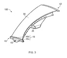
- a first galvanic corrosion barrier 48 is provided at the first engageable portion 40, as illustrated in Fig. 3 .
- the first galvanic corrosion barrier 48 is in two parts, a first part 48a being located where the first engageable portion abuts with the support ring 44, and a second part 48b being located where the first engageable portion engages the makeup piece 45.
- the barrier helps to prevent corrosion by preventing direct contact between the carbon fibres of the composite material of the filler 100 and the metal of the support ring and the makeup piece. However, relative to the composite material, the barrier also has a lower coefficient of friction for sliding against metal. When the filler pivots about the pin 43 (e.g.
- a suitable material for the low friction first galvanic corrosion barrier 48 can be a polyimide-based plastic, such as VespelTM. However, other materials exhibiting similar characteristics of durability and low friction are also possible.
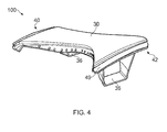
- a second galvanic corrosion barrier 49 is provided at the second engageable portion 42, as illustrated in Fig. 4 .
- the second barrier 49 also helps to prevent corrosion by preventing direct contact between the carbon fibres of the composite material of the filler 100 and the metal of the fan rear seal 46.
- the second barrier has a higher coefficient of friction relative to the composite material than the first barrier 48, and provides increased friction at the interface between the second engageable portion 42 and the fan rear seal.
- the second barrier can be a woven glass composite layer, co-moulded with filler outer part 30. The increased friction allows the filler to act as a frictional damper to the fan rear seal. This in turn reduces flutter in the fan rear seal.
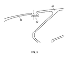
- the second engageable portion 42 fits underneath the fan rear seal 46 and, when the engine is stationary, is spaced a distance radially inwardly therefrom.
- a nominal cold build clearance may be in the range from 0.5-5.0 mm.
- the second engageable portion 42 moves outwardly under centrifugal loading.
- a certain engine speed e.g. about 800 rpm
- the second engageable portion contacts the fan rear seal 46, and begins to exert a force on the seal.
- the effect of this force is to change the unsupported length of the seal, as well as to provide a resistive force to any motion, harmonic or otherwise, of the seal.
- the resistance to such motion is enhanced by the relatively high coefficient of friction of the second barrier 49.
- damping effects are beneficial to the seal and can increase its life by ⁇ 50%.
Landscapes
- Engineering & Computer Science (AREA)
- Mechanical Engineering (AREA)
- General Engineering & Computer Science (AREA)
- Structures Of Non-Positive Displacement Pumps (AREA)
Applications Claiming Priority (1)
| Application Number | Priority Date | Filing Date | Title |
|---|---|---|---|
| GBGB1314540.4A GB201314540D0 (en) | 2013-08-14 | 2013-08-14 | Annulus filler |
Publications (2)
| Publication Number | Publication Date |
|---|---|
| EP2837773A1 true EP2837773A1 (de) | 2015-02-18 |
| EP2837773B1 EP2837773B1 (de) | 2016-11-16 |
Family
ID=49262151
Family Applications (1)
| Application Number | Title | Priority Date | Filing Date |
|---|---|---|---|
| EP14180628.1A Not-in-force EP2837773B1 (de) | 2013-08-14 | 2014-08-12 | Ringspaltfüller und zugehörige Stufe und Gasturbinentriebwerk |
Country Status (3)
| Country | Link |
|---|---|
| US (1) | US20150050151A1 (de) |
| EP (1) | EP2837773B1 (de) |
| GB (1) | GB201314540D0 (de) |
Cited By (2)
| Publication number | Priority date | Publication date | Assignee | Title |
|---|---|---|---|---|
| EP3663530A1 (de) * | 2018-12-07 | 2020-06-10 | Safran Aircraft Engines | Fan mit zwischenschaufelplatform |
| FR3102796A1 (fr) * | 2019-10-30 | 2021-05-07 | Safran Aircraft Engines | Plateformes inter-aubes |
Families Citing this family (3)
| Publication number | Priority date | Publication date | Assignee | Title |
|---|---|---|---|---|
| US12012857B2 (en) | 2022-10-14 | 2024-06-18 | Rtx Corporation | Platform for an airfoil of a gas turbine engine |
| US12421860B2 (en) | 2023-04-27 | 2025-09-23 | Rolls-Royce Plc | Annulus filler for a gas turbine engine |
| US12352175B2 (en) | 2023-07-04 | 2025-07-08 | Rolls-Royce Plc | Annulus filler for a gas turbine engine |
Citations (6)
| Publication number | Priority date | Publication date | Assignee | Title |
|---|---|---|---|---|
| EP1013886A2 (de) * | 1998-12-24 | 2000-06-28 | ROLLS-ROYCE plc | Zwischenschaufelplattform |
| EP2253802A2 (de) * | 2009-05-18 | 2010-11-24 | Rolls-Royce plc | Zwischenstück eines Gasturbinenrotors |
| EP2463482A2 (de) * | 2010-12-09 | 2012-06-13 | Rolls-Royce PLC | Ringförmiges Füllerelement für eine Rotorscheibe eines Gasturbinentriebwerks |
| EP2503102A2 (de) * | 2011-03-25 | 2012-09-26 | Rolls-Royce plc | Rotor mit Plattformen zwischen den Schaufeln |
| EP2511479A2 (de) * | 2011-04-14 | 2012-10-17 | Rolls-Royce plc | Ringförmiges Füllsystem |
| EP2594773A2 (de) * | 2011-11-15 | 2013-05-22 | Rolls-Royce plc | Ringspalthalter |
Family Cites Families (2)
| Publication number | Priority date | Publication date | Assignee | Title |
|---|---|---|---|---|
| GB0802834D0 (en) * | 2008-02-18 | 2008-03-26 | Rolls Royce Plc | Annulus filler |
| GB201020230D0 (en) * | 2010-11-30 | 2011-01-12 | Rolls Royce Plc | Nose cone assembly |
-
2013
- 2013-08-14 GB GBGB1314540.4A patent/GB201314540D0/en not_active Ceased
-
2014
- 2014-08-12 EP EP14180628.1A patent/EP2837773B1/de not_active Not-in-force
- 2014-08-12 US US14/457,569 patent/US20150050151A1/en not_active Abandoned
Patent Citations (6)
| Publication number | Priority date | Publication date | Assignee | Title |
|---|---|---|---|---|
| EP1013886A2 (de) * | 1998-12-24 | 2000-06-28 | ROLLS-ROYCE plc | Zwischenschaufelplattform |
| EP2253802A2 (de) * | 2009-05-18 | 2010-11-24 | Rolls-Royce plc | Zwischenstück eines Gasturbinenrotors |
| EP2463482A2 (de) * | 2010-12-09 | 2012-06-13 | Rolls-Royce PLC | Ringförmiges Füllerelement für eine Rotorscheibe eines Gasturbinentriebwerks |
| EP2503102A2 (de) * | 2011-03-25 | 2012-09-26 | Rolls-Royce plc | Rotor mit Plattformen zwischen den Schaufeln |
| EP2511479A2 (de) * | 2011-04-14 | 2012-10-17 | Rolls-Royce plc | Ringförmiges Füllsystem |
| EP2594773A2 (de) * | 2011-11-15 | 2013-05-22 | Rolls-Royce plc | Ringspalthalter |
Non-Patent Citations (1)
| Title |
|---|
| HUTTUNEN-SAARIVIRTA E ET AL: "Corrosion protection of galvanized steel by polyimide coatings: EIS and SEM investigations", PROGRESS IN ORGANIC COATINGS, ELSEVIER BV, NL, vol. 72, no. 3, 18 April 2011 (2011-04-18), pages 269 - 278, XP028312757, ISSN: 0300-9440, [retrieved on 20110422], DOI: 10.1016/J.PORGCOAT.2011.04.015 * |
Cited By (4)
| Publication number | Priority date | Publication date | Assignee | Title |
|---|---|---|---|---|
| EP3663530A1 (de) * | 2018-12-07 | 2020-06-10 | Safran Aircraft Engines | Fan mit zwischenschaufelplatform |
| FR3089548A1 (fr) * | 2018-12-07 | 2020-06-12 | Safran Aircraft Engines | Soufflante comprenant une plateforme inter-aubes fixee a l’amont par une virole |
| US11162418B2 (en) | 2018-12-07 | 2021-11-02 | Safran Aircraft Engines | Fan comprising an inter-blade platform attached upstream by a ferrule |
| FR3102796A1 (fr) * | 2019-10-30 | 2021-05-07 | Safran Aircraft Engines | Plateformes inter-aubes |
Also Published As
| Publication number | Publication date |
|---|---|
| US20150050151A1 (en) | 2015-02-19 |
| EP2837773B1 (de) | 2016-11-16 |
| GB201314540D0 (en) | 2013-09-25 |
Similar Documents
| Publication | Publication Date | Title |
|---|---|---|
| EP2837772B1 (de) | Ringspaltfüller und zugehörige Stufe und Gasturbinentriebwerk | |
| US9752449B2 (en) | Annulus filler | |
| US8231328B2 (en) | Fan casing for a gas turbine engine | |
| US10358929B2 (en) | Composite airfoil | |
| US8297912B2 (en) | Fan casing for a gas turbine engine | |
| US8827651B2 (en) | Annulus filler | |
| US9745851B2 (en) | Metal leading edge on composite blade airfoil and shank | |
| US9482095B2 (en) | Web connected dual aerofoil members | |
| US20120263595A1 (en) | Annulus filler system | |
| EP2837773B1 (de) | Ringspaltfüller und zugehörige Stufe und Gasturbinentriebwerk | |
| US20120148388A1 (en) | Annulus filler | |
| US20140086751A1 (en) | Annulus filler for axial flow machine | |
| US10125616B2 (en) | Fan blade for an aircraft engine | |
| JP6050139B2 (ja) | ターボ機械ブレード用の抵抗バンド | |
| CN102116175A (zh) | 用于冲击区域增强的系统 | |
| US5137426A (en) | Blade shroud deformable protective coating | |
| US11306601B2 (en) | Pinned airfoil for gas turbine engines | |
| EP2896794B1 (de) | Blisk | |
| US11428105B2 (en) | Airfoil with integral platform for gas turbine engines | |
| US11359500B2 (en) | Rotor assembly with structural platforms for gas turbine engines | |
| CA2844369C (en) | Rotor blades for gas turbine engines | |
| US10161419B2 (en) | Fan casing assembly | |
| GB2484988A (en) | Annulus filler for gas turbine engine rotor disc |
Legal Events
| Date | Code | Title | Description |
|---|---|---|---|
| 17P | Request for examination filed |
Effective date: 20140812 |
|
| AK | Designated contracting states |
Kind code of ref document: A1 Designated state(s): AL AT BE BG CH CY CZ DE DK EE ES FI FR GB GR HR HU IE IS IT LI LT LU LV MC MK MT NL NO PL PT RO RS SE SI SK SM TR |
|
| AX | Request for extension of the european patent |
Extension state: BA ME |
|
| PUAI | Public reference made under article 153(3) epc to a published international application that has entered the european phase |
Free format text: ORIGINAL CODE: 0009012 |
|
| RAP1 | Party data changed (applicant data changed or rights of an application transferred) |
Owner name: ROLLS-ROYCE PLC |
|
| R17P | Request for examination filed (corrected) |
Effective date: 20150813 |
|
| RBV | Designated contracting states (corrected) |
Designated state(s): AL AT BE BG CH CY CZ DE DK EE ES FI FR GB GR HR HU IE IS IT LI LT LU LV MC MK MT NL NO PL PT RO RS SE SI SK SM TR |
|
| GRAP | Despatch of communication of intention to grant a patent |
Free format text: ORIGINAL CODE: EPIDOSNIGR1 |
|
| INTG | Intention to grant announced |
Effective date: 20160907 |
|
| GRAS | Grant fee paid |
Free format text: ORIGINAL CODE: EPIDOSNIGR3 |
|
| GRAA | (expected) grant |
Free format text: ORIGINAL CODE: 0009210 |
|
| AK | Designated contracting states |
Kind code of ref document: B1 Designated state(s): AL AT BE BG CH CY CZ DE DK EE ES FI FR GB GR HR HU IE IS IT LI LT LU LV MC MK MT NL NO PL PT RO RS SE SI SK SM TR |
|
| REG | Reference to a national code |
Ref country code: GB Ref legal event code: FG4D |
|
| REG | Reference to a national code |
Ref country code: CH Ref legal event code: EP |
|
| REG | Reference to a national code |
Ref country code: IE Ref legal event code: FG4D |
|
| REG | Reference to a national code |
Ref country code: AT Ref legal event code: REF Ref document number: 846155 Country of ref document: AT Kind code of ref document: T Effective date: 20161215 |
|
| REG | Reference to a national code |
Ref country code: DE Ref legal event code: R096 Ref document number: 602014004849 Country of ref document: DE |
|
| PG25 | Lapsed in a contracting state [announced via postgrant information from national office to epo] |
Ref country code: LV Free format text: LAPSE BECAUSE OF FAILURE TO SUBMIT A TRANSLATION OF THE DESCRIPTION OR TO PAY THE FEE WITHIN THE PRESCRIBED TIME-LIMIT Effective date: 20161116 |
|
| REG | Reference to a national code |
Ref country code: NL Ref legal event code: MP Effective date: 20161116 |
|
| REG | Reference to a national code |
Ref country code: LT Ref legal event code: MG4D |
|
| REG | Reference to a national code |
Ref country code: AT Ref legal event code: MK05 Ref document number: 846155 Country of ref document: AT Kind code of ref document: T Effective date: 20161116 |
|
| PG25 | Lapsed in a contracting state [announced via postgrant information from national office to epo] |
Ref country code: NL Free format text: LAPSE BECAUSE OF FAILURE TO SUBMIT A TRANSLATION OF THE DESCRIPTION OR TO PAY THE FEE WITHIN THE PRESCRIBED TIME-LIMIT Effective date: 20161116 Ref country code: LT Free format text: LAPSE BECAUSE OF FAILURE TO SUBMIT A TRANSLATION OF THE DESCRIPTION OR TO PAY THE FEE WITHIN THE PRESCRIBED TIME-LIMIT Effective date: 20161116 Ref country code: NO Free format text: LAPSE BECAUSE OF FAILURE TO SUBMIT A TRANSLATION OF THE DESCRIPTION OR TO PAY THE FEE WITHIN THE PRESCRIBED TIME-LIMIT Effective date: 20170216 Ref country code: SE Free format text: LAPSE BECAUSE OF FAILURE TO SUBMIT A TRANSLATION OF THE DESCRIPTION OR TO PAY THE FEE WITHIN THE PRESCRIBED TIME-LIMIT Effective date: 20161116 Ref country code: GR Free format text: LAPSE BECAUSE OF FAILURE TO SUBMIT A TRANSLATION OF THE DESCRIPTION OR TO PAY THE FEE WITHIN THE PRESCRIBED TIME-LIMIT Effective date: 20170217 |
|
| PG25 | Lapsed in a contracting state [announced via postgrant information from national office to epo] |
Ref country code: FI Free format text: LAPSE BECAUSE OF FAILURE TO SUBMIT A TRANSLATION OF THE DESCRIPTION OR TO PAY THE FEE WITHIN THE PRESCRIBED TIME-LIMIT Effective date: 20161116 Ref country code: HR Free format text: LAPSE BECAUSE OF FAILURE TO SUBMIT A TRANSLATION OF THE DESCRIPTION OR TO PAY THE FEE WITHIN THE PRESCRIBED TIME-LIMIT Effective date: 20161116 Ref country code: AT Free format text: LAPSE BECAUSE OF FAILURE TO SUBMIT A TRANSLATION OF THE DESCRIPTION OR TO PAY THE FEE WITHIN THE PRESCRIBED TIME-LIMIT Effective date: 20161116 Ref country code: PL Free format text: LAPSE BECAUSE OF FAILURE TO SUBMIT A TRANSLATION OF THE DESCRIPTION OR TO PAY THE FEE WITHIN THE PRESCRIBED TIME-LIMIT Effective date: 20161116 Ref country code: PT Free format text: LAPSE BECAUSE OF FAILURE TO SUBMIT A TRANSLATION OF THE DESCRIPTION OR TO PAY THE FEE WITHIN THE PRESCRIBED TIME-LIMIT Effective date: 20170316 Ref country code: RS Free format text: LAPSE BECAUSE OF FAILURE TO SUBMIT A TRANSLATION OF THE DESCRIPTION OR TO PAY THE FEE WITHIN THE PRESCRIBED TIME-LIMIT Effective date: 20161116 Ref country code: ES Free format text: LAPSE BECAUSE OF FAILURE TO SUBMIT A TRANSLATION OF THE DESCRIPTION OR TO PAY THE FEE WITHIN THE PRESCRIBED TIME-LIMIT Effective date: 20161116 |
|
| PG25 | Lapsed in a contracting state [announced via postgrant information from national office to epo] |
Ref country code: EE Free format text: LAPSE BECAUSE OF FAILURE TO SUBMIT A TRANSLATION OF THE DESCRIPTION OR TO PAY THE FEE WITHIN THE PRESCRIBED TIME-LIMIT Effective date: 20161116 Ref country code: RO Free format text: LAPSE BECAUSE OF FAILURE TO SUBMIT A TRANSLATION OF THE DESCRIPTION OR TO PAY THE FEE WITHIN THE PRESCRIBED TIME-LIMIT Effective date: 20161116 Ref country code: CZ Free format text: LAPSE BECAUSE OF FAILURE TO SUBMIT A TRANSLATION OF THE DESCRIPTION OR TO PAY THE FEE WITHIN THE PRESCRIBED TIME-LIMIT Effective date: 20161116 Ref country code: SK Free format text: LAPSE BECAUSE OF FAILURE TO SUBMIT A TRANSLATION OF THE DESCRIPTION OR TO PAY THE FEE WITHIN THE PRESCRIBED TIME-LIMIT Effective date: 20161116 Ref country code: DK Free format text: LAPSE BECAUSE OF FAILURE TO SUBMIT A TRANSLATION OF THE DESCRIPTION OR TO PAY THE FEE WITHIN THE PRESCRIBED TIME-LIMIT Effective date: 20161116 |
|
| REG | Reference to a national code |
Ref country code: DE Ref legal event code: R097 Ref document number: 602014004849 Country of ref document: DE |
|
| REG | Reference to a national code |
Ref country code: FR Ref legal event code: PLFP Year of fee payment: 4 |
|
| PG25 | Lapsed in a contracting state [announced via postgrant information from national office to epo] |
Ref country code: BE Free format text: LAPSE BECAUSE OF FAILURE TO SUBMIT A TRANSLATION OF THE DESCRIPTION OR TO PAY THE FEE WITHIN THE PRESCRIBED TIME-LIMIT Effective date: 20161116 Ref country code: SM Free format text: LAPSE BECAUSE OF FAILURE TO SUBMIT A TRANSLATION OF THE DESCRIPTION OR TO PAY THE FEE WITHIN THE PRESCRIBED TIME-LIMIT Effective date: 20161116 Ref country code: BG Free format text: LAPSE BECAUSE OF FAILURE TO SUBMIT A TRANSLATION OF THE DESCRIPTION OR TO PAY THE FEE WITHIN THE PRESCRIBED TIME-LIMIT Effective date: 20170216 Ref country code: IT Free format text: LAPSE BECAUSE OF FAILURE TO SUBMIT A TRANSLATION OF THE DESCRIPTION OR TO PAY THE FEE WITHIN THE PRESCRIBED TIME-LIMIT Effective date: 20161116 |
|
| PLBE | No opposition filed within time limit |
Free format text: ORIGINAL CODE: 0009261 |
|
| STAA | Information on the status of an ep patent application or granted ep patent |
Free format text: STATUS: NO OPPOSITION FILED WITHIN TIME LIMIT |
|
| 26N | No opposition filed |
Effective date: 20170817 |
|
| PG25 | Lapsed in a contracting state [announced via postgrant information from national office to epo] |
Ref country code: SI Free format text: LAPSE BECAUSE OF FAILURE TO SUBMIT A TRANSLATION OF THE DESCRIPTION OR TO PAY THE FEE WITHIN THE PRESCRIBED TIME-LIMIT Effective date: 20161116 |
|
| REG | Reference to a national code |
Ref country code: CH Ref legal event code: PL |
|
| PG25 | Lapsed in a contracting state [announced via postgrant information from national office to epo] |
Ref country code: MC Free format text: LAPSE BECAUSE OF FAILURE TO SUBMIT A TRANSLATION OF THE DESCRIPTION OR TO PAY THE FEE WITHIN THE PRESCRIBED TIME-LIMIT Effective date: 20161116 |
|
| PG25 | Lapsed in a contracting state [announced via postgrant information from national office to epo] |
Ref country code: LI Free format text: LAPSE BECAUSE OF NON-PAYMENT OF DUE FEES Effective date: 20170831 Ref country code: CH Free format text: LAPSE BECAUSE OF NON-PAYMENT OF DUE FEES Effective date: 20170831 |
|
| REG | Reference to a national code |
Ref country code: IE Ref legal event code: MM4A |
|
| PG25 | Lapsed in a contracting state [announced via postgrant information from national office to epo] |
Ref country code: LU Free format text: LAPSE BECAUSE OF NON-PAYMENT OF DUE FEES Effective date: 20170812 |
|
| PG25 | Lapsed in a contracting state [announced via postgrant information from national office to epo] |
Ref country code: IE Free format text: LAPSE BECAUSE OF NON-PAYMENT OF DUE FEES Effective date: 20170812 |
|
| REG | Reference to a national code |
Ref country code: FR Ref legal event code: PLFP Year of fee payment: 5 |
|
| PG25 | Lapsed in a contracting state [announced via postgrant information from national office to epo] |
Ref country code: MT Free format text: LAPSE BECAUSE OF NON-PAYMENT OF DUE FEES Effective date: 20170812 |
|
| PG25 | Lapsed in a contracting state [announced via postgrant information from national office to epo] |
Ref country code: HU Free format text: LAPSE BECAUSE OF FAILURE TO SUBMIT A TRANSLATION OF THE DESCRIPTION OR TO PAY THE FEE WITHIN THE PRESCRIBED TIME-LIMIT; INVALID AB INITIO Effective date: 20140812 |
|
| PG25 | Lapsed in a contracting state [announced via postgrant information from national office to epo] |
Ref country code: CY Free format text: LAPSE BECAUSE OF FAILURE TO SUBMIT A TRANSLATION OF THE DESCRIPTION OR TO PAY THE FEE WITHIN THE PRESCRIBED TIME-LIMIT Effective date: 20161116 |
|
| PG25 | Lapsed in a contracting state [announced via postgrant information from national office to epo] |
Ref country code: MK Free format text: LAPSE BECAUSE OF FAILURE TO SUBMIT A TRANSLATION OF THE DESCRIPTION OR TO PAY THE FEE WITHIN THE PRESCRIBED TIME-LIMIT Effective date: 20161116 |
|
| PG25 | Lapsed in a contracting state [announced via postgrant information from national office to epo] |
Ref country code: TR Free format text: LAPSE BECAUSE OF FAILURE TO SUBMIT A TRANSLATION OF THE DESCRIPTION OR TO PAY THE FEE WITHIN THE PRESCRIBED TIME-LIMIT Effective date: 20161116 |
|
| PG25 | Lapsed in a contracting state [announced via postgrant information from national office to epo] |
Ref country code: AL Free format text: LAPSE BECAUSE OF FAILURE TO SUBMIT A TRANSLATION OF THE DESCRIPTION OR TO PAY THE FEE WITHIN THE PRESCRIBED TIME-LIMIT Effective date: 20161116 Ref country code: IS Free format text: LAPSE BECAUSE OF FAILURE TO SUBMIT A TRANSLATION OF THE DESCRIPTION OR TO PAY THE FEE WITHIN THE PRESCRIBED TIME-LIMIT Effective date: 20170316 |
|
| PGFP | Annual fee paid to national office [announced via postgrant information from national office to epo] |
Ref country code: GB Payment date: 20220823 Year of fee payment: 9 Ref country code: DE Payment date: 20220826 Year of fee payment: 9 |
|
| PGFP | Annual fee paid to national office [announced via postgrant information from national office to epo] |
Ref country code: FR Payment date: 20220824 Year of fee payment: 9 |
|
| P01 | Opt-out of the competence of the unified patent court (upc) registered |
Effective date: 20230528 |
|
| REG | Reference to a national code |
Ref country code: DE Ref legal event code: R119 Ref document number: 602014004849 Country of ref document: DE |
|
| GBPC | Gb: european patent ceased through non-payment of renewal fee |
Effective date: 20230812 |
|
| PG25 | Lapsed in a contracting state [announced via postgrant information from national office to epo] |
Ref country code: GB Free format text: LAPSE BECAUSE OF NON-PAYMENT OF DUE FEES Effective date: 20230812 |
|
| PG25 | Lapsed in a contracting state [announced via postgrant information from national office to epo] |
Ref country code: GB Free format text: LAPSE BECAUSE OF NON-PAYMENT OF DUE FEES Effective date: 20230812 Ref country code: FR Free format text: LAPSE BECAUSE OF NON-PAYMENT OF DUE FEES Effective date: 20230831 Ref country code: DE Free format text: LAPSE BECAUSE OF NON-PAYMENT OF DUE FEES Effective date: 20240301 |