EP2837859B1 - Bürstendichtung - Google Patents
Bürstendichtung Download PDFInfo
- Publication number
- EP2837859B1 EP2837859B1 EP13775516.1A EP13775516A EP2837859B1 EP 2837859 B1 EP2837859 B1 EP 2837859B1 EP 13775516 A EP13775516 A EP 13775516A EP 2837859 B1 EP2837859 B1 EP 2837859B1
- Authority
- EP
- European Patent Office
- Prior art keywords
- bristles
- brush seal
- pressure side
- bristle
- planar
- Prior art date
- Legal status (The legal status is an assumption and is not a legal conclusion. Google has not performed a legal analysis and makes no representation as to the accuracy of the status listed.)
- Active
Links
Images



Classifications
-
- F—MECHANICAL ENGINEERING; LIGHTING; HEATING; WEAPONS; BLASTING
- F01—MACHINES OR ENGINES IN GENERAL; ENGINE PLANTS IN GENERAL; STEAM ENGINES
- F01D—NON-POSITIVE DISPLACEMENT MACHINES OR ENGINES, e.g. STEAM TURBINES
- F01D11/00—Preventing or minimising internal leakage of working-fluid, e.g. between stages
- F01D11/005—Sealing means between non relatively rotating elements
-
- F—MECHANICAL ENGINEERING; LIGHTING; HEATING; WEAPONS; BLASTING
- F01—MACHINES OR ENGINES IN GENERAL; ENGINE PLANTS IN GENERAL; STEAM ENGINES
- F01D—NON-POSITIVE DISPLACEMENT MACHINES OR ENGINES, e.g. STEAM TURBINES
- F01D11/00—Preventing or minimising internal leakage of working-fluid, e.g. between stages
- F01D11/001—Preventing or minimising internal leakage of working-fluid, e.g. between stages for sealing space between stator blade and rotor
-
- F—MECHANICAL ENGINEERING; LIGHTING; HEATING; WEAPONS; BLASTING
- F16—ENGINEERING ELEMENTS AND UNITS; GENERAL MEASURES FOR PRODUCING AND MAINTAINING EFFECTIVE FUNCTIONING OF MACHINES OR INSTALLATIONS; THERMAL INSULATION IN GENERAL
- F16J—PISTONS; CYLINDERS; SEALINGS
- F16J15/00—Sealings
- F16J15/16—Sealings between relatively-moving surfaces
- F16J15/32—Sealings between relatively-moving surfaces with elastic sealings, e.g. O-rings
- F16J15/3284—Sealings between relatively-moving surfaces with elastic sealings, e.g. O-rings characterised by their structure; Selection of materials
- F16J15/3288—Filamentary structures, e.g. brush seals
-
- F—MECHANICAL ENGINEERING; LIGHTING; HEATING; WEAPONS; BLASTING
- F16—ENGINEERING ELEMENTS AND UNITS; GENERAL MEASURES FOR PRODUCING AND MAINTAINING EFFECTIVE FUNCTIONING OF MACHINES OR INSTALLATIONS; THERMAL INSULATION IN GENERAL
- F16J—PISTONS; CYLINDERS; SEALINGS
- F16J15/00—Sealings
- F16J15/16—Sealings between relatively-moving surfaces
- F16J15/32—Sealings between relatively-moving surfaces with elastic sealings, e.g. O-rings
- F16J15/3284—Sealings between relatively-moving surfaces with elastic sealings, e.g. O-rings characterised by their structure; Selection of materials
- F16J15/3292—Lamellar structures
-
- F—MECHANICAL ENGINEERING; LIGHTING; HEATING; WEAPONS; BLASTING
- F05—INDEXING SCHEMES RELATING TO ENGINES OR PUMPS IN VARIOUS SUBCLASSES OF CLASSES F01-F04
- F05D—INDEXING SCHEME FOR ASPECTS RELATING TO NON-POSITIVE-DISPLACEMENT MACHINES OR ENGINES, GAS-TURBINES OR JET-PROPULSION PLANTS
- F05D2240/00—Components
- F05D2240/55—Seals
- F05D2240/56—Brush seals
-
- F—MECHANICAL ENGINEERING; LIGHTING; HEATING; WEAPONS; BLASTING
- F05—INDEXING SCHEMES RELATING TO ENGINES OR PUMPS IN VARIOUS SUBCLASSES OF CLASSES F01-F04
- F05D—INDEXING SCHEME FOR ASPECTS RELATING TO NON-POSITIVE-DISPLACEMENT MACHINES OR ENGINES, GAS-TURBINES OR JET-PROPULSION PLANTS
- F05D2250/00—Geometry
- F05D2250/10—Two-dimensional
- F05D2250/12—Two-dimensional rectangular
- F05D2250/121—Two-dimensional rectangular square
-
- F—MECHANICAL ENGINEERING; LIGHTING; HEATING; WEAPONS; BLASTING
- F05—INDEXING SCHEMES RELATING TO ENGINES OR PUMPS IN VARIOUS SUBCLASSES OF CLASSES F01-F04
- F05D—INDEXING SCHEME FOR ASPECTS RELATING TO NON-POSITIVE-DISPLACEMENT MACHINES OR ENGINES, GAS-TURBINES OR JET-PROPULSION PLANTS
- F05D2250/00—Geometry
- F05D2250/20—Three-dimensional
- F05D2250/22—Three-dimensional parallelepipedal
-
- F—MECHANICAL ENGINEERING; LIGHTING; HEATING; WEAPONS; BLASTING
- F05—INDEXING SCHEMES RELATING TO ENGINES OR PUMPS IN VARIOUS SUBCLASSES OF CLASSES F01-F04
- F05D—INDEXING SCHEME FOR ASPECTS RELATING TO NON-POSITIVE-DISPLACEMENT MACHINES OR ENGINES, GAS-TURBINES OR JET-PROPULSION PLANTS
- F05D2250/00—Geometry
- F05D2250/70—Shape
- F05D2250/75—Shape given by its similarity to a letter, e.g. T-shaped
Definitions
- the present invention relates to a brush seal for providing a seal between a rotational axis and its mating part that undergo relative motion in an airplane, gas turbine, steam turbine, etc., for example.
- Sealing mechanisms are provided around a rotational axis in a gas turbine to prevent gas from leaking to the low-pressure side from the high-pressure side, for example.
- Labyrinth seals which are non-contact seals, have traditionally been used for these sealing mechanisms, but as labyrinth seals make no contact, there are limits to how much their sealing performance can be improved. Accordingly, brush seals are now being used to achieve greater sealing performance.
- a brush seal comprises multiple bristles formed into a ring shape (brush seal bristles), and the tips of these brush seal bristles contact the rotating side to provide a seal.
- the rotating side such as a rotor in a gas turbine, deforms due to centrifugal force and heat as the turbine operates, while the housing, which is the stationary side, also expands due to heat, and consequently the distance between the brush seal and rotor changes.
- a drop in the sealing performance of the brush seal can lead to a problem of lower output from the turbine, for example.
- Patent Document 2 the solution described in Patent Document 2 is such that the movement of brush seal bristles is strongly restricted down their length until near the rotor by the back plate on the low-pressure side and braking plate on the high-pressure side, resulting in a shorter free-deflection length of brush seal bristles.
- This brush seal described in Patent Document 3 absorbs any change in the interval between the stationary part and rotational part by the deflection of the bristle part, and because the movement of the bristle part is suppressed by the back plate on the low-pressure side, these bristles deflect in the direction of the restraining bristles; since the restraining bristles have just enough elasticity to prevent the deformation of the bristle part upon contact, however, the restraining bristles undergo elastic deformation and thereby absorb the deformation of the bristle part, and consequently any increase in wear can be prevented in a steady state without increasing the contact friction force as the interval between the stationary part and rotational part changes.
- EP 2 540 985 A2 relates to a brush seal, which includes a plurality of bristles aligned in parallel to form a brush pack having a first end and a second end, and a joint securing the brush pack together.
- the joint is located centrally between the first end and the second end such that both the first end and the second end of the brush pack can form a sealing surface.
- US 2008/224415 A1 relates to a bristle pack for use in a brush seal including a support and a plurality of bristles.
- the bristles are folded over the support defining a fold, and are joined together adjacent the support opposite the fold.
- the present invention was developed to solve the aforementioned problems of prior arts and the object of the present invention is to provide a brush seal of simple configuration that ensures degrees of freedom of bristles toward upstream and prevents their flapping at the same time, while also increasing the rigidity of bristles in the direction of pressure difference between the high-pressure side and low-pressure side to reduce the wear of bristles.
- the brush seal proposed by the present invention is a brush seal having: a bristle part formed by multiple bristles attached to a stationary part between the stationary part and a rotational part that undergo relative motion by maintaining a space in between; and a back plate attached adjacent to the bristle part on its low-pressure side to restrict the movement of the bristle part, for the purpose of sealing the fluid flowing between the stationary part and rotational part; wherein such brush seal is characterized in that the bristle part formed by multiple bristles is such that the multiple bristles arranged in the direction of pressure difference between the high-pressure side and low-pressure side are mutually fixed in a single row between the base end and free end to form planar bristles, whereby the planar bristles thus formed are then arranged continuously in layers in the circumferential direction to form the bristle part.
- the brush seal proposed by the present invention is characterized in that, in the first characteristics, the fixing is done by means of welding.
- multiple bristles can be fixed reliably and proper rigidity of the bristle part can be achieved.
- the brush seal proposed by the present invention is characterized in that, in the first or second characteristics, the fixing is done at least in one location between the base end and free end of bristles.
- any location(s) and number of fixed part(s) can be set according to the required rigidity of the bristle part, which leads to optimal rigidity of the bristle part.
- the brush seal proposed by the present invention is characterized in that, in any of the first through third characteristics, the bristles have a circular cross-section shape.
- the brush seal proposed by the present invention is characterized in that, in any of the first through third characteristics, the bristles have a square cross-section shape. According to these characteristics, the brush seal can be manufactured relatively inexpensively.
- the brush seal proposed by the present invention is characterized in that, in any of the first through fifth characteristics, the planar bristles are formed in such a way that they are folded at the longitudinal center, with the folded part becoming the base end and the tip, the free end.
- planar bristles can be manufactured efficiently and fixing of the planar bristles at their base end also becomes easy.
- the ability of the tips of bristles to move independently of the conical vibration of the rotational part also helps to reduce wear and improve wear resistance.
- FIG. 1 is a longitudinal section view showing the top half of a brush seal pertaining to Embodiment 1 of the present invention.
- a brush seal device 1 is formed in a ring shape and its fixed part 20 on the outer periphery side is attached, via a snap ring 12, to a step 51 provided on the inner periphery surface of a casing 50 which is a component of one section of the constituent components.
- the inner periphery side of the brush seal device 1 is provided in a manner opposingly contacting or positioned close to the outer periphery surface of a rotor 60 which is a component of the other section. And, the brush seal device 1 seals the fluid and prevents the sealed fluid from leaking to the low-pressure side from the high-pressure side.
- casing 50 constitutes the stationary part of the present invention
- rotor 60 constitutes the rotational part of the present invention.
- a circular back plate 3 is provided in contact with the bristle part 2 and which supports the bristle part 2 against the pressure of the sealed fluid acting upon it.
- a retention part 4 is formed as a ring plate and positioned integrally with the back plate 3 so as to sandwich a base end 6 of the bristle part 2 on the outer periphery side between the retention part and the back plate 3.
- This retention part 4 is tapered widthwise in the diameter direction to expose the bristle part 2 so that the sealed fluid can act upon the side faces of the bristle part 2.
- the back plate 3 and the base end 6 and retention part 4 of the bristle part 2 are welded to the outer periphery to constitute the fixed part 20, which is fixed to the step 51 provided on the inner periphery surface of the casing 50.
- the bristle part 2 is formed by tens to hundreds of thousands of bristles (coarse hairs) 5 arranged from the outer periphery side toward the inner periphery side, where multiple bristles are arranged in the direction of pressure difference between the high-pressure side and low-pressure side to form a specified width, while multiple bristles 5 forming a specified width are also arranged continuously in the circumferential direction in a circular shape.
- a free end 7 of the bristles 5 on the inner periphery side is provided in a manner opposingly contacting or positioned close to the outer periphery surface of the rotor 60 which is the other component.
- the wire diameter of bristles 5 is generally 0.02 mm to 0.5 mm.
- steel, stainless steel or nickel alloy, heat-resistant cobalt alloy, or the like, is used.
- FIG. 2 is a front view of the brush seal in FIG. 1 as viewed from the high-pressure side.
- the brush seal 1 in FIG. 2 is in a normal state where the brush seal 1 and rotor 60 are not shaking, and its bristles 5 are arranged straight in a manner tilting in the rotating direction of the rotor 60.
- the free end 7 of the bristles 5 is contacting or positioned close to the outer periphery surface of the rotor 60.
- FIG. 3 is a perspective view explaining the process of forming a bristle part pertaining to Embodiment 1 of the present invention.
- FIG. 3 only four bristles arranged in the direction of pressure difference between the high-pressure side and low-pressure side are shown for the purpose of illustration, but in reality hundreds of bristles are arranged to form a specified width.
- multiple bristles 5 having a circular cross-section shape and specified length are prepared and arranged in a single row so that the multiple bristles 5 form a specified width in the direction of pressure difference between the high-pressure side and low-pressure side, with adjacent bristles 5 contacting each other, as shown in FIG. 3(a) and 3(b) .
- the multiple bristles 5 arranged in a single row are fixed to the adjacent bristles 5 by means of welding, fusion, etc., between the base end 6 and free end 7.
- three fixed parts 8 are provided in the diameter direction between the base end 6 and free end 7, but this is not a requirement and any location(s) and number of fixed part(s) can be set according to the required rigidity of the bristle part 2, as long as there is at least one fixed part.
- the position of the fixed part 8 close to the free end 7 is important in determining the rigidity at the free end of bristles 5.
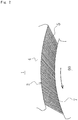
- the multiple bristles 5 mutually fixed at the center in the diameter direction are formed in a planar shape to form planar bristles 10, as shown in FIG. 3 (b) .
- planar bristles 10 are arranged continuously in layers in the circumferential direction to form the circular bristle part 2, as shown in FIG. 3 (c) .
- planar bristles 10 positioned side by side in the circumferential direction may be alternately shifted by one half the diameter of the bristle 5 in the direction of pressure difference and arranged continuously in layers in the circumferential direction, in which case the gaps between planar bristles 10 are reduced and thus the fluid resistance to prevent leakage of the sealed fluid increases.
- the ability of the tips of individual bristles 5 to move independently of the conical vibration of the rotor 60 also helps to reduce wear and improve wear resistance.
- FIG. 4 is a perspective view explaining the process of forming a bristle part pertaining to Embodiment 2 of the present invention.
- Embodiment 2 shown in FIG. 4 is different from Embodiment 1 shown in FIG. 3 in that individual bristles have a square cross-section shape, but since the remainder of the configuration is the same as Embodiment 1, redundant explanations are omitted.
- the ability of the tips of individual bristles 15 to move independently of the conical vibration of the rotor 60 also helps to reduce wear and improve wear resistance.
- FIG. 5 is a drawing explaining another example of how a bristle part pertaining to Embodiment 1 or 2 of the present invention is manufactured.
- bristles 17 that are roughly twice as long as the bristles shown in FIGs. 3 and 4 are arranged in a single row to form a specified width.
- individual bristles 17 may be tentatively fixed to adjacent bristles using adhesive, etc.
- the bristles 17 positioned side by side are fixed by means of welding, fusion, etc., between the longitudinal center 18 and free ends 7, 7 on both sides to form planar bristles 19.
- planar bristles 19 are folded into two at the center 18 being the fulcrum, as shown in FIG. 5 (b) .
- the planar bristle 19 is folded this way, two planar bristles can be formed.
- the folded planar bristles 19 are arranged continuously in layers in the circumferential direction to form the circular bristle part 2, as shown in FIG. 5 (c) .
- the bristle parts 2 can be formed relatively efficiently.
- FIG. 6 is a front view of the brush seal in FIG. 1 with its rotational part eccentrically shifted, as viewed from the high-pressure side.
- the brush seal 1 is such that, as the rotor 60 rotates and contacts the free end 7 of bristles 5, 15 as a result of vibration, shaking, etc., the bristles 5, 15 tilt more while being pressed against the rotor 60.
- degrees of freedom of the tips of bristles 5, 15, or specifically degrees of freedom of the tips of individual bristles 5, 15 in the direction orthogonal to the direction of pressure difference are ensured, their rigidity is low in the direction orthogonal to the direction of pressure difference and therefore the free end 7 can separate from the outer periphery surface of the rotor 60 due to the dynamic pressure of the rotor 60 even when it is rotating at low speed, resulting in such advantages as reduced wear and improved wear resistance.
- the ability of the individual bristles 5, 15 to move independently of the conical vibration of the rotor 60 also helps to reduce wear and improve wear resistance.
- the embodiments explained bristles having a circular or square cross-section shape, but the bristles are not at all restricted to the foregoing and bristles having a polygonal, oval or other cross-section shape can also be used.
- planar bristles where one planar bristle which is twice as long is folded into two at the center representing the fulcrum, to manufacture two planar bristles, for instance, but the manufacturing method is not at all restricted to the foregoing and needless to say planar bristles can also be manufactured by cutting to specified lengths one planar bristle which is twice as long or longer.
- the embodiments explained a case where the bristles positioned side by side are fixed at three locations in the diameter direction between the base end and free end of multiple bristles arranged in a single row, for instance, but the fixed parts are not at all restricted to the foregoing and other variations are also permitted as long as there is at least one fixed location. It is also possible to change the fixed position for each of the planar bristles arranged in the circumferential direction, to prevent fixed positions from concentrating at one location in the diameter direction.
Landscapes
- Engineering & Computer Science (AREA)
- General Engineering & Computer Science (AREA)
- Mechanical Engineering (AREA)
- Sealing Devices (AREA)
- Turbine Rotor Nozzle Sealing (AREA)
Claims (7)
- Bürstendichtung (1) mit einem Borstenteil (2), welcher durch mehrere Borsten (5, 15, 17) gebildet wird, welche an einem stationären Teil (50) zwischen dem stationären Teil (50) und einem rotierenden Teil (60) befestigt sind, welche eine Relativbewegung erfahren, wobei ein Raum dazwischen erhalten bleibt, und
einer hinteren Platte (3), welche benachbart an dem Borstenteil (2) an einer Niedrigdruckseite befestigt ist, um die Bewegung des Borstenteils (2) zu beschränken,
wobei die Bürstendichtung (1) zum Abdichten der Flüssigkeit zwischen dem stationären Teil (50) und dem rotierenden Teil (60), dadurch gekennzeichnet ist, dass der Borstenteil (2), welcher durch mehrere Borsten (5, 15, 17) gebildet wird, so ausgestaltet ist, dass die mehreren Borsten (5, 15, 17), welche in einer Richtung des Druckunterschieds zwischen der Hochdruckseite und der Niedrigdruckseite angeordnet sind, gegenseitig in einer einzelnen Reihe zwischen einem Sockelende (6) und einem freien Ende (7) fixiert sind, um flache Borsten (10, 16, 19) zu bilden, wobei die so gebildeten flachen Borsten (10, 16, 19) dann kontinuierlich in Schichten in einer Umfangsrichtung angeordnet sind, um den Borstenteil (2) zu bilden. - Bürstendichtung (1) nach Anspruch 1, dadurch gekennzeichnet, dass die mehreren Borsten (5, 15, 17), welche in einer Richtung des Druckunterschieds zwischen der Hochdruckseite und der Niedrigdruckseite angeordnet sind, gegenseitig an drei Stellen zwischen dem Sockelende (6) und dem freien Ende (7) fixiert sind, um die flachen Borsten (10, 16, 19) zu bilden.
- Bürstendichtung (1) nach Anspruch 1 oder 2, dadurch gekennzeichnet, dass das Fixieren durch Schweißen erfolgt.
- Bürstendichtung (1) nach einem der Ansprüche 1 bis 3, dadurch gekennzeichnet, dass die mehreren Borsten (5, 15, 17) in einer einzelnen Reihe sind, so dass die mehreren Borsten (5, 15, 17) eine bestimmte Breite in Richtung des Druckunterschieds zwischen der Hochdruckseite und der Niedrigdruckseite bilden, wobei benachbarte Borsten (5) einander berühren und aneinander befestigt sind.
- Bürstendichtung (1) nach einem der Ansprüche 1 bis 4, dadurch gekennzeichnet, dass die Borsten (5, 15, 17) eine kreisförmige Querschnittsform haben.
- Bürstendichtung (1) nach einem der Ansprüche 1 bis 5, dadurch gekennzeichnet, dass die Borsten (5, 15, 17) eine quadratische Querschnittsform haben.
- Bürstendichtung (1) nach einem der Ansprüche 1 bis 6, dadurch gekennzeichnet, dass die flachen Borsten (10, 16, 19) so ausgebildet sind, dass sie in Längsrichtung in einer Mitte gefaltet sind, wobei ein gefalteter Teil das Sockelende (6) und eine Spitze das freie Ende (7) werden.
Applications Claiming Priority (2)
| Application Number | Priority Date | Filing Date | Title |
|---|---|---|---|
| JP2012087998 | 2012-04-08 | ||
| PCT/JP2013/055315 WO2013153866A1 (ja) | 2012-04-08 | 2013-02-28 | ブラシシール |
Publications (3)
| Publication Number | Publication Date |
|---|---|
| EP2837859A1 EP2837859A1 (de) | 2015-02-18 |
| EP2837859A4 EP2837859A4 (de) | 2015-12-02 |
| EP2837859B1 true EP2837859B1 (de) | 2018-05-16 |
Family
ID=49327445
Family Applications (1)
| Application Number | Title | Priority Date | Filing Date |
|---|---|---|---|
| EP13775516.1A Active EP2837859B1 (de) | 2012-04-08 | 2013-02-28 | Bürstendichtung |
Country Status (5)
| Country | Link |
|---|---|
| US (1) | US9598970B2 (de) |
| EP (1) | EP2837859B1 (de) |
| JP (1) | JP5936681B2 (de) |
| CN (1) | CN104114918B (de) |
| WO (1) | WO2013153866A1 (de) |
Families Citing this family (4)
| Publication number | Priority date | Publication date | Assignee | Title |
|---|---|---|---|---|
| CN107965391A (zh) * | 2017-11-23 | 2018-04-27 | 中国航发沈阳黎明航空发动机有限责任公司 | 一种航空发动机静转子间的封严结构 |
| CN109356672B (zh) * | 2018-11-08 | 2023-09-12 | 北京北冶功能材料有限公司 | 一种改善刷丝密封效果的密封结构 |
| CN115013069B (zh) * | 2022-07-06 | 2024-09-27 | 中国航发湖南动力机械研究所 | 涡轮转子冷却系统及航空发动机 |
| US12258866B2 (en) * | 2023-05-29 | 2025-03-25 | Pratt & Whitney Canada Corp. | Seal assembly and method of manufacturing |
Citations (1)
| Publication number | Priority date | Publication date | Assignee | Title |
|---|---|---|---|---|
| US20080224415A1 (en) * | 2007-03-15 | 2008-09-18 | Flaherty Andrew L | Brush Seal Assembly And Method Of Making |
Family Cites Families (23)
| Publication number | Priority date | Publication date | Assignee | Title |
|---|---|---|---|---|
| US3678529A (en) * | 1970-07-06 | 1972-07-25 | John A Woods | Adjustable brush |
| GB2070700B (en) * | 1980-03-01 | 1983-10-05 | Rolls Royce | Gas turbine seals |
| GB8504331D0 (en) * | 1985-02-20 | 1985-03-20 | Rolls Royce | Brush seals |
| US5076590A (en) * | 1990-11-26 | 1991-12-31 | The United States Of America, As Represented By The Administrator Of The National Aeronautics And Space Administration | High temperature, flexible pressure-actuated, brush seal |
| US5474306A (en) * | 1992-11-19 | 1995-12-12 | General Electric Co. | Woven seal and hybrid cloth-brush seals for turbine applications |
| DE69627674T2 (de) * | 1995-10-05 | 2003-10-16 | Eg & G Sealol, Inc. | Bürstendichtung mit einer biegsamen frontscheibe |
| DE19618475B4 (de) * | 1996-05-08 | 2005-10-20 | Mtu Aero Engines Gmbh | Bürstendichtung |
| DE59710884D1 (de) * | 1996-10-02 | 2003-11-27 | Mtu Aero Engines Gmbh | Bürstendichtung |
| US6139018A (en) * | 1998-03-25 | 2000-10-31 | General Electric Co. | Positive pressure-actuated brush seal |
| US6170831B1 (en) | 1998-12-23 | 2001-01-09 | United Technologies Corporation | Axial brush seal for gas turbine engines |
| EP1052438A3 (de) | 1999-05-13 | 2002-02-06 | General Electric Company | Bürstendichtungssegment mit Dämpfung der Borsten |
| JP4157282B2 (ja) * | 2001-06-07 | 2008-10-01 | イーグル・エンジニアリング・エアロスペース株式会社 | ブラシシール装置 |
| JP4689882B2 (ja) | 2001-06-29 | 2011-05-25 | イーグル工業株式会社 | 板ブラシシール装置 |
| JP4751552B2 (ja) * | 2001-09-28 | 2011-08-17 | イーグル工業株式会社 | 板ブラシシールおよび板ブラシシール装置 |
| US20030094848A1 (en) * | 2001-11-20 | 2003-05-22 | Chih-Yuan Shia | Fused filament tuft and fused brush strip |
| JP4054608B2 (ja) * | 2002-05-23 | 2008-02-27 | イーグル工業株式会社 | 板ブラシシール |
| JP4009555B2 (ja) * | 2003-05-20 | 2007-11-14 | イーグル・エンジニアリング・エアロスペース株式会社 | 板ブラシシール装置 |
| DE102004020378A1 (de) * | 2004-04-23 | 2005-11-10 | Alstom Technology Ltd | Lamellendichtung, insbesondere für eine Gasturbine, sowie Verfahren zu deren Herstellung |
| EP1813840A1 (de) * | 2006-01-26 | 2007-08-01 | Siemens Aktiengesellschaft | Mehrstufige Bürstendichtung |
| JP2008121512A (ja) | 2006-11-10 | 2008-05-29 | Mitsubishi Heavy Ind Ltd | ブラシシールおよびこれを用いたタービン |
| CN101476624A (zh) * | 2008-12-11 | 2009-07-08 | 北京中智渝桐节能设备有限公司 | 金属刷式蜂窝密封 |
| US8366115B2 (en) * | 2011-06-30 | 2013-02-05 | United Technologies Corporation | Repairable double sided brush seal |
| US8919633B2 (en) * | 2012-01-04 | 2014-12-30 | General Electric Company | Seal assembly and method for assembling a turbine |
-
2013
- 2013-02-28 CN CN201380009184.1A patent/CN104114918B/zh active Active
- 2013-02-28 JP JP2014510071A patent/JP5936681B2/ja active Active
- 2013-02-28 WO PCT/JP2013/055315 patent/WO2013153866A1/ja not_active Ceased
- 2013-02-28 US US14/380,898 patent/US9598970B2/en active Active
- 2013-02-28 EP EP13775516.1A patent/EP2837859B1/de active Active
Patent Citations (1)
| Publication number | Priority date | Publication date | Assignee | Title |
|---|---|---|---|---|
| US20080224415A1 (en) * | 2007-03-15 | 2008-09-18 | Flaherty Andrew L | Brush Seal Assembly And Method Of Making |
Also Published As
| Publication number | Publication date |
|---|---|
| US9598970B2 (en) | 2017-03-21 |
| JP5936681B2 (ja) | 2016-06-22 |
| EP2837859A1 (de) | 2015-02-18 |
| JPWO2013153866A1 (ja) | 2015-12-17 |
| EP2837859A4 (de) | 2015-12-02 |
| US20150014938A1 (en) | 2015-01-15 |
| WO2013153866A1 (ja) | 2013-10-17 |
| CN104114918B (zh) | 2016-10-26 |
| CN104114918A (zh) | 2014-10-22 |
Similar Documents
| Publication | Publication Date | Title |
|---|---|---|
| JP6254105B2 (ja) | ブラシシール装置 | |
| EP2837860B1 (de) | Bürstendichtung | |
| CN104583651B (zh) | 毛刷密封装置 | |
| JP5178102B2 (ja) | 単一の弾性プレート部材を使用したシャフトシール | |
| EP2837859B1 (de) | Bürstendichtung | |
| US9255486B2 (en) | Rotating brush seal | |
| JP5798413B2 (ja) | コンプライアントプレート部材の振動を減衰させる振動ダンパーを備えたシール組立体 | |
| KR19990037110A (ko) | 회전 기계용의 브러시/래버린스 혼합형 시일 | |
| US20100054924A1 (en) | Brush seal and turbine using the same | |
| KR20140049607A (ko) | 축 시일 장치 및 이것을 구비하는 회전 기계 | |
| JP6012505B2 (ja) | 軸シール装置及び回転機械 | |
| KR20130014584A (ko) | 축 시일 기구 및 이것을 구비한 회전 기계 | |
| EP2837858B1 (de) | Bürstendichtung | |
| JP2009085256A (ja) | 回転流体機械のシール装置 | |
| JP2002364755A (ja) | ブラシシール装置 | |
| JP6759324B2 (ja) | ブラシシール |
Legal Events
| Date | Code | Title | Description |
|---|---|---|---|
| PUAI | Public reference made under article 153(3) epc to a published international application that has entered the european phase |
Free format text: ORIGINAL CODE: 0009012 |
|
| 17P | Request for examination filed |
Effective date: 20140912 |
|
| AK | Designated contracting states |
Kind code of ref document: A1 Designated state(s): AL AT BE BG CH CY CZ DE DK EE ES FI FR GB GR HR HU IE IS IT LI LT LU LV MC MK MT NL NO PL PT RO RS SE SI SK SM TR |
|
| AX | Request for extension of the european patent |
Extension state: BA ME |
|
| DAX | Request for extension of the european patent (deleted) | ||
| RA4 | Supplementary search report drawn up and despatched (corrected) |
Effective date: 20151029 |
|
| RIC1 | Information provided on ipc code assigned before grant |
Ipc: F16J 15/32 20060101ALI20151023BHEP Ipc: F16J 15/22 20060101AFI20151023BHEP |
|
| STAA | Information on the status of an ep patent application or granted ep patent |
Free format text: STATUS: EXAMINATION IS IN PROGRESS |
|
| 17Q | First examination report despatched |
Effective date: 20170130 |
|
| REG | Reference to a national code |
Ref country code: DE Ref legal event code: R079 Ref document number: 602013037569 Country of ref document: DE Free format text: PREVIOUS MAIN CLASS: F16J0015220000 Ipc: F16J0015328800 |
|
| RIC1 | Information provided on ipc code assigned before grant |
Ipc: F16J 15/3292 20160101ALI20171002BHEP Ipc: F16J 15/3288 20160101AFI20171002BHEP |
|
| GRAP | Despatch of communication of intention to grant a patent |
Free format text: ORIGINAL CODE: EPIDOSNIGR1 |
|
| STAA | Information on the status of an ep patent application or granted ep patent |
Free format text: STATUS: GRANT OF PATENT IS INTENDED |
|
| INTG | Intention to grant announced |
Effective date: 20171214 |
|
| RIN1 | Information on inventor provided before grant (corrected) |
Inventor name: INOUE, HIDEYUKI |
|
| GRAS | Grant fee paid |
Free format text: ORIGINAL CODE: EPIDOSNIGR3 |
|
| GRAA | (expected) grant |
Free format text: ORIGINAL CODE: 0009210 |
|
| STAA | Information on the status of an ep patent application or granted ep patent |
Free format text: STATUS: THE PATENT HAS BEEN GRANTED |
|
| AK | Designated contracting states |
Kind code of ref document: B1 Designated state(s): AL AT BE BG CH CY CZ DE DK EE ES FI FR GB GR HR HU IE IS IT LI LT LU LV MC MK MT NL NO PL PT RO RS SE SI SK SM TR |
|
| REG | Reference to a national code |
Ref country code: GB Ref legal event code: FG4D |
|
| REG | Reference to a national code |
Ref country code: CH Ref legal event code: EP |
|
| REG | Reference to a national code |
Ref country code: IE Ref legal event code: FG4D |
|
| REG | Reference to a national code |
Ref country code: DE Ref legal event code: R096 Ref document number: 602013037569 Country of ref document: DE |
|
| REG | Reference to a national code |
Ref country code: AT Ref legal event code: REF Ref document number: 999894 Country of ref document: AT Kind code of ref document: T Effective date: 20180615 |
|
| REG | Reference to a national code |
Ref country code: NL Ref legal event code: MP Effective date: 20180516 |
|
| REG | Reference to a national code |
Ref country code: LT Ref legal event code: MG4D |
|
| PG25 | Lapsed in a contracting state [announced via postgrant information from national office to epo] |
Ref country code: BG Free format text: LAPSE BECAUSE OF FAILURE TO SUBMIT A TRANSLATION OF THE DESCRIPTION OR TO PAY THE FEE WITHIN THE PRESCRIBED TIME-LIMIT Effective date: 20180816 Ref country code: LT Free format text: LAPSE BECAUSE OF FAILURE TO SUBMIT A TRANSLATION OF THE DESCRIPTION OR TO PAY THE FEE WITHIN THE PRESCRIBED TIME-LIMIT Effective date: 20180516 Ref country code: FI Free format text: LAPSE BECAUSE OF FAILURE TO SUBMIT A TRANSLATION OF THE DESCRIPTION OR TO PAY THE FEE WITHIN THE PRESCRIBED TIME-LIMIT Effective date: 20180516 Ref country code: ES Free format text: LAPSE BECAUSE OF FAILURE TO SUBMIT A TRANSLATION OF THE DESCRIPTION OR TO PAY THE FEE WITHIN THE PRESCRIBED TIME-LIMIT Effective date: 20180516 Ref country code: NO Free format text: LAPSE BECAUSE OF FAILURE TO SUBMIT A TRANSLATION OF THE DESCRIPTION OR TO PAY THE FEE WITHIN THE PRESCRIBED TIME-LIMIT Effective date: 20180816 Ref country code: SE Free format text: LAPSE BECAUSE OF FAILURE TO SUBMIT A TRANSLATION OF THE DESCRIPTION OR TO PAY THE FEE WITHIN THE PRESCRIBED TIME-LIMIT Effective date: 20180516 |
|
| PG25 | Lapsed in a contracting state [announced via postgrant information from national office to epo] |
Ref country code: RS Free format text: LAPSE BECAUSE OF FAILURE TO SUBMIT A TRANSLATION OF THE DESCRIPTION OR TO PAY THE FEE WITHIN THE PRESCRIBED TIME-LIMIT Effective date: 20180516 Ref country code: LV Free format text: LAPSE BECAUSE OF FAILURE TO SUBMIT A TRANSLATION OF THE DESCRIPTION OR TO PAY THE FEE WITHIN THE PRESCRIBED TIME-LIMIT Effective date: 20180516 Ref country code: HR Free format text: LAPSE BECAUSE OF FAILURE TO SUBMIT A TRANSLATION OF THE DESCRIPTION OR TO PAY THE FEE WITHIN THE PRESCRIBED TIME-LIMIT Effective date: 20180516 Ref country code: GR Free format text: LAPSE BECAUSE OF FAILURE TO SUBMIT A TRANSLATION OF THE DESCRIPTION OR TO PAY THE FEE WITHIN THE PRESCRIBED TIME-LIMIT Effective date: 20180817 Ref country code: NL Free format text: LAPSE BECAUSE OF FAILURE TO SUBMIT A TRANSLATION OF THE DESCRIPTION OR TO PAY THE FEE WITHIN THE PRESCRIBED TIME-LIMIT Effective date: 20180516 |
|
| REG | Reference to a national code |
Ref country code: CH Ref legal event code: PK Free format text: BERICHTIGUNGEN |
|
| REG | Reference to a national code |
Ref country code: AT Ref legal event code: MK05 Ref document number: 999894 Country of ref document: AT Kind code of ref document: T Effective date: 20180516 |
|
| RIC2 | Information provided on ipc code assigned after grant |
Ipc: F16J 15/3292 20160101ALI20171002BHEP Ipc: F16J 15/3288 20160101AFI20171002BHEP |
|
| PG25 | Lapsed in a contracting state [announced via postgrant information from national office to epo] |
Ref country code: SK Free format text: LAPSE BECAUSE OF FAILURE TO SUBMIT A TRANSLATION OF THE DESCRIPTION OR TO PAY THE FEE WITHIN THE PRESCRIBED TIME-LIMIT Effective date: 20180516 Ref country code: RO Free format text: LAPSE BECAUSE OF FAILURE TO SUBMIT A TRANSLATION OF THE DESCRIPTION OR TO PAY THE FEE WITHIN THE PRESCRIBED TIME-LIMIT Effective date: 20180516 Ref country code: PL Free format text: LAPSE BECAUSE OF FAILURE TO SUBMIT A TRANSLATION OF THE DESCRIPTION OR TO PAY THE FEE WITHIN THE PRESCRIBED TIME-LIMIT Effective date: 20180516 Ref country code: CZ Free format text: LAPSE BECAUSE OF FAILURE TO SUBMIT A TRANSLATION OF THE DESCRIPTION OR TO PAY THE FEE WITHIN THE PRESCRIBED TIME-LIMIT Effective date: 20180516 Ref country code: AT Free format text: LAPSE BECAUSE OF FAILURE TO SUBMIT A TRANSLATION OF THE DESCRIPTION OR TO PAY THE FEE WITHIN THE PRESCRIBED TIME-LIMIT Effective date: 20180516 Ref country code: EE Free format text: LAPSE BECAUSE OF FAILURE TO SUBMIT A TRANSLATION OF THE DESCRIPTION OR TO PAY THE FEE WITHIN THE PRESCRIBED TIME-LIMIT Effective date: 20180516 Ref country code: DK Free format text: LAPSE BECAUSE OF FAILURE TO SUBMIT A TRANSLATION OF THE DESCRIPTION OR TO PAY THE FEE WITHIN THE PRESCRIBED TIME-LIMIT Effective date: 20180516 |
|
| REG | Reference to a national code |
Ref country code: CH Ref legal event code: PK Free format text: BERICHTIGUNGEN |
|
| RIC2 | Information provided on ipc code assigned after grant |
Ipc: F16J 15/3292 20160101ALI20171002BHEP Ipc: F16J 15/3288 20160101AFI20171002BHEP |
|
| REG | Reference to a national code |
Ref country code: DE Ref legal event code: R097 Ref document number: 602013037569 Country of ref document: DE |
|
| PG25 | Lapsed in a contracting state [announced via postgrant information from national office to epo] |
Ref country code: SM Free format text: LAPSE BECAUSE OF FAILURE TO SUBMIT A TRANSLATION OF THE DESCRIPTION OR TO PAY THE FEE WITHIN THE PRESCRIBED TIME-LIMIT Effective date: 20180516 Ref country code: IT Free format text: LAPSE BECAUSE OF FAILURE TO SUBMIT A TRANSLATION OF THE DESCRIPTION OR TO PAY THE FEE WITHIN THE PRESCRIBED TIME-LIMIT Effective date: 20180516 |
|
| PLBE | No opposition filed within time limit |
Free format text: ORIGINAL CODE: 0009261 |
|
| STAA | Information on the status of an ep patent application or granted ep patent |
Free format text: STATUS: NO OPPOSITION FILED WITHIN TIME LIMIT |
|
| 26N | No opposition filed |
Effective date: 20190219 |
|
| PG25 | Lapsed in a contracting state [announced via postgrant information from national office to epo] |
Ref country code: SI Free format text: LAPSE BECAUSE OF FAILURE TO SUBMIT A TRANSLATION OF THE DESCRIPTION OR TO PAY THE FEE WITHIN THE PRESCRIBED TIME-LIMIT Effective date: 20180516 |
|
| REG | Reference to a national code |
Ref country code: CH Ref legal event code: PL |
|
| GBPC | Gb: european patent ceased through non-payment of renewal fee |
Effective date: 20190228 |
|
| PG25 | Lapsed in a contracting state [announced via postgrant information from national office to epo] |
Ref country code: LU Free format text: LAPSE BECAUSE OF NON-PAYMENT OF DUE FEES Effective date: 20190228 Ref country code: MC Free format text: LAPSE BECAUSE OF FAILURE TO SUBMIT A TRANSLATION OF THE DESCRIPTION OR TO PAY THE FEE WITHIN THE PRESCRIBED TIME-LIMIT Effective date: 20180516 |
|
| REG | Reference to a national code |
Ref country code: BE Ref legal event code: MM Effective date: 20190228 |
|
| REG | Reference to a national code |
Ref country code: IE Ref legal event code: MM4A |
|
| PG25 | Lapsed in a contracting state [announced via postgrant information from national office to epo] |
Ref country code: AL Free format text: LAPSE BECAUSE OF FAILURE TO SUBMIT A TRANSLATION OF THE DESCRIPTION OR TO PAY THE FEE WITHIN THE PRESCRIBED TIME-LIMIT Effective date: 20180516 |
|
| PG25 | Lapsed in a contracting state [announced via postgrant information from national office to epo] |
Ref country code: CH Free format text: LAPSE BECAUSE OF NON-PAYMENT OF DUE FEES Effective date: 20190228 Ref country code: LI Free format text: LAPSE BECAUSE OF NON-PAYMENT OF DUE FEES Effective date: 20190228 |
|
| PG25 | Lapsed in a contracting state [announced via postgrant information from national office to epo] |
Ref country code: GB Free format text: LAPSE BECAUSE OF NON-PAYMENT OF DUE FEES Effective date: 20190228 Ref country code: IE Free format text: LAPSE BECAUSE OF NON-PAYMENT OF DUE FEES Effective date: 20190228 |
|
| PG25 | Lapsed in a contracting state [announced via postgrant information from national office to epo] |
Ref country code: FR Free format text: LAPSE BECAUSE OF NON-PAYMENT OF DUE FEES Effective date: 20190228 Ref country code: BE Free format text: LAPSE BECAUSE OF NON-PAYMENT OF DUE FEES Effective date: 20190228 |
|
| PG25 | Lapsed in a contracting state [announced via postgrant information from national office to epo] |
Ref country code: TR Free format text: LAPSE BECAUSE OF FAILURE TO SUBMIT A TRANSLATION OF THE DESCRIPTION OR TO PAY THE FEE WITHIN THE PRESCRIBED TIME-LIMIT Effective date: 20180516 |
|
| PG25 | Lapsed in a contracting state [announced via postgrant information from national office to epo] |
Ref country code: MT Free format text: LAPSE BECAUSE OF NON-PAYMENT OF DUE FEES Effective date: 20190228 Ref country code: PT Free format text: LAPSE BECAUSE OF FAILURE TO SUBMIT A TRANSLATION OF THE DESCRIPTION OR TO PAY THE FEE WITHIN THE PRESCRIBED TIME-LIMIT Effective date: 20180917 |
|
| PG25 | Lapsed in a contracting state [announced via postgrant information from national office to epo] |
Ref country code: CY Free format text: LAPSE BECAUSE OF FAILURE TO SUBMIT A TRANSLATION OF THE DESCRIPTION OR TO PAY THE FEE WITHIN THE PRESCRIBED TIME-LIMIT Effective date: 20180516 |
|
| PG25 | Lapsed in a contracting state [announced via postgrant information from national office to epo] |
Ref country code: IS Free format text: LAPSE BECAUSE OF FAILURE TO SUBMIT A TRANSLATION OF THE DESCRIPTION OR TO PAY THE FEE WITHIN THE PRESCRIBED TIME-LIMIT Effective date: 20180916 |
|
| PG25 | Lapsed in a contracting state [announced via postgrant information from national office to epo] |
Ref country code: HU Free format text: LAPSE BECAUSE OF FAILURE TO SUBMIT A TRANSLATION OF THE DESCRIPTION OR TO PAY THE FEE WITHIN THE PRESCRIBED TIME-LIMIT; INVALID AB INITIO Effective date: 20130228 |
|
| PG25 | Lapsed in a contracting state [announced via postgrant information from national office to epo] |
Ref country code: MK Free format text: LAPSE BECAUSE OF FAILURE TO SUBMIT A TRANSLATION OF THE DESCRIPTION OR TO PAY THE FEE WITHIN THE PRESCRIBED TIME-LIMIT Effective date: 20180516 |
|
| PGFP | Annual fee paid to national office [announced via postgrant information from national office to epo] |
Ref country code: DE Payment date: 20260102 Year of fee payment: 14 |