EP2837863A2 - Structure de soupape - Google Patents
Structure de soupape Download PDFInfo
- Publication number
- EP2837863A2 EP2837863A2 EP14180001.1A EP14180001A EP2837863A2 EP 2837863 A2 EP2837863 A2 EP 2837863A2 EP 14180001 A EP14180001 A EP 14180001A EP 2837863 A2 EP2837863 A2 EP 2837863A2
- Authority
- EP
- European Patent Office
- Prior art keywords
- valve
- discharge port
- blocking portion
- valve body
- plate
- Prior art date
- Legal status (The legal status is an assumption and is not a legal conclusion. Google has not performed a legal analysis and makes no representation as to the accuracy of the status listed.)
- Granted
Links
- 230000000903 blocking effect Effects 0.000 claims abstract description 73
- 239000012530 fluid Substances 0.000 claims description 8
- 238000003825 pressing Methods 0.000 claims description 5
- 230000000149 penetrating effect Effects 0.000 claims description 3
- 238000004519 manufacturing process Methods 0.000 description 7
- 230000003247 decreasing effect Effects 0.000 description 4
- 238000000034 method Methods 0.000 description 3
- 230000002829 reductive effect Effects 0.000 description 3
- 239000000463 material Substances 0.000 description 2
- 239000002184 metal Substances 0.000 description 2
- 238000005192 partition Methods 0.000 description 2
- 230000002441 reversible effect Effects 0.000 description 2
- 208000004210 Pressure Ulcer Diseases 0.000 description 1
- QVGXLLKOCUKJST-UHFFFAOYSA-N atomic oxygen Chemical compound [O] QVGXLLKOCUKJST-UHFFFAOYSA-N 0.000 description 1
- 230000002401 inhibitory effect Effects 0.000 description 1
- 238000003780 insertion Methods 0.000 description 1
- 230000037431 insertion Effects 0.000 description 1
- 229910052760 oxygen Inorganic materials 0.000 description 1
- 239000001301 oxygen Substances 0.000 description 1
- 239000011347 resin Substances 0.000 description 1
- 229920005989 resin Polymers 0.000 description 1
- 238000007789 sealing Methods 0.000 description 1
- 230000001360 synchronised effect Effects 0.000 description 1
- XLYOFNOQVPJJNP-UHFFFAOYSA-N water Substances O XLYOFNOQVPJJNP-UHFFFAOYSA-N 0.000 description 1
Images






Classifications
-
- F—MECHANICAL ENGINEERING; LIGHTING; HEATING; WEAPONS; BLASTING
- F16—ENGINEERING ELEMENTS AND UNITS; GENERAL MEASURES FOR PRODUCING AND MAINTAINING EFFECTIVE FUNCTIONING OF MACHINES OR INSTALLATIONS; THERMAL INSULATION IN GENERAL
- F16K—VALVES; TAPS; COCKS; ACTUATING-FLOATS; DEVICES FOR VENTING OR AERATING
- F16K11/00—Multiple-way valves, e.g. mixing valves; Pipe fittings incorporating such valves
- F16K11/02—Multiple-way valves, e.g. mixing valves; Pipe fittings incorporating such valves with all movable sealing faces moving as one unit
- F16K11/06—Multiple-way valves, e.g. mixing valves; Pipe fittings incorporating such valves with all movable sealing faces moving as one unit comprising only sliding valves, i.e. sliding closure elements
- F16K11/065—Multiple-way valves, e.g. mixing valves; Pipe fittings incorporating such valves with all movable sealing faces moving as one unit comprising only sliding valves, i.e. sliding closure elements with linearly sliding closure members
- F16K11/07—Multiple-way valves, e.g. mixing valves; Pipe fittings incorporating such valves with all movable sealing faces moving as one unit comprising only sliding valves, i.e. sliding closure elements with linearly sliding closure members with cylindrical slides
- F16K11/0716—Multiple-way valves, e.g. mixing valves; Pipe fittings incorporating such valves with all movable sealing faces moving as one unit comprising only sliding valves, i.e. sliding closure elements with linearly sliding closure members with cylindrical slides with fluid passages through the valve member
-
- F—MECHANICAL ENGINEERING; LIGHTING; HEATING; WEAPONS; BLASTING
- F16—ENGINEERING ELEMENTS AND UNITS; GENERAL MEASURES FOR PRODUCING AND MAINTAINING EFFECTIVE FUNCTIONING OF MACHINES OR INSTALLATIONS; THERMAL INSULATION IN GENERAL
- F16K—VALVES; TAPS; COCKS; ACTUATING-FLOATS; DEVICES FOR VENTING OR AERATING
- F16K11/00—Multiple-way valves, e.g. mixing valves; Pipe fittings incorporating such valves
- F16K11/10—Multiple-way valves, e.g. mixing valves; Pipe fittings incorporating such valves with two or more closure members not moving as a unit
- F16K11/20—Multiple-way valves, e.g. mixing valves; Pipe fittings incorporating such valves with two or more closure members not moving as a unit operated by separate actuating members
- F16K11/22—Multiple-way valves, e.g. mixing valves; Pipe fittings incorporating such valves with two or more closure members not moving as a unit operated by separate actuating members with an actuating member for each valve, e.g. interconnected to form multiple-way valves
-
- F—MECHANICAL ENGINEERING; LIGHTING; HEATING; WEAPONS; BLASTING
- F16—ENGINEERING ELEMENTS AND UNITS; GENERAL MEASURES FOR PRODUCING AND MAINTAINING EFFECTIVE FUNCTIONING OF MACHINES OR INSTALLATIONS; THERMAL INSULATION IN GENERAL
- F16K—VALVES; TAPS; COCKS; ACTUATING-FLOATS; DEVICES FOR VENTING OR AERATING
- F16K31/00—Actuating devices; Operating means; Releasing devices
- F16K31/44—Mechanical actuating means
- F16K31/52—Mechanical actuating means with crank, eccentric, or cam
- F16K31/524—Mechanical actuating means with crank, eccentric, or cam with a cam
- F16K31/52408—Mechanical actuating means with crank, eccentric, or cam with a cam comprising a lift valve
- F16K31/52416—Mechanical actuating means with crank, eccentric, or cam with a cam comprising a lift valve comprising a multiple-way lift valve
-
- Y—GENERAL TAGGING OF NEW TECHNOLOGICAL DEVELOPMENTS; GENERAL TAGGING OF CROSS-SECTIONAL TECHNOLOGIES SPANNING OVER SEVERAL SECTIONS OF THE IPC; TECHNICAL SUBJECTS COVERED BY FORMER USPC CROSS-REFERENCE ART COLLECTIONS [XRACs] AND DIGESTS
- Y10—TECHNICAL SUBJECTS COVERED BY FORMER USPC
- Y10T—TECHNICAL SUBJECTS COVERED BY FORMER US CLASSIFICATION
- Y10T137/00—Fluid handling
- Y10T137/8593—Systems
- Y10T137/85978—With pump
- Y10T137/85986—Pumped fluid control
-
- Y—GENERAL TAGGING OF NEW TECHNOLOGICAL DEVELOPMENTS; GENERAL TAGGING OF CROSS-SECTIONAL TECHNOLOGIES SPANNING OVER SEVERAL SECTIONS OF THE IPC; TECHNICAL SUBJECTS COVERED BY FORMER USPC CROSS-REFERENCE ART COLLECTIONS [XRACs] AND DIGESTS
- Y10—TECHNICAL SUBJECTS COVERED BY FORMER USPC
- Y10T—TECHNICAL SUBJECTS COVERED BY FORMER US CLASSIFICATION
- Y10T137/00—Fluid handling
- Y10T137/8593—Systems
- Y10T137/86493—Multi-way valve unit
- Y10T137/86501—Sequential distributor or collector type
Definitions
- the present invention relates to a valve structure for opening and closing a discharge port through which a fluid fed from a pump or the like is discharged, in particular to a valve structure for opening and closing a discharge port by moving a valve body for opening and closing the discharge port in a direction intersecting a drive body by an elastic force of an elastic body and a rotational motion of the drive body, for example, a valve structure in which the elastic body such as spring and the valve body can be integrally formed and which can be used for feeding air into an indoor air mat and a bedsore preventing mat or feeding oxygen into a water tank for aquarium fishes and a septic tank.
- FIG. 12 In order to distribute air supplied from an air pump or the like into a plurality of pipes, for example, a configuration so as to open or close two discharge ports 104a and 104b by subjecting a movable valve 121 connected to a spring 108 and an electromagnetic device 120 such as a solenoid via a piston rod 126 to reciprocating motion by a biasing action of the spring 108 and a driving force of the electromagnetic device 120 has been considered as shown in FIG. 12 . Namely, in FIG. 12 , when an electric current is not fed to the electromagnetic device 120, the movable valve 121 is drawn toward the right side in FIG.
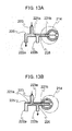
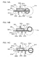
- a piston rod 226 on which a plurality of movable valves 221a - 221e are mounted apart from each other is inserted into a cylinder 225 provided with a suction portion 223 and a plurality of discharge portions 222a - 222c, and by a reciprocating motion of this piston rod 226 in the cylinder 225 by means of a drive source 214, the suction portion 223 is communicated with any of the discharge portions 222a - 222c via a space partitioned by the movable valves 221a - 221e in the cylinder 225 (See, for example, JP 2002-250455 A ).
- FIGS. 13A and 13B represents the case of providing two discharge portions 222a and 222b and FIGS. 14A - 14C represents the case of providing three discharge portions 222a - 222c.
- the suction portion 223 is connected to the cylinder 225 via a branching port 228a or 228b.
- air supplied from an air pump or the like and flowing into the suction portion 223 passes through the space at the left side of the movable valve 221a in the cylinder 225 and is discharged into the discharge portion 222a, and on the other hand, as shown in FIG.
- the discharge portion communicating with the suction portion 223 is changed from the discharge portion 222a to the discharge portion 222b, further to the discharge portion 222c in order according to the positions of the movable valves 221 a - 221e, and the air supplied from an air pump or the like is discharged into any of the discharge portions 222a - 222c communicating with the suction portion 223.
- the present invention was made in light of the above-mentioned situation, and the object of the present invention is to provide a valve structure enabling opening and closing of discharge ports to be controlled by driving two or more valve bodies with one drive source, thus minimizing increase in cost and size resulting from increase in the number of branches.
- a valve structure of the present invention comprises a valve case provided with a suction port into which a fluid flows and discharge ports from which the fluid flows out, valve bodies provided for opening and closing the discharge ports and a drive body provided for driving the valve bodies, wherein the valve bodies are provided with, at one end thereof, a blocking portion disposed so as to face the discharge port for closing the discharge port and at the other end thereof, an elastic member portion which is supported on an inner wall of the valve case facing the discharge port and generates an elastic force for moving the blocking portion so as to open or close the discharge port and the valve body is further provided with a through-hole penetrating the valve body in the direction intersecting the moving direction of the blocking portion moved by the elastic force; the drive body is formed into a rod-like shape having convex portions on its side and is inserted into the through-hole of the valve body; and each of the convex portions is pressed onto the valve body by the rotation of the drive body, thereby moving the blocking portion in the direction intersecting the drive body to control the opening and closing of the discharge port
- the convex portion means a portion protruding outward on the side of the drive body formed in the rod-like shape, and includes both of a protruded portion integrally formed with the drive body and a protruded portion formed separately from the drive body and then mounted on the drive body.
- valve body is provided with the blocking portion and the elastic member portion which are formed integrally since the number of parts can be decreased and the production steps can be simplified, thereby reducing cost.
- the elastic member portion is configured so as to generate an elastic force for moving the blocking portion to close the discharge port, and the blocking portion may be configured so as to separate from the discharge port by pressing the convex portion onto the valve body, thereby opening the discharge port.
- the valve structure may be configured such that a wall surface at least having a portion facing toward the same direction as the moving direction of the blocking portion moved by the elastic force or facing toward a direction at a sharp angle to the moving direction is formed on a part of the valve body, and a plate cam in the form of a plate has a top portion protruding on its outer periphery and the top portion is provided as the convex portion of the drive body and is pressed onto the wall surface at a predetermined rotation angle of the drive body.
- the elastic member portion may be configured such that it includes a pair of plate springs having a cross-section in the doglegged form, and the ends of the pair of plate springs opposite the blocking portion is supported on the inner wall of the valve case.
- the elastic member portion may be configured such that it includes a coil spring, and one end of the coil spring is supported on the inner wall of the valve case and the other end of the coil spring is supported on the other end side of the valve body.
- the valve structure is so configured that the valve body is moved in the direction intersecting the drive body by the rotation of the drive body inserted into the through-hole provided on the valve body, thereby controlling the opening and closing of the discharge port, and therefore, when one drive body is inserted into the through-holes of a plurality of valve bodies, only by rotating the drive body, for example, the plurality of discharge ports arranged in the direction along the drive body can be opened and closed. Accordingly, only with one driving source and yet a driving source such as a relatively inexpensive motor without using an expensive electromagnetic device, the plurality of discharge ports can be brought to a closed or opened state. Thus, since no separate driving sources are needed for each of the valve bodies, when comparing a cost for the case of providing valve bodies for the respective discharge ports, the cost can be reduced as compared with a prior art.
- a branched structure can be configured according to the number of branches by increasing only the number of valve bodies and convex portions to be provided on the drive body without providing the same number of driving sources as the number of branches or without providing branched ports at the suction side, thereby enabling the number of branches to be increased while inhibiting increase in cost and size.
- the blocking portion for closing the discharge port and the elastic member portion for example, a spring for generating an elastic force and thereby moving the blocking portion are provided on the valve body, and therefore, it is not necessary to assemble the both via the discharge port, and production can be carried out easily at low cost. Further, by integrally forming the blocking portion and the elastic member portion, the number of parts can be decreased and the production steps can be simplified, resulting in further reduced cost.
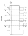
- the valve structure according to this embodiment is configured so as to comprise a valve case 2 provided with a suction port 3 into which a fluid flows and discharge ports 4a - 4d from which the fluid flows out, valve bodies 5a - 5d provided for opening and closing the discharge ports 4a - 4d and a cam shaft 6 which is a drive body provided for driving the valve bodies 5a - 5d.
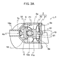
- the valve body 5a is provided with a blocking portion 7a disposed opposite to the discharge port 4a for closing the discharge port 4a at one end on the left-hand side in FIG.
- a pair of plate springs 8a which is an elastic member portion generating an elastic force for moving the blocking portion 7a for opening or closing the discharge port 4a and is provided at the other end on the right-hand side in FIG. 3A .
- End portions 81 of the pair of plate springs 8a located opposite to the blocking portion 7a are supported by the inner wall of the valve case 2 facing the discharge port 4a.
- a through-hole 9 penetrating the valve body 5a in a direction (of arrangement of the plurality of valve bodies 5a - 5d and) intersecting the moving direction (the direction shown by an arrow P1 in FIG. 3A ) of the blocking portion 7a moved by the elastic force of the plate springs 8a is provided.
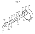
- a cam shaft 6 formed into a rod-like shape is provided with a plate cam 10a, and a top portion 11 a of the plate cam 10a forms a convex portion on the side of the cam shaft 6.
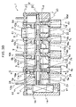
- the cam shaft 6 is inserted into the through-holes of the four valve bodies 5a - 5d.
- the opening and the closing of the four discharge ports 4a - 4d are controlled by pressing the top portions 11a - 11d of the plate cams 10a to 10d onto the valve bodies 5a - 5d by rotating the cam shaft 6 and thus moving the blocking portions 7a - 7d in the direction intersecting the cam shaft 6.
- the four discharge ports 4a - 4d are provided, and the corresponding four each of the valve bodies 5a - 5d and the plate cams 10a - 10d are provided.
- the number of them is not limited to four, and may be one or plurality other than four.
- the valve case 2 is formed by combining a first housing 21 and a second housing 22.
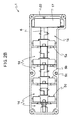
- the first housing 21 is provided with the suction port 3 communicating with an air path 14 which is an inner space of the second housing 22 shown in FIGS. 2A and 2B , and in this embodiment, in the second housing 22, four discharge pipes 16a - 16d are arranged in a row and the discharge pipes 16a - 16d are communicated with the air path 14 via the discharge ports 4a - 4d. Air from the suction port 3 circulates in the air path 14 and is discharged from any of the discharge ports 4a - 4d which is not closed by the blocking portions 7a - 7d of the valve bodies 5a - 5d.
- the suction port 3 may be connected to, for example, an air pump via an air supply pipe, and the discharge ports 4a - 4d may be connected to, for example, a plurality of septic tanks via the discharge pipes 16a - 16d, respectively.
- the material of the valve case 2 is not limited particularly, and metal, plastic or the like may be used therefor.
- the four valve bodies 5a - 5d, the cam shaft 6 inserted into the through-holes 9 of these four valve bodies 5a - 5d and the drive source 17 being connected to the cam shaft 6 and driving the rotation of the cam shaft 6 are disposed in the air path 14.
- the valve bodies 5a - 5d are designed so that the vertical direction thereof is guided by the guide portions 18 and 19 along the moving direction P1 of the valve bodies 5a - 5d as shown in FIG. 3A , and the axial direction of the cam shaft 6 (a thickness direction of a plate-like main body portion 23 explained later) is guided by the guiding portions 20 as shown in FIG. 3B .
- the blocking portions 7a - 7d provided at one end each of the valve bodies 5a - 5d are located so as to face the discharge ports 4a - 4d, respectively.
- the plate springs 8a - 8d provided at the other end side of the valve bodies 5a - 5d are disposed so that when the first housing 21 is combined with the second housing 22, the end portions 81 opposite to the blocking portions 7a - 7d are pressed onto the inner wall of the first housing 21 and are in a compressed state. Therefore, the plate springs 8a - 8d always generate an elastic force for returning to an equilibrium state and are always biasing the blocking portions 7a - 7d toward the discharge ports 4a - 4d side.
- FIG. 3A shows that the valve body 5a is pressed toward the righthand direction in FIG. 3A by means of the top portion 11 a of the plate cam 10a, the plate spring 8a is further compressed and the discharge port 4a is in an opened state.
- valve bodies 5a - 5d are disposed in a position where at least a part of wall surfaces 12a - 12d provided on the valve bodies 5a - 5d face the four plate cams 10a - 10d provided on the cam shaft 6 in the axial direction of the cam shaft 6 and at a part of a circumferential direction of the cam shaft 6.
- FIG. 3B shows that the top portion 11a of only the plate cam 10a located at the leftmost side is in a state of being pressed onto the wall surface 12a provided on the valve body 5a. Therefore, in FIG.
- FIG. 3B only the discharge port 4a located opposite to the blocking portion 7a provided on the valve body 5a is in an opened state, and the other discharge ports 4b - 4d are in a closed state.
- the top portion 11c of the plate cam 10c combined with the valve body 5c is shown in a state of facing the discharge port 4c side, and the top portions of the plate cams 10b and 10d face in a vertical direction with respect to the cross-section shown in FIG. 3B , and therefore are not shown.
- FIGS. 4A - 4D represent outlines of the front view, left side view, rear view and plan view of the valve body 5 of one embodiment of the present invention.
- the valve body 5 is provided with a plate-like main body portion 23, the blocking portion 7 formed into a disk-like shape and provided at one end of the main body portion 23 and the pair of plate springs 8 at the other end of the main body portion 23.
- the main body portion 23 is provided with a through-hole 9 for inserting the cam shaft 6 thereinto.
- the through-hole 9 is formed into a long hole at least having a length for a stroke of the valve body 5 along the moving direction of the valve body 5 at around the center of the main body portion 23 so that the valve body 5 can move regarding the cam shaft 6 in the direction intersecting the axial direction of the cam shaft 6.
- the respective one ends of the pair of plate springs 8 are jointed to the end of the plate-like main body portion 23 at the other end side, and the main body portion 23 and the blocking portion 7 are connected by means of a connection portion 24 having a width nearly equal to the thickness of the main body portion 23.
- a groove 25 for fitting an O-ring thereto is provided on the side periphery of the blocking portion 7, a groove 25 for fitting an O-ring thereto is provided.
- a guided portion 26 which is guided by the guide portions 19 of the first housing 21 (See FIG. 3A ) and protrudes toward the moving direction of the valve body 5 from the other end side of the main body portion 23 is provided.
- the plate springs 8 are formed so as to have a cross-section in the doglegged form as if a rectangular thin plate is bent around the center in its lengthwise direction.
- the thickness of the plate spring 8 and the shape of the bent portion thereof are not limited particularly, and it is preferable that the bent portion is formed at a curvature radius of 2 to 5 mm at an angle of 30° to 50° in a state of a force not being applied to the plate springs 8 since the discharge ports 4a - 4d can be properly opened or closed by the blocking portion 7 of the valve body 5.
- Each one end of the plate springs 8 is jointed to ends 27 of the upper and lower two sides at the other end side of the main body portion 23 in FIG. 4A .
- a thick portion 28 for forming a wall surface 12 onto which the top portions 11a - 11d of the plate cams 10a - 10d are pressed is formed between the end of the other end side and the periphery of the through-hole 9 at the other end side.
- the thick portion 28 protrudes toward the axial direction of the cam shaft 6 from the surface of the thin plate-like main body portion 23 and is formed thick.
- the thick portion 28 is formed such that the wall surface 12 at least has a portion directed toward the same direction as the moving direction of the biased blocking portion 7 or directed toward a direction at a sharp angle to this moving direction so that when the thick portion 28 is pressed by the top portions 11a - 11d of the plate cams 10a - 10d, the blocking portion 7 is moved in the direction reverse to the moving direction of the blocking portion 7 biased by the elastic force generated by the plate spring 8.
- the through-hole 9 is formed into the long hole, but is not limited to this shape as far as it has a shape and size being sufficient for enabling a drive body such as the cam shaft 6 to be inserted thereinto. Further, in this embodiment, the through-hole 9 is formed so as to penetrate the main body portion 23 in the direction being orthogonal to the flat plane of the thin plate-like main body portion 23, but this embodiment is not limited to this, and the through-hole 9 may be formed so as to penetrate the main body portion 23 in the direction intersecting the moving direction of the blocking portion 7 moved by the elastic force generated by the plate spring 8.
- the valve body 5 may be formed by forming the blocking portion 7 and the plate springs 8 separately and then combining them.
- the material of the valve body 5 is not limited particularly as far as a sealing property of the blocking portion 7 and a desired elasticity of the plate springs 8 can be obtained, and metal, a resin such as a plastic and a combination thereof can be used.
- kind of the elastic member of the elastic member portion is not limited particularly as far as it can bias the blocking portion 7 of the valve body 5 toward the discharge ports 4a - 4d.
- coil spring 91 may be used as the elastic member portion.
- One end of the coil spring 91 is supported on the inner wall of the valve case, and the other end thereof is supported on the other end side of the valve body 5.
- the coil spring 91 and the valve body 5 may be formed integrally, or may be formed as separate members.
- the coil spring 91 is, as shown in FIGS. 10 and 11 , arranged around the guided portion 26 formed at the other end side of the valve body 5.
- valve body 5a is pressed toward the right direction in FIG. 11 by the top portion 11 a of the plate cam 10a, the coil spring is further compressed and the discharge port 4a is in an opened state.
- the configuration of the valve body 5 and the valve case 2 may be the same as that in the case of using the plate spring 8.
- the coil spring 91 shown in the drawings are provided at the other end side of the valve body 5, but its position is not limited particularly as far as it can bias the blocking portion 7 of the valve body 5 toward the discharge ports 4a - 4d. The same thing can be said also with respect to the case of using the plate spring 8.
- FIGS. 5A and 5B show a cross-sectional view of C-C line of FIG. 1A .
- FIG. 5A shows the discharge port 4a being in a closed state
- FIG. 5B shows the discharge port 4a being in an opened state. The position of the C-C cross-section of FIG.
- the plate springs 8a are designed so as to be normally in the compressed state and always generate an elastic force for returning to an equilibrium state. Therefore, as shown in FIG. 5A , when in FIG. 5A , the top portion 11 a of the plate cam 10a faces toward the direction such as the upward, downward, or left direction as in FIG.
- the blocking portion 7a is biased toward the side shown by an arrow P1 in FIG. 5A , namely toward the discharge port 4a side, thereby closing the discharge port 4a.
- the cam shaft 6 is driven for rotation by the drive source 17 (See FIG. 3B ) to bring the valve to the state shown in FIG. 5B , namely to such a state that the top portion 11a of the plate cam 10a faces toward the right direction in FIG. 5B , the top portion 11a of the plate cam 10a is pressed onto the wall surface 12a provided on the valve body 5a, thereby moving the blocking portion 7a in the direction intersecting the cam shaft 6, i.e.
- the discharge port 4a can be in an opened state or in a closed state by reciprocating motion of the blocking portion 7a in the direction intersecting the cam shaft 6 which is performed by an action of the elastic force generated by the plate spring 8a and an action of pressing the top portion 11a of the plate cam 10a onto the valve body 5a by the rotation of the cam shaft 6.
- this embodiment is configured such that the blocking portion 7 is biased with the elastic force of the plate spring 8, thereby closing the discharge port 4, and the valve body 5 is moved toward the direction reverse to the direction of the elastic force of the plate spring 8 by means of the driving force of the drive source 17, thereby opening the discharge port 4.
- the present invention is not limited to such a configuration.
- Example of other configuration of the valve body 5 of this embodiment is explained below by referring to FIGS. 6A and 6B.
- FIGS. 6A and 6B show the cross-section of the C-C line of FIG. 1A .
- FIG. 6A shows the discharge port 4a being in an opened state
- FIG. 6B shows the discharge port 4a being in a closed state. Also in FIGS.
- the profiles of the main body portion 23 and the connection portion 24 of the valve body 5a are represented by the two-dot chain lines in the same manner as in FIGS. 5A and 5B .
- the thick portion 28 forming the wall surface 12a is provided in a region of the valve body 5a located near the blocking portion 7a side rather than the cam shaft 6 inserted into the valve body 5a.
- the end portions 81 of the pair of plate springs 8a located opposite to the blocking portion 7a are inserted between the inner wall of the first housing 21 and hook portion 29 having an L-shape in its cross section and being located on the inner wall of the first housing 21, thereby restricting the movement of the whole plate spring 8a toward the blocking portion 7a side.
- the shape of the plate spring 8a and the dimensions of other parts of the valve body 5a are designed so that in a state that the top portion 11 a of the plate cam 10a is not pressed onto the wall surface 12a provided on the valve body 5a as shown in FIG. 6A , the plate spring 8a is in an equilibrium state so as not to be compressed or expanded and the discharge port 4a is in an opened state.
- the blocking portion 7a is separated from the discharge port 4a by the elastic force of the plate spring 8a acting in a compressing direction, the discharge port 4a is returned to the opened state and the plate spring 8a also returns to the equilibrium state.
- the cam shaft 6 is formed into a rod-like shape, and in this embodiment, the four plate cams 10a - 10d are provided apart from each other at the same pitch as that of the discharge ports 4a - 4d (See FIG. 3B ).
- the plate cams 10a - 10d are formed into a plate-like shape having the top portions 11a -11d, respectively which are protruding on a part of the outer periphery thereof, and thus the convex portions are formed on the side of the cam shaft 6 by the top portions 11a - 11d of the plate cams 10a - 10d.
- the drive source 17 is not limited particularly as long as the cam shaft 6 can be rotated, and in order to secure a predetermined opening time of the discharge ports 4a - 4d, a synchronous motor rotating at a low speed and a pulse motor rotating by a predetermined angle for each one pulse of electric power to be supplied in the form of pulse are preferred.
- the cam shaft 6 is composed of a plurality of shaft parts 61 and is formed by connecting the separate shaft parts 61 formed integrally with the respective plate cams 10a - 10d in its axial direction.
- the plate cams 10 can be increased only by further connecting additional shaft parts 61 according to the increased number of branches without producing a new cam shaft 6.
- the method of fixing the connection portion of the shaft part 61 is not limited particularly, and the shaft part 61 may be fixed by caulking, screwing or the like, or the shaft parts 61 may be inserted simply in order in the axial direction without fixing them and as shown in FIG.
- the end shaft part 61 may be provided close to the inner wall of the valve case 2, thereby preventing each shaft part 61 from falling during the use thereof.
- a method being capable of separating the shaft parts 61, when the number of branches is decreased, excess shaft parts 61 can be removed and the length of the cam shaft 6 can be shortened without producing a new cam shaft 6.
- such a method is preferable because when any of the valve bodies 5a - 5d are broken, even in the case where the through-holes 9 of the valve bodies 5a - 5d do not have a shape or size being capable of passing the plate cams 10a - 10d thereinto, the broken valve bodies 5a - 5d can be replaced by separating the shaft parts 61.
- the entire cam shaft 6 may be formed integrally, and also, the respective plate cams 10a - 10d may be formed separately from the cam shaft 6 and the shaft parts 61 and then assembled with the cam shaft 6 or the shaft parts 61.
- the plate cams 10a - 10d are arranged so that the respective top portions 11a - 11d face toward different directions in the circumferential direction of the cam shaft 6 (different directions by an angle of every 90° in this embodiment).
- a plurality of the discharge ports 4a - 4d arranged in a row on one surface of the second housing 22 can be brought to an opened state separately at different time mutually by rotating the cam shaft 6.
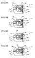
- switching of the discharge ports 4a - 4d to an opened or closed state is then explained referring to FIGS. 8A - 8D and FIGS. 9A - 9D .
- FIGS. 8A - 8D represent C-C cross-section, D-D cross section, E-E cross section and F-F cross section, respectively of FIG. 1A .
- FIGS. 8A - 8D show that the discharge port 4a locating on the C-C cross section of FIG. 1A is opened and the other discharge ports 4b - 4d are in a closed state. Namely, as shown in FIG. 8A , the top portion 11a of the plate cam 10a is directed toward the wall surface 12a side of the valve body 5a at the right side on FIG. 8A , the valve body 5a is pressed toward the opposite side of the discharge port 4a, the blocking portion 7a is separated from the discharge port 4a, and thus the discharge port 4a is in an opened state.
- the top portions 11b - 11d of the plate cams 10b - 10d shown in FIGS. 8B - 8D are directed toward the lower side, left side and upper side, respectively on FIGS. 8B - 8D , the valve bodies 5b - 5d are not pressed by the plate cams 10b - 10d, and the blocking portions 7b - 7d are biased by the elastic force generated by the plate springs 8b - 8d to close the discharge ports 4b - 4d.
- FIGS. 9A - 9D show the state of the cam shaft 6 of FIGS. 8A - 8D having been rotated counter-clockwise by an angle of 90° each, and FIGS. 9A - 9D represent C-C cross-section, D-D cross section, E-E cross section and F-F cross section, respectively of FIG. 1A in the same manner as in FIGS. 8A - 8D .
- FIGS. 9A - 9D In the state shown in FIGS. 9A - 9D , the top portion 11b of the plate cam 10b shown in FIG.
- FIGS. 9A, 9C and 9D are directed toward the upper side, lower side and left side, respectively on FIGS.
- valve bodies 5a, 5c and 5d are not pressed by the plate cams 10a, 10c and 10d, and the blocking portions 7a, 7c and 7d are biased by the elastic force generated by the plate springs 8a, 8c and 8d to close the discharge ports 4a, 4c and 4d.
- the plate cams 10a - 10d are arranged so that the directions of the respective top portions 11a - 11d differ by an angle of every 90° in the circumferential direction of the cam shaft 6.
- the arrangement of the plate cams is not limited to such configuration, and the angle may be one other than 90° or a part or the whole of the top portions 11a - 11d of the plate cams 10a - 10d may be configured so as to be directed in the same direction.
- the multi-directional selector valve using the valve structure of this embodiment can be produced easily.
- one shaft part 61 is mounted on the drive source 17, and this shaft part 61 is inserted into the through-hole 9 of the valve body 5a.
- connection of the shaft parts 61 to be added with the inserted shaft part and insertion of the connected shaft parts 61 into the valve bodies 5b - 5d are repeated alternately.
- the connected set of the assembled shaft parts 61, namely the cam shaft 6 and the valve bodies 5a - 5d as well as the drive source 17 are set on the second housing 22 while guiding the peripheries of the valve bodies 5a - 5d by means of the guide portions 18 (See FIG. 3A ) and the guide portions 20 (See FIG.
- the multi-directional selector valve using the valve structure of this embodiment can be completed.
- the plate springs 8a - 8d are compressed, thereby generating the elastic force which biases the blocking portions 7a - 7d continually toward the discharge ports 4a - 4d side to enable the discharge ports 4a - 4d to be in a closed state.
- the blocking portion for closing the discharge port is provided at one end of the valve body, the elastic member portion which generates an elastic force for moving the blocking portion is provided at the other end thereof, and further, the drive body having a convex portion on its side is inserted into the through-hole provided on the valve body in the direction intersecting the direction of movement of the blocking portion moved by the elastic force of the elastic member portion. Therefore, the blocking portion can undergoes a reciprocating motion in the direction intersecting the drive body by an action caused by the elastic force generated by the elastic member portion and an action of the convex portion for pressing the valve body by the rotation of the drive body.
- plural blocking portions can be moved only by one drive source, and for example, plural discharge ports arranged along the drive body can be in an opened or closed state.
- the cost for providing the valve bodies for the respective discharge ports can be reduced more as compared with that of prior art.
- a fluid can be distributed to many discharge ports by increasing the number of valve bodies and convex portions provided on the drive body without incurring increase in cost and size.
- the valve can be produced at low cost, and further cost reduction can be achieved by integrally forming the blocking portion and the elastic member portion for decrease in the number of parts and simplification of production steps.
Landscapes
- Engineering & Computer Science (AREA)
- General Engineering & Computer Science (AREA)
- Mechanical Engineering (AREA)
- Multiple-Way Valves (AREA)
- Mechanically-Actuated Valves (AREA)
- Valve Device For Special Equipments (AREA)
Applications Claiming Priority (2)
| Application Number | Priority Date | Filing Date | Title |
|---|---|---|---|
| JP2013167788 | 2013-08-12 | ||
| JP2014150953A JP2015057563A (ja) | 2013-08-12 | 2014-07-24 | 弁構造 |
Publications (3)
| Publication Number | Publication Date |
|---|---|
| EP2837863A2 true EP2837863A2 (fr) | 2015-02-18 |
| EP2837863A3 EP2837863A3 (fr) | 2015-03-04 |
| EP2837863B1 EP2837863B1 (fr) | 2017-10-25 |
Family
ID=51292830
Family Applications (1)
| Application Number | Title | Priority Date | Filing Date |
|---|---|---|---|
| EP14180001.1A Not-in-force EP2837863B1 (fr) | 2013-08-12 | 2014-08-06 | Structure de soupape |
Country Status (4)
| Country | Link |
|---|---|
| US (1) | US9644754B2 (fr) |
| EP (1) | EP2837863B1 (fr) |
| JP (1) | JP2015057563A (fr) |
| CN (1) | CN104373635B (fr) |
Families Citing this family (12)
| Publication number | Priority date | Publication date | Assignee | Title |
|---|---|---|---|---|
| JP6570221B2 (ja) * | 2013-08-12 | 2019-09-04 | 株式会社テクノ高槻 | 多方向切替バルブ |
| CN209977340U (zh) * | 2019-04-16 | 2020-01-21 | 明达实业(厦门)有限公司 | 泳池水处理设备的多路阀结构 |
| US11523657B2 (en) | 2019-05-20 | 2022-12-13 | Nike, Inc. | Foot support systems including fluid movement controllers |
| EP3789645A1 (fr) * | 2019-09-03 | 2021-03-10 | HUSCO Automotive Holdings LLC | Systèmes et procédés pour un ensemble soupape-champignon |
| CN115388209A (zh) * | 2021-05-24 | 2022-11-25 | 青岛海尔滚筒洗衣机有限公司 | 一种控制阀结构及投放装置 |
| CN115387089B (zh) * | 2021-05-24 | 2025-11-25 | 青岛海尔滚筒洗衣机有限公司 | 一种切换器及投放装置 |
| CN115387086B (zh) * | 2021-05-24 | 2025-11-28 | 佛山海尔滚筒洗衣机有限公司 | 一种切换器及投放装置 |
| EP4350183A4 (fr) * | 2021-05-24 | 2024-09-25 | Qingdao Haier Drum Washing Machine Co., Ltd. | Structure de soupape de commande, commutateur et dispositif de distribution |
| CN115387088A (zh) * | 2021-05-24 | 2022-11-25 | 青岛海尔滚筒洗衣机有限公司 | 一种切换器及投放装置及衣物处理设备 |
| WO2023023277A1 (fr) * | 2021-08-18 | 2023-02-23 | Husco Automotive Holdings Llc | Ensemble soupape à tige et soupape de commande à came avec ensemble soupape à tige |
| CN113578581B (zh) * | 2021-09-30 | 2021-12-10 | 江苏信美医学工程科技有限公司 | 一种医疗器械用的防锈剂喷涂装置 |
| CN114542752B (zh) * | 2022-02-08 | 2025-07-22 | 深圳市汉石新能源热管理技术有限公司 | 一种多通道流量分配模块 |
Citations (2)
| Publication number | Priority date | Publication date | Assignee | Title |
|---|---|---|---|---|
| JP2001193663A (ja) | 1999-12-28 | 2001-07-17 | Hitachi Chem Co Ltd | エアーポンプ及び該エアーポンプを有した汚水浄化槽 |
| JP2002250455A (ja) | 2001-02-20 | 2002-09-06 | Techno Takatsuki Co Ltd | 多方向性切替バルブ |
Family Cites Families (14)
| Publication number | Priority date | Publication date | Assignee | Title |
|---|---|---|---|---|
| US2291564A (en) * | 1940-05-23 | 1942-07-28 | American Throttle Company Inc | Method of assembling cam followers and valve stems |
| US2297576A (en) * | 1940-09-11 | 1942-09-29 | Glenn L Martin Co | Valve |
| US2533652A (en) * | 1947-02-05 | 1950-12-12 | Cass Products Company | Valve |
| US3756559A (en) * | 1970-09-23 | 1973-09-04 | Food Research & Equipment Co | Solenoid-operated valve |
| US3680830A (en) * | 1971-01-05 | 1972-08-01 | Nasa | Evacuation valve |
| JPH0792164B2 (ja) * | 1986-04-18 | 1995-10-09 | 山田 満江 | 流動制御機器 |
| US4846138A (en) * | 1986-07-28 | 1989-07-11 | Alto Automotive, Inc. | Low profile internal combustion engine |
| CN2230845Y (zh) * | 1994-08-27 | 1996-07-10 | 李毅 | 流体助关控制阀 |
| US6454243B2 (en) * | 2000-02-14 | 2002-09-24 | The Meyer Company | Springless seat cup |
| US6247493B1 (en) * | 2000-03-09 | 2001-06-19 | Richard C. Henderson | Miniature pulsatile flow controller |
| JP3597453B2 (ja) * | 2000-09-22 | 2004-12-08 | 株式会社市丸技研 | 直動形電動バルブ |
| JP3972112B1 (ja) * | 2007-01-22 | 2007-09-05 | テクノエクセル株式会社 | 水道蛇口直結型浄水器 |
| JP2009014020A (ja) * | 2007-06-29 | 2009-01-22 | Inax Corp | パイロット式流調弁装置 |
| ITMO20130032A1 (it) * | 2013-02-12 | 2014-08-13 | Polmac S R L | Rubinetto dosatore per il travaso di liquidi ad incrementata praticita' di impiego. |
-
2014
- 2014-07-24 JP JP2014150953A patent/JP2015057563A/ja active Pending
- 2014-08-06 EP EP14180001.1A patent/EP2837863B1/fr not_active Not-in-force
- 2014-08-11 US US14/456,034 patent/US9644754B2/en not_active Expired - Fee Related
- 2014-08-12 CN CN201410395186.5A patent/CN104373635B/zh not_active Expired - Fee Related
Patent Citations (2)
| Publication number | Priority date | Publication date | Assignee | Title |
|---|---|---|---|---|
| JP2001193663A (ja) | 1999-12-28 | 2001-07-17 | Hitachi Chem Co Ltd | エアーポンプ及び該エアーポンプを有した汚水浄化槽 |
| JP2002250455A (ja) | 2001-02-20 | 2002-09-06 | Techno Takatsuki Co Ltd | 多方向性切替バルブ |
Also Published As
| Publication number | Publication date |
|---|---|
| CN104373635A (zh) | 2015-02-25 |
| EP2837863A3 (fr) | 2015-03-04 |
| HK1206806A1 (en) | 2016-01-15 |
| EP2837863B1 (fr) | 2017-10-25 |
| CN104373635B (zh) | 2018-09-04 |
| US9644754B2 (en) | 2017-05-09 |
| US20150041006A1 (en) | 2015-02-12 |
| JP2015057563A (ja) | 2015-03-26 |
Similar Documents
| Publication | Publication Date | Title |
|---|---|---|
| EP2837863B1 (fr) | Structure de soupape | |
| EP2837864B1 (fr) | Soupape de sélecteur multidirectionnel | |
| CN101479473B (zh) | 具有防气蚀损伤部件的进口节流控制的液泵 | |
| CN201943954U (zh) | 多气缸旋转式压缩机及冷冻循环装置 | |
| US20120063924A1 (en) | Reciprocating fluid pumps including magnets, devices including magnets for use with reciprocating fluid pumps, and related methods | |
| KR102267569B1 (ko) | 왕복동 펌프 | |
| US9482360B2 (en) | Miniature high performance solenoid valve | |
| JP2005180332A (ja) | プランジャポンプ及びエンジン用流体ポンプ | |
| KR101182610B1 (ko) | 솔레노이드 펌프 및 이를 포함한 액추에이터 | |
| KR20150064376A (ko) | 피스톤 유체펌프 | |
| CN1932352A (zh) | 流路切换阀 | |
| TWI761810B (zh) | 含有磁鐵之往復式流體泵及相關總成、系統與方法 | |
| US4886429A (en) | Electromagnetic pump | |
| JP5209672B2 (ja) | 電磁往復動流体装置 | |
| HK1206806B (en) | Valve structure | |
| US9746004B2 (en) | Pulse controlled linear actuator | |
| EP2827032B1 (fr) | Vanne à solénoïde haute performance miniature | |
| RU2622217C1 (ru) | Перистальтический насос | |
| JP5653285B2 (ja) | 容積型ポンプ | |
| JP2015222107A (ja) | デテント部材を備えた弁装置 | |
| JP2024134043A (ja) | バルブ装置 | |
| JP2018053864A (ja) | ガスポンプ | |
| KR20160097889A (ko) | 비접촉식 다이아프램 펌프 | |
| CN107035588B (zh) | 燃料泵 | |
| CN105940230A (zh) | 线性致动器 |
Legal Events
| Date | Code | Title | Description |
|---|---|---|---|
| PUAL | Search report despatched |
Free format text: ORIGINAL CODE: 0009013 |
|
| 17P | Request for examination filed |
Effective date: 20140806 |
|
| AK | Designated contracting states |
Kind code of ref document: A2 Designated state(s): AL AT BE BG CH CY CZ DE DK EE ES FI FR GB GR HR HU IE IS IT LI LT LU LV MC MK MT NL NO PL PT RO RS SE SI SK SM TR |
|
| AX | Request for extension of the european patent |
Extension state: BA ME |
|
| PUAI | Public reference made under article 153(3) epc to a published international application that has entered the european phase |
Free format text: ORIGINAL CODE: 0009012 |
|
| AK | Designated contracting states |
Kind code of ref document: A3 Designated state(s): AL AT BE BG CH CY CZ DE DK EE ES FI FR GB GR HR HU IE IS IT LI LT LU LV MC MK MT NL NO PL PT RO RS SE SI SK SM TR |
|
| AX | Request for extension of the european patent |
Extension state: BA ME |
|
| RIC1 | Information provided on ipc code assigned before grant |
Ipc: F16K 11/22 20060101ALI20150128BHEP Ipc: F16K 31/524 20060101AFI20150128BHEP |
|
| R17P | Request for examination filed (corrected) |
Effective date: 20150813 |
|
| RBV | Designated contracting states (corrected) |
Designated state(s): AL AT BE BG CH CY CZ DE DK EE ES FI FR GB GR HR HU IE IS IT LI LT LU LV MC MK MT NL NO PL PT RO RS SE SI SK SM TR |
|
| GRAP | Despatch of communication of intention to grant a patent |
Free format text: ORIGINAL CODE: EPIDOSNIGR1 |
|
| STAA | Information on the status of an ep patent application or granted ep patent |
Free format text: STATUS: GRANT OF PATENT IS INTENDED |
|
| INTG | Intention to grant announced |
Effective date: 20170515 |
|
| RIN1 | Information on inventor provided before grant (corrected) |
Inventor name: MORISHITA, TOMOYUKI Inventor name: KAWASAKI, NOZOMU |
|
| GRAS | Grant fee paid |
Free format text: ORIGINAL CODE: EPIDOSNIGR3 |
|
| GRAA | (expected) grant |
Free format text: ORIGINAL CODE: 0009210 |
|
| STAA | Information on the status of an ep patent application or granted ep patent |
Free format text: STATUS: THE PATENT HAS BEEN GRANTED |
|
| AK | Designated contracting states |
Kind code of ref document: B1 Designated state(s): AL AT BE BG CH CY CZ DE DK EE ES FI FR GB GR HR HU IE IS IT LI LT LU LV MC MK MT NL NO PL PT RO RS SE SI SK SM TR |
|
| REG | Reference to a national code |
Ref country code: GB Ref legal event code: FG4D |
|
| REG | Reference to a national code |
Ref country code: CH Ref legal event code: EP |
|
| REG | Reference to a national code |
Ref country code: AT Ref legal event code: REF Ref document number: 940265 Country of ref document: AT Kind code of ref document: T Effective date: 20171115 |
|
| REG | Reference to a national code |
Ref country code: IE Ref legal event code: FG4D |
|
| REG | Reference to a national code |
Ref country code: DE Ref legal event code: R096 Ref document number: 602014016190 Country of ref document: DE |
|
| REG | Reference to a national code |
Ref country code: NL Ref legal event code: MP Effective date: 20171025 |
|
| REG | Reference to a national code |
Ref country code: LT Ref legal event code: MG4D |
|
| REG | Reference to a national code |
Ref country code: AT Ref legal event code: MK05 Ref document number: 940265 Country of ref document: AT Kind code of ref document: T Effective date: 20171025 |
|
| PG25 | Lapsed in a contracting state [announced via postgrant information from national office to epo] |
Ref country code: NL Free format text: LAPSE BECAUSE OF FAILURE TO SUBMIT A TRANSLATION OF THE DESCRIPTION OR TO PAY THE FEE WITHIN THE PRESCRIBED TIME-LIMIT Effective date: 20171025 |
|
| PG25 | Lapsed in a contracting state [announced via postgrant information from national office to epo] |
Ref country code: ES Free format text: LAPSE BECAUSE OF FAILURE TO SUBMIT A TRANSLATION OF THE DESCRIPTION OR TO PAY THE FEE WITHIN THE PRESCRIBED TIME-LIMIT Effective date: 20171025 Ref country code: FI Free format text: LAPSE BECAUSE OF FAILURE TO SUBMIT A TRANSLATION OF THE DESCRIPTION OR TO PAY THE FEE WITHIN THE PRESCRIBED TIME-LIMIT Effective date: 20171025 Ref country code: NO Free format text: LAPSE BECAUSE OF FAILURE TO SUBMIT A TRANSLATION OF THE DESCRIPTION OR TO PAY THE FEE WITHIN THE PRESCRIBED TIME-LIMIT Effective date: 20180125 Ref country code: LT Free format text: LAPSE BECAUSE OF FAILURE TO SUBMIT A TRANSLATION OF THE DESCRIPTION OR TO PAY THE FEE WITHIN THE PRESCRIBED TIME-LIMIT Effective date: 20171025 Ref country code: SE Free format text: LAPSE BECAUSE OF FAILURE TO SUBMIT A TRANSLATION OF THE DESCRIPTION OR TO PAY THE FEE WITHIN THE PRESCRIBED TIME-LIMIT Effective date: 20171025 |
|
| PG25 | Lapsed in a contracting state [announced via postgrant information from national office to epo] |
Ref country code: GR Free format text: LAPSE BECAUSE OF FAILURE TO SUBMIT A TRANSLATION OF THE DESCRIPTION OR TO PAY THE FEE WITHIN THE PRESCRIBED TIME-LIMIT Effective date: 20180126 Ref country code: BG Free format text: LAPSE BECAUSE OF FAILURE TO SUBMIT A TRANSLATION OF THE DESCRIPTION OR TO PAY THE FEE WITHIN THE PRESCRIBED TIME-LIMIT Effective date: 20180125 Ref country code: RS Free format text: LAPSE BECAUSE OF FAILURE TO SUBMIT A TRANSLATION OF THE DESCRIPTION OR TO PAY THE FEE WITHIN THE PRESCRIBED TIME-LIMIT Effective date: 20171025 Ref country code: IS Free format text: LAPSE BECAUSE OF FAILURE TO SUBMIT A TRANSLATION OF THE DESCRIPTION OR TO PAY THE FEE WITHIN THE PRESCRIBED TIME-LIMIT Effective date: 20180225 Ref country code: LV Free format text: LAPSE BECAUSE OF FAILURE TO SUBMIT A TRANSLATION OF THE DESCRIPTION OR TO PAY THE FEE WITHIN THE PRESCRIBED TIME-LIMIT Effective date: 20171025 Ref country code: AT Free format text: LAPSE BECAUSE OF FAILURE TO SUBMIT A TRANSLATION OF THE DESCRIPTION OR TO PAY THE FEE WITHIN THE PRESCRIBED TIME-LIMIT Effective date: 20171025 Ref country code: HR Free format text: LAPSE BECAUSE OF FAILURE TO SUBMIT A TRANSLATION OF THE DESCRIPTION OR TO PAY THE FEE WITHIN THE PRESCRIBED TIME-LIMIT Effective date: 20171025 |
|
| REG | Reference to a national code |
Ref country code: DE Ref legal event code: R097 Ref document number: 602014016190 Country of ref document: DE |
|
| PG25 | Lapsed in a contracting state [announced via postgrant information from national office to epo] |
Ref country code: DK Free format text: LAPSE BECAUSE OF FAILURE TO SUBMIT A TRANSLATION OF THE DESCRIPTION OR TO PAY THE FEE WITHIN THE PRESCRIBED TIME-LIMIT Effective date: 20171025 Ref country code: CY Free format text: LAPSE BECAUSE OF FAILURE TO SUBMIT A TRANSLATION OF THE DESCRIPTION OR TO PAY THE FEE WITHIN THE PRESCRIBED TIME-LIMIT Effective date: 20171025 Ref country code: EE Free format text: LAPSE BECAUSE OF FAILURE TO SUBMIT A TRANSLATION OF THE DESCRIPTION OR TO PAY THE FEE WITHIN THE PRESCRIBED TIME-LIMIT Effective date: 20171025 Ref country code: SK Free format text: LAPSE BECAUSE OF FAILURE TO SUBMIT A TRANSLATION OF THE DESCRIPTION OR TO PAY THE FEE WITHIN THE PRESCRIBED TIME-LIMIT Effective date: 20171025 |
|
| REG | Reference to a national code |
Ref country code: FR Ref legal event code: PLFP Year of fee payment: 5 |
|
| PG25 | Lapsed in a contracting state [announced via postgrant information from national office to epo] |
Ref country code: RO Free format text: LAPSE BECAUSE OF FAILURE TO SUBMIT A TRANSLATION OF THE DESCRIPTION OR TO PAY THE FEE WITHIN THE PRESCRIBED TIME-LIMIT Effective date: 20171025 Ref country code: IT Free format text: LAPSE BECAUSE OF FAILURE TO SUBMIT A TRANSLATION OF THE DESCRIPTION OR TO PAY THE FEE WITHIN THE PRESCRIBED TIME-LIMIT Effective date: 20171025 Ref country code: SM Free format text: LAPSE BECAUSE OF FAILURE TO SUBMIT A TRANSLATION OF THE DESCRIPTION OR TO PAY THE FEE WITHIN THE PRESCRIBED TIME-LIMIT Effective date: 20171025 Ref country code: PL Free format text: LAPSE BECAUSE OF FAILURE TO SUBMIT A TRANSLATION OF THE DESCRIPTION OR TO PAY THE FEE WITHIN THE PRESCRIBED TIME-LIMIT Effective date: 20171025 |
|
| PLBE | No opposition filed within time limit |
Free format text: ORIGINAL CODE: 0009261 |
|
| STAA | Information on the status of an ep patent application or granted ep patent |
Free format text: STATUS: NO OPPOSITION FILED WITHIN TIME LIMIT |
|
| 26N | No opposition filed |
Effective date: 20180726 |
|
| PG25 | Lapsed in a contracting state [announced via postgrant information from national office to epo] |
Ref country code: SI Free format text: LAPSE BECAUSE OF FAILURE TO SUBMIT A TRANSLATION OF THE DESCRIPTION OR TO PAY THE FEE WITHIN THE PRESCRIBED TIME-LIMIT Effective date: 20171025 |
|
| PG25 | Lapsed in a contracting state [announced via postgrant information from national office to epo] |
Ref country code: MC Free format text: LAPSE BECAUSE OF FAILURE TO SUBMIT A TRANSLATION OF THE DESCRIPTION OR TO PAY THE FEE WITHIN THE PRESCRIBED TIME-LIMIT Effective date: 20171025 |
|
| REG | Reference to a national code |
Ref country code: CH Ref legal event code: PL |
|
| GBPC | Gb: european patent ceased through non-payment of renewal fee |
Effective date: 20180806 |
|
| PG25 | Lapsed in a contracting state [announced via postgrant information from national office to epo] |
Ref country code: LI Free format text: LAPSE BECAUSE OF NON-PAYMENT OF DUE FEES Effective date: 20180831 Ref country code: CH Free format text: LAPSE BECAUSE OF NON-PAYMENT OF DUE FEES Effective date: 20180831 Ref country code: LU Free format text: LAPSE BECAUSE OF NON-PAYMENT OF DUE FEES Effective date: 20180806 |
|
| REG | Reference to a national code |
Ref country code: IE Ref legal event code: MM4A |
|
| PG25 | Lapsed in a contracting state [announced via postgrant information from national office to epo] |
Ref country code: IE Free format text: LAPSE BECAUSE OF NON-PAYMENT OF DUE FEES Effective date: 20180806 |
|
| PG25 | Lapsed in a contracting state [announced via postgrant information from national office to epo] |
Ref country code: GB Free format text: LAPSE BECAUSE OF NON-PAYMENT OF DUE FEES Effective date: 20180806 |
|
| PG25 | Lapsed in a contracting state [announced via postgrant information from national office to epo] |
Ref country code: MT Free format text: LAPSE BECAUSE OF NON-PAYMENT OF DUE FEES Effective date: 20180806 |
|
| PG25 | Lapsed in a contracting state [announced via postgrant information from national office to epo] |
Ref country code: TR Free format text: LAPSE BECAUSE OF FAILURE TO SUBMIT A TRANSLATION OF THE DESCRIPTION OR TO PAY THE FEE WITHIN THE PRESCRIBED TIME-LIMIT Effective date: 20171025 |
|
| PG25 | Lapsed in a contracting state [announced via postgrant information from national office to epo] |
Ref country code: PT Free format text: LAPSE BECAUSE OF FAILURE TO SUBMIT A TRANSLATION OF THE DESCRIPTION OR TO PAY THE FEE WITHIN THE PRESCRIBED TIME-LIMIT Effective date: 20171025 Ref country code: HU Free format text: LAPSE BECAUSE OF FAILURE TO SUBMIT A TRANSLATION OF THE DESCRIPTION OR TO PAY THE FEE WITHIN THE PRESCRIBED TIME-LIMIT; INVALID AB INITIO Effective date: 20140806 |
|
| PG25 | Lapsed in a contracting state [announced via postgrant information from national office to epo] |
Ref country code: MK Free format text: LAPSE BECAUSE OF NON-PAYMENT OF DUE FEES Effective date: 20171025 |
|
| PG25 | Lapsed in a contracting state [announced via postgrant information from national office to epo] |
Ref country code: AL Free format text: LAPSE BECAUSE OF FAILURE TO SUBMIT A TRANSLATION OF THE DESCRIPTION OR TO PAY THE FEE WITHIN THE PRESCRIBED TIME-LIMIT Effective date: 20171025 |
|
| PGFP | Annual fee paid to national office [announced via postgrant information from national office to epo] |
Ref country code: DE Payment date: 20220831 Year of fee payment: 9 Ref country code: CZ Payment date: 20220802 Year of fee payment: 9 |
|
| PGFP | Annual fee paid to national office [announced via postgrant information from national office to epo] |
Ref country code: FR Payment date: 20220829 Year of fee payment: 9 Ref country code: BE Payment date: 20220810 Year of fee payment: 9 |
|
| REG | Reference to a national code |
Ref country code: DE Ref legal event code: R119 Ref document number: 602014016190 Country of ref document: DE |
|
| PG25 | Lapsed in a contracting state [announced via postgrant information from national office to epo] |
Ref country code: CZ Free format text: LAPSE BECAUSE OF NON-PAYMENT OF DUE FEES Effective date: 20230806 |
|
| REG | Reference to a national code |
Ref country code: BE Ref legal event code: MM Effective date: 20230831 |
|
| PG25 | Lapsed in a contracting state [announced via postgrant information from national office to epo] |
Ref country code: FR Free format text: LAPSE BECAUSE OF NON-PAYMENT OF DUE FEES Effective date: 20230831 Ref country code: DE Free format text: LAPSE BECAUSE OF NON-PAYMENT OF DUE FEES Effective date: 20240301 |
|
| PG25 | Lapsed in a contracting state [announced via postgrant information from national office to epo] |
Ref country code: BE Free format text: LAPSE BECAUSE OF NON-PAYMENT OF DUE FEES Effective date: 20230831 |