EP2838177A1 - Energieverwaltungsvorrichtung und energieverwaltungssystem - Google Patents
Energieverwaltungsvorrichtung und energieverwaltungssystem Download PDFInfo
- Publication number
- EP2838177A1 EP2838177A1 EP13775242.4A EP13775242A EP2838177A1 EP 2838177 A1 EP2838177 A1 EP 2838177A1 EP 13775242 A EP13775242 A EP 13775242A EP 2838177 A1 EP2838177 A1 EP 2838177A1
- Authority
- EP
- European Patent Office
- Prior art keywords
- reduction
- electric power
- energy management
- consumed
- load
- Prior art date
- Legal status (The legal status is an assumption and is not a legal conclusion. Google has not performed a legal analysis and makes no representation as to the accuracy of the status listed.)
- Ceased
Links
Images


Classifications
-
- G—PHYSICS
- G05—CONTROLLING; REGULATING
- G05B—CONTROL OR REGULATING SYSTEMS IN GENERAL; FUNCTIONAL ELEMENTS OF SUCH SYSTEMS; MONITORING OR TESTING ARRANGEMENTS FOR SUCH SYSTEMS OR ELEMENTS
- G05B15/00—Systems controlled by a computer
- G05B15/02—Systems controlled by a computer electric
-
- G—PHYSICS
- G06—COMPUTING OR CALCULATING; COUNTING
- G06Q—INFORMATION AND COMMUNICATION TECHNOLOGY [ICT] SPECIALLY ADAPTED FOR ADMINISTRATIVE, COMMERCIAL, FINANCIAL, MANAGERIAL OR SUPERVISORY PURPOSES; SYSTEMS OR METHODS SPECIALLY ADAPTED FOR ADMINISTRATIVE, COMMERCIAL, FINANCIAL, MANAGERIAL OR SUPERVISORY PURPOSES, NOT OTHERWISE PROVIDED FOR
- G06Q50/00—Information and communication technology [ICT] specially adapted for implementation of business processes of specific business sectors, e.g. utilities or tourism
- G06Q50/06—Energy or water supply
-
- H—ELECTRICITY
- H02—GENERATION; CONVERSION OR DISTRIBUTION OF ELECTRIC POWER
- H02J—ELECTRIC POWER NETWORKS; CIRCUIT ARRANGEMENTS OR SYSTEMS FOR SUPPLYING OR DISTRIBUTING ELECTRIC POWER; SYSTEMS FOR STORING ELECTRIC ENERGY
- H02J13/00—Circuit arrangements for providing remote monitoring or remote control of equipment in a power distribution network
- H02J13/12—Monitoring network conditions, e.g. electrical magnitudes or operational status
-
- H—ELECTRICITY
- H02—GENERATION; CONVERSION OR DISTRIBUTION OF ELECTRIC POWER
- H02J—ELECTRIC POWER NETWORKS; CIRCUIT ARRANGEMENTS OR SYSTEMS FOR SUPPLYING OR DISTRIBUTING ELECTRIC POWER; SYSTEMS FOR STORING ELECTRIC ENERGY
- H02J13/00—Circuit arrangements for providing remote monitoring or remote control of equipment in a power distribution network
- H02J13/14—Circuit arrangements for providing remote monitoring or remote control of equipment in a power distribution network the power network being locally controlled, e.g. home energy management systems [HEMS]
-
- H—ELECTRICITY
- H02—GENERATION; CONVERSION OR DISTRIBUTION OF ELECTRIC POWER
- H02J—ELECTRIC POWER NETWORKS; CIRCUIT ARRANGEMENTS OR SYSTEMS FOR SUPPLYING OR DISTRIBUTING ELECTRIC POWER; SYSTEMS FOR STORING ELECTRIC ENERGY
- H02J3/00—Circuit arrangements for AC mains or AC distribution networks
- H02J3/12—Arrangements for adjusting voltage in AC networks by changing a characteristic of the network load
- H02J3/14—Arrangements for adjusting voltage in AC networks by changing a characteristic of the network load by switching loads on to, or off from, the networks, e.g. progressively balanced loading
-
- H—ELECTRICITY
- H02—GENERATION; CONVERSION OR DISTRIBUTION OF ELECTRIC POWER
- H02J—ELECTRIC POWER NETWORKS; CIRCUIT ARRANGEMENTS OR SYSTEMS FOR SUPPLYING OR DISTRIBUTING ELECTRIC POWER; SYSTEMS FOR STORING ELECTRIC ENERGY
- H02J3/00—Circuit arrangements for AC mains or AC distribution networks
- H02J3/17—Demand-responsive operation of AC power transmission or distribution networks
-
- G—PHYSICS
- G05—CONTROLLING; REGULATING
- G05B—CONTROL OR REGULATING SYSTEMS IN GENERAL; FUNCTIONAL ELEMENTS OF SUCH SYSTEMS; MONITORING OR TESTING ARRANGEMENTS FOR SUCH SYSTEMS OR ELEMENTS
- G05B2219/00—Program-control systems
- G05B2219/20—Pc systems
- G05B2219/26—Pc applications
- G05B2219/2642—Domotique, domestic, home control, automation, smart house
-
- H—ELECTRICITY
- H02—GENERATION; CONVERSION OR DISTRIBUTION OF ELECTRIC POWER
- H02J—ELECTRIC POWER NETWORKS; CIRCUIT ARRANGEMENTS OR SYSTEMS FOR SUPPLYING OR DISTRIBUTING ELECTRIC POWER; SYSTEMS FOR STORING ELECTRIC ENERGY
- H02J2105/00—Networks for supplying or distributing electric power characterised by their spatial reach or by the load
- H02J2105/40—Networks for supplying or distributing electric power characterised by their spatial reach or by the load characterised by the loads connecting to the networks or being supplied by the networks
- H02J2105/42—Home appliances
-
- H—ELECTRICITY
- H02—GENERATION; CONVERSION OR DISTRIBUTION OF ELECTRIC POWER
- H02J—ELECTRIC POWER NETWORKS; CIRCUIT ARRANGEMENTS OR SYSTEMS FOR SUPPLYING OR DISTRIBUTING ELECTRIC POWER; SYSTEMS FOR STORING ELECTRIC ENERGY
- H02J2105/00—Networks for supplying or distributing electric power characterised by their spatial reach or by the load
- H02J2105/50—Networks for supplying or distributing electric power characterised by their spatial reach or by the load for selectively controlling the operation of the loads
- H02J2105/52—Networks for supplying or distributing electric power characterised by their spatial reach or by the load for selectively controlling the operation of the loads for limitation of the power consumption in the networks or in one section of the networks, e.g. load shedding or peak shaving
-
- Y—GENERAL TAGGING OF NEW TECHNOLOGICAL DEVELOPMENTS; GENERAL TAGGING OF CROSS-SECTIONAL TECHNOLOGIES SPANNING OVER SEVERAL SECTIONS OF THE IPC; TECHNICAL SUBJECTS COVERED BY FORMER USPC CROSS-REFERENCE ART COLLECTIONS [XRACs] AND DIGESTS
- Y02—TECHNOLOGIES OR APPLICATIONS FOR MITIGATION OR ADAPTATION AGAINST CLIMATE CHANGE
- Y02B—CLIMATE CHANGE MITIGATION TECHNOLOGIES RELATED TO BUILDINGS, e.g. HOUSING, HOUSE APPLIANCES OR RELATED END-USER APPLICATIONS
- Y02B70/00—Technologies for an efficient end-user side electric power management and consumption
- Y02B70/30—Systems integrating technologies related to power network operation and communication or information technologies for improving the carbon footprint of the management of residential or tertiary loads, i.e. smart grids as climate change mitigation technology in the buildings sector, including also the last stages of power distribution and the control, monitoring or operating management systems at local level
-
- Y—GENERAL TAGGING OF NEW TECHNOLOGICAL DEVELOPMENTS; GENERAL TAGGING OF CROSS-SECTIONAL TECHNOLOGIES SPANNING OVER SEVERAL SECTIONS OF THE IPC; TECHNICAL SUBJECTS COVERED BY FORMER USPC CROSS-REFERENCE ART COLLECTIONS [XRACs] AND DIGESTS
- Y02—TECHNOLOGIES OR APPLICATIONS FOR MITIGATION OR ADAPTATION AGAINST CLIMATE CHANGE
- Y02B—CLIMATE CHANGE MITIGATION TECHNOLOGIES RELATED TO BUILDINGS, e.g. HOUSING, HOUSE APPLIANCES OR RELATED END-USER APPLICATIONS
- Y02B70/00—Technologies for an efficient end-user side electric power management and consumption
- Y02B70/30—Systems integrating technologies related to power network operation and communication or information technologies for improving the carbon footprint of the management of residential or tertiary loads, i.e. smart grids as climate change mitigation technology in the buildings sector, including also the last stages of power distribution and the control, monitoring or operating management systems at local level
- Y02B70/3225—Demand response systems, e.g. load shedding, peak shaving
-
- Y—GENERAL TAGGING OF NEW TECHNOLOGICAL DEVELOPMENTS; GENERAL TAGGING OF CROSS-SECTIONAL TECHNOLOGIES SPANNING OVER SEVERAL SECTIONS OF THE IPC; TECHNICAL SUBJECTS COVERED BY FORMER USPC CROSS-REFERENCE ART COLLECTIONS [XRACs] AND DIGESTS
- Y02—TECHNOLOGIES OR APPLICATIONS FOR MITIGATION OR ADAPTATION AGAINST CLIMATE CHANGE
- Y02B—CLIMATE CHANGE MITIGATION TECHNOLOGIES RELATED TO BUILDINGS, e.g. HOUSING, HOUSE APPLIANCES OR RELATED END-USER APPLICATIONS
- Y02B90/00—Enabling technologies or technologies with a potential or indirect contribution to GHG emissions mitigation
- Y02B90/20—Smart grids as enabling technology in buildings sector
-
- Y—GENERAL TAGGING OF NEW TECHNOLOGICAL DEVELOPMENTS; GENERAL TAGGING OF CROSS-SECTIONAL TECHNOLOGIES SPANNING OVER SEVERAL SECTIONS OF THE IPC; TECHNICAL SUBJECTS COVERED BY FORMER USPC CROSS-REFERENCE ART COLLECTIONS [XRACs] AND DIGESTS
- Y04—INFORMATION OR COMMUNICATION TECHNOLOGIES HAVING AN IMPACT ON OTHER TECHNOLOGY AREAS
- Y04S—SYSTEMS INTEGRATING TECHNOLOGIES RELATED TO POWER NETWORK OPERATION, COMMUNICATION OR INFORMATION TECHNOLOGIES FOR IMPROVING THE ELECTRICAL POWER GENERATION, TRANSMISSION, DISTRIBUTION, MANAGEMENT OR USAGE, i.e. SMART GRIDS
- Y04S20/00—Management or operation of end-user stationary applications or the last stages of power distribution; Controlling, monitoring or operating thereof
-
- Y—GENERAL TAGGING OF NEW TECHNOLOGICAL DEVELOPMENTS; GENERAL TAGGING OF CROSS-SECTIONAL TECHNOLOGIES SPANNING OVER SEVERAL SECTIONS OF THE IPC; TECHNICAL SUBJECTS COVERED BY FORMER USPC CROSS-REFERENCE ART COLLECTIONS [XRACs] AND DIGESTS
- Y04—INFORMATION OR COMMUNICATION TECHNOLOGIES HAVING AN IMPACT ON OTHER TECHNOLOGY AREAS
- Y04S—SYSTEMS INTEGRATING TECHNOLOGIES RELATED TO POWER NETWORK OPERATION, COMMUNICATION OR INFORMATION TECHNOLOGIES FOR IMPROVING THE ELECTRICAL POWER GENERATION, TRANSMISSION, DISTRIBUTION, MANAGEMENT OR USAGE, i.e. SMART GRIDS
- Y04S20/00—Management or operation of end-user stationary applications or the last stages of power distribution; Controlling, monitoring or operating thereof
- Y04S20/20—End-user application control systems
- Y04S20/222—Demand response systems, e.g. load shedding, peak shaving
-
- Y—GENERAL TAGGING OF NEW TECHNOLOGICAL DEVELOPMENTS; GENERAL TAGGING OF CROSS-SECTIONAL TECHNOLOGIES SPANNING OVER SEVERAL SECTIONS OF THE IPC; TECHNICAL SUBJECTS COVERED BY FORMER USPC CROSS-REFERENCE ART COLLECTIONS [XRACs] AND DIGESTS
- Y04—INFORMATION OR COMMUNICATION TECHNOLOGIES HAVING AN IMPACT ON OTHER TECHNOLOGY AREAS
- Y04S—SYSTEMS INTEGRATING TECHNOLOGIES RELATED TO POWER NETWORK OPERATION, COMMUNICATION OR INFORMATION TECHNOLOGIES FOR IMPROVING THE ELECTRICAL POWER GENERATION, TRANSMISSION, DISTRIBUTION, MANAGEMENT OR USAGE, i.e. SMART GRIDS
- Y04S20/00—Management or operation of end-user stationary applications or the last stages of power distribution; Controlling, monitoring or operating thereof
- Y04S20/20—End-user application control systems
- Y04S20/242—Home appliances
Definitions
- the invention relates to an energy management device and an energy management system, which are used to limit an amount of electric power to be consumed in a power consumer's facility.
- the above-mentioned document discloses a control device (DSM (Demand Side Management) control device) that is connected to a home network to which load apparatuses (facility apparatuses) are connected.
- the control device is configured to control each load apparatus through receiving a DSM command of directing a limitation of power consumption from a DSM command center managed by an electric power company.
- the control device is configured to obtain, via the home network, a current value or an electric power amount detected by a current sensor attached to a distribution board.
- the DSM command is provided as an upper limit of consumption current for each prescribed time zone for example.
- the control device is configured to reduce an operation capacity of each load apparatus or stop the operation thereof so that the detected current value does not exceed the upper limit provided in the DSM command.
- the control device is configured to control each load apparatus so as to optimally achieve the DSM command according to the condition of each load apparatus.
- the following methods are considered for limiting the amount of electric power to be consumed in the consumer's facility: a method of stopping operation of the load apparatus or reducing the operation capacity thereof; and a method of limiting an operating time period of the load apparatus.
- the most desirable method among the methods changes depending on an actual way of using the load apparatus.
- ways of using load apparatuses are not uniform, and the ways are different depending on the load apparatuses. Also, the ways are different depending on users.
- a load apparatus is only controlled according to the condition of the load apparatus for a demand request (the DSM command), and accordingly, information other than the condition of the load apparatus (that is, a way of using the load apparatus, as described above) is not reflected in the control of the load apparatus.
- the control device in the above document may not give a user satisfaction regarding the operation (control) for limiting the amount of electric power to be consumed in the consumer's facility.
- an electric power company may make the following request: "we ask for your cooperation in saving an electric power amount of 10% or more between 9 a.m. and 9 p.m. on weekdays from March 1 to May 31".
- An energy management device includes an acquisition part, a request input part, a method storage part, an execution part, and a selection part.
- the acquisition part is configured to acquire, from a measuring device, measured values, as respective power consumption amounts corresponding to branch circuits or load apparatuses in a consumer's facility.
- the request input part is configured to receive a reduction request for requesting a reduction in an amount of electric power to be consumed in the consumer's facility.
- the method storage part is configured to store reduction methods for reducing amounts of electric powers to be consumed in the branch circuits or the load apparatuses. The reduction methods are made to correspond to the branch circuits or the load apparatuses individually.
- the execution part is configured to execute, in response to the reduction request, at least one of presentation of the reduction methods stored in the method storage part, and control of the branch circuits or the load apparatuses according to the reduction methods.
- the selection part is configured to make a user select, from a plurality of predetermined reduction methods, the reduction methods to be stored in the method storage part and made to correspond to the branch circuits or the load apparatuses individually.
- the energy management device preferably further includes a history storage part configured to store history data of the respective power consumption amounts corresponding to the branch circuits or the load apparatuses.
- the execution part is preferably configured to, when the reduction methods selected by the user are stored in the method storage part, as a trigger, determine respective setting values corresponding to the branch circuits or the load apparatuses so as to achieve the reduction request, with the history data stored in the history storage part, as a reference value.
- the selection part is preferably configured to present the setting values to the user.
- the reduction request includes at least information related to an object time zone in which the reduction in electric power to be consumed is requested.
- the execution part is preferably configured to extract, from the history storage part, the history data in a time zone that agrees with the object time zone, and determine the setting values with the extracted history data as the reference value.
- the plurality of predetermined reduction methods includes a method of shifting a timing, at which electric power is consumed by a corresponding branch circuit or load apparatus, from a time zone, in which the reduction in electric power to be consumed is requested in the reduction request, to another time zone.
- the plurality of predetermined reduction methods includes a method of setting an upper limit to a length of a time period during which electric power is consumed by a corresponding branch circuit or load apparatus.
- the plurality of predetermined reduction methods includes a method of setting an upper limit to an amount of electric power to be consumed by a corresponding branch circuit or load apparatus.
- the plurality of predetermined reduction methods includes a method of limiting an operation mode of a corresponding load apparatus.
- An energy management system includes: a measuring device to be attached to a distribution board installed in a consumer's facility, or load apparatuses to be used in the consumer's facility, to measure an amount of electric power; and the above-mentioned energy management device.
- the selection part is configured to make a user select, from the plurality of predetermined reduction methods, the reduction methods to be stored in the method storage part and made to correspond to the branch circuits or the load apparatuses individually, and therefore, it is possible to easily give the user satisfaction regarding an operation for limiting an amount of electric power to be consumed in the consumer's facility.
- an energy management system is used for a general detached house as a power consumer's facility. However, it is not limited to such a detached house.
- the energy management system may be used for a dwelling unit of an apartment house, an office, a shop or the like. In any cases, if a consumer is conscious of a reduction in an amount of electric power to be consumed, it is possible to limit the amount by introducing the energy management system described below.
- a distribution board 2 is disposed, and a power line L1 and plural power lines L2 are connected to this distribution board 2.
- the power line L1 is for supplying electric power received from a power supply system 3 as a commercial power supply
- the plural power lines L2 are for supplying the electric power to load apparatuses 4 disposed in the house.
- illustration of the load apparatuses 4 connected to the plural power lines L2 is omitted.
- a single load apparatus 4 in Fig. 2 is actually connected to the distribution board 2 via a power line L2.
- An energy management system includes: a measuring device 5 that is attached to the distribution board 2 and configured to measure respective power consumption amounts corresponding to branch circuits or the load apparatuses 4; and an energy management device 1 for acquiring, as measured values, the respective power consumption amounts measured by the measuring device 5.
- the energy management device 1 is further configured to be capable of communicating with a host device 6 via a communication network NT as the Internet.
- the host device 6 may be a computer server for example, and may be managed (operated) by an electric power company that generates and supplies electric power, or a service provider that manages the electric power instead of the electric power company.
- the host device 6 has a function of reporting, to the energy management device 1, a reduction request for requesting a reduction in an amount of electric power to be consumed in the consumer's house, in response to a condition of electric power supplied from the electric power company.
- the reduction request mentioned here may include, for example, a request: "we ask for your cooperation in saving an electric power amount of 10% or more between 9 a.m. and 9 p.m. on weekdays from March 1 to May 31" from the electric power company.
- the distribution board 2 includes: a main breaker 21 that is connected to the power line L1 for supplying the electric power received from the power supply system 3; and plural branch breakers 22 that are connected to a secondary side of the main breaker 21 via a conductor L3.
- the load apparatuses 4 (not shown in Fig. 3 ) are connected to secondary sides of the branch breakers 22 via the plural power lines L2, respectively.
- power lines L4 (two power lines in Fig. 3 ) are connected to a primary side of the main breaker 21.
- a private power generator such as a solar power generator or a fuel cell, a power storage device and the like are connected to the distribution board 2.
- the power line L1 corresponds to a main circuit
- each power line L2 corresponds to a branch circuit.
- the measuring device 5 includes two or more detecting parts 51 and an arithmetic part 52.
- the respective detecting parts 51 are configured to detect an output of a power sensor S0 installed on the power line L1 and outputs of power sensors S1 to Sn respectively installed on the plural power lines L2.
- the arithmetic part 52 is configured to calculate respective amounts of electric powers that pass through the power line L1 and power lines L2 based on outputs of the detecting parts 51.
- the measuring device 5 further includes a communication part 53 that is configured to transmit, to the energy management device 1, information related to the electric power amounts calculated by the arithmetic part 52, as measured values.
- power sensors Sa and Sb are respectively installed on the two power lines L4.
- the measuring device 5 further includes detecting parts 51 that are configured to respectively detect outputs of the power sensors Sa and Sb, and is configured to calculate, through the arithmetic part 52, respective amounts of electric powers that pass through the two power lines L4.
- current sensors including current transformers are used as the power sensors S0, S1 to Sn, Sa and Sb, in order to simply measure the electric power amounts in the measuring device 5.
- the power sensors S0, S1 to Sn, Sa and Sb are configured to measure both of current and voltage.
- the respective detecting parts 51 have functions of performing: pre-processing, such as offset adjustment, noise elimination or amplification, for outputs of the power sensors S0, S1 to Sn, Sa and Sb; and A/D conversion for converting signals obtained after the pre-processing into digital signals.
- the arithmetic part 52 is mainly constituted by a device that is configured to operate by executing programs, as a microcomputer.
- the communication part 53 is preferably configured to perform wireless communication, but may be configured to perform wired communication.
- the electric power amounts measured by the measuring device 5 are amounts of electric powers during a sampling period (e.g., for one minute). The measuring device 5 sequentially transmits, to the energy management device 1, the electric power amounts for each sampling period, as measured values.
- the measuring device 5 is attached to the distribution board 2 and configured to measure, as one unit, an electric power amount corresponding to each of the branch circuits (that is, the power lines L2) connected to the branch breakers 22.
- the measuring device 5 may be attached to the load apparatuses 4 and configured to measure, as one unit, an electric power amount corresponding to each of the load apparatuses 4.
- the measuring device 5 may be attached to outlets (not shown) connected to the power lines L2 and configured to measure, as one unit, an electric power amount corresponding to each of the outlets.
- the measuring device 5 can measure an amount of electric power that passes through the main circuit (power line L1), and respective amounts of electric powers that pass through the branch circuits (power lines L2) or respective amounts of electric powers that are consumed by the load apparatuses 4.
- the amount of electric power passing through the main circuit is referred to as an "electric power amount of the main circuit”
- an amount of electric power passing through a branch circuit is referred to as an “electric power amount of a branch circuit”
- an amount of electric power consumed by a load apparatus 4 is referred to as an "electric power amount of a load apparatus 4".
- load apparatuses 4 such as an air-conditioner and an IH cooker are often made to respectively correspond to branch circuits, in one-to-one.
- the energy management device 1 includes: a controller 11 that is configured to communicate with the measuring device 5; and an operation display device 12, as a user interface, that is configured to communicate with the controller 11.
- the operation display device 12 has a function as a display device for displaying information obtained by the controller 11, and a function as an operation device for giving instructions to the controller 11.
- the display device is formed as a flat panel display, such as a liquid crystal display, and the operation device is formed as a mechanical switch, such as a push-button switch.
- the display device and operation device may be formed as a touch panel.
- the operation display device 12 further includes circuits for operating the display device and operation device.
- the controller 11 includes: a processing part 110 that is configured to perform processing for limiting an amount of electric power to be consumed in the consumer's house; a communication part 111 for communicating with other devices; a storage part 112; and a real time clock (RTC) 113 for clocking the present day-time.
- a processing part 110 that is configured to perform processing for limiting an amount of electric power to be consumed in the consumer's house
- a communication part 111 for communicating with other devices
- a storage part 112 for communicating with other devices
- RTC real time clock
- the communication part 111 includes a communication interface part 1111, as an acquisition part configured to acquire the measured values from the measuring device 5 by communicating with the measuring device 5.
- a "communication interface part” is referred to as a "communication I/F”.
- the communication part 111 further includes a communication I/F 1112 for communicating with the operation display device 12, and a communication I/F 1113 connected to the communication network NT for communicating with the host device 6.
- the energy management device 1 is configured to receive a reduction request for requesting a reduction in an amount of electric power to be consumed in the consumer's house, from the host device 6 via the communication I/F 1113, or from the operation display device 12 via the communication I/F 1112 according to the user's operation to the operation display device 12. Therefore, the reduction request is defined by the user's opinion, or a request from the electric power company or the like.
- the communication I/F 1113 or the communication I/F 1112 serves as a request input part for receiving the reduction request.
- the communication part 111 further includes: a communication I/F 1114 for communicating with the distribution board 2 to remotely control the branch breakers 22 in the distribution board 2; and a communication I/F 1115 for communicating with the load apparatuses 4 to control and monitor the load apparatuses 4.
- the storage part 112 includes: a request storage part 1121 that is configured to store the reduction request; a method storage part 1122 that is configured to store reduction methods described later; and a history storage part 1123 that is configured to store history data of the past power consumption amounts and the like.
- the method storage part 1122 is configured to store the reduction methods for reducing amounts of electric powers to be consumed in the branch circuits or the load apparatuses 4, while the reduction methods are made to correspond to the branch circuits or the load apparatuses 4 individually.
- a table as shown in Fig. 5 is referred to as a "correspondence table", in which reduction methods are made to correspond to branch circuits or load apparatuses 4 in one-to-one. That is, methods, each of which is for reducing at least one of an electric power amount of a branch circuit and an electric power amount of a load apparatus 4, are stored as the reduction methods in the method storage part 1122, while being made to correspond to the branch circuits or the load apparatuses 4 individually.
- the reduction method mentioned here is a method of reducing an amount of electric power to be consumed by setting some limitation on use of a branch circuit or a load apparatus 4.
- Examples of the reduction method include a method of stopping operation of the load apparatus 4 and a method of reducing an operation capacity of the load apparatus 4.
- the reduction methods are represented by codes of "T1", "T2"... with respect to the branch circuits or the load apparatuses 4. That is, as the reduction methods, a plurality of methods is standardized previously, and each method is identified by a code. In the energy management system according to the present embodiment, four methods (first to fourth reduction methods) described below are stored previously, as the reduction methods.
- a first reduction method represented by a code of "T1" is a method of shifting a timing, at which electric power is consumed by a corresponding branch circuit or load apparatus 4, from an object time zone (in which the reduction in electric power to be consumed is requested in the reduction request) to another time zone, thereby prohibiting use of the corresponding branch circuit or load apparatus 4 in the object time zone.
- a second reduction method represented by a code of "T2" is a method of setting an upper limit to a magnitude of electric power to be consumed by a corresponding branch circuit or load apparatus 4, thereby suppressing instantaneous power to be consumed by the corresponding branch circuit or load apparatus 4.
- a third reduction method represented by a code of "T3" is a method of setting an upper limit to a length of a time period during which electric power is consumed by a corresponding branch circuit or load apparatus 4, thereby suppressing the time period of supplying the electric power to the corresponding branch circuit or load apparatus 4.
- a fourth reduction method represented by a code of "T4" is a method of setting an upper limit to an amount of electric power to be consumed by a corresponding branch circuit or load apparatus 4, thereby limiting an integrated value of electric power (the amount of electric power) to be consumed by the corresponding branch circuit or load apparatus 4.
- the reduction method of "T1" is made to correspond to a load apparatus 4 represented by "apparatus 41”
- the reduction method of "T2" is made to correspond to a load apparatus 4 represented by "apparatus 42”
- the reduction method of "T1” is made to correspond to a branch circuit represented by "branch M1".
- the history storage part 1123 is configured to store, by unit time (e.g., one hour), respective electric power amounts, respective maximum power values, respective operation modes (only in a case of a load apparatus 4), respective operating time periods and the like that correspond to the branch circuits or the load apparatuses 4. That is, in the history storage part 1123, the electric power amounts, the maximum power values, the operating time periods and the like are stored by unit time based on the measured values of the communication I/F 1111 as the acquisition part, acquired from the measuring device 5, and further, the operation modes and the like of the load apparatuses 4 acquired by the communication I/F 1115 are stored.
- unit time e.g., one hour
- respective electric power amounts, respective maximum power values, respective operation modes only in a case of a load apparatus 4
- respective operating time periods and the like that correspond to the branch circuits or the load apparatuses 4. That is, in the history storage part 1123, the electric power amounts, the maximum power values, the operating time periods and the like are stored by unit time based on the
- the history storage part 1123 stores history data of the respective electric power amounts (integrated electric powers), the respective maximum power values, the respective operation modes and the respective operating time periods, corresponding to the load apparatuses 4 ("apparatus 41", "apparatus 42" ...) by unit time, such as a time zone from 0 a.m. to 1 a.m. ("0 - 1") or a time zone from 1 a.m. to 2 a.m. ("1 - 2").
- the electric power amount is 500Wh, and the maximum power value is 1000W, and the operation mode is "cooling operation” in which the setting temperature is 28 degrees, and the operating time period is 60 minutes, over both time zones (from 0 a.m. to 1 a.m. and from 1 a.m. to 2 a.m.).
- the electric power amount is 250Wh, and the maximum power value is 1000W, and the operation mode is "cooling operation” in which the setting temperature is 28 degrees, and the operating time period is 30 minutes, in the time zone (from 0 a.m. to 1 a.m.).
- the processing part 110 is mainly constituted by a device that is configured to operate by executing programs, as a microcomputer, and a function of each part is achieved by executing an appropriate program. As shown in Fig. 1 , the communication part 111, the storage part 112 and the real time clock 113 are connected to the processing part 110.
- the processing part 110 includes: an execution part 1101 that is configured to execute limitation of an amount of electric power to be consumed in response to the reduction request; and a selection part 1102 that is configured to make a user select the reduction methods to be stored in the method storage part 1122.
- the execution part 1101 is configured to refer to data related to the degree of the power reduction and the object time zone stored in the request storage part 1121, and present, when a time clocked by the real time clock 113 agrees with the object time zone, the reduction content. At this time, the execution part 1101 determines the setting values in the reduction content so that a reduction rate with respect to a reference value that has been appropriately determined, reaches a reduction rate as the degree of the power reduction stored in the request storage part 1121. This reference value is obtained based on a history of the power consumption amount in the consumer's house in principle, namely, history data stored in the history storage part 1123.
- the reference value is not limited to be obtained based on the history data in the previous week, as long as it is history data in the same time zone as the object time zone (in which the reduction in electric power to be consumed is requested).
- the reference value may be obtained based on history data in the same time zone on the previous day.
- the reference value is not limited to a value obtained based on history data.
- the reference value may be a value which is provided as a standard value based on the consumer's family structure or the like.
- the execution part 1101 is configured to determine respective reduction contents for all of the branch circuits and the load apparatuses 4 so that a reduction rate with respect to the reference value obtained based on the power consumption amount as the whole of the consumer's house (namely, the electric power amount of the main circuit) reaches a reduction rate stored in the request storage part 1121.
- the execution part 1101 is not limited to be configured to present the reduction methods.
- the execution part 1101 may be configured to execute at least one of: presentation of the reduction methods; and actual control of the branch circuits or the load apparatuses 4 according to the reduction methods. That is, when the load apparatuses 4 are configured to be remotely controlled, in addition to the presentation of the reduction methods, the execution part 1101 may be configured to generate control signals according to the reduction methods, and then transmit the control signals to the load apparatuses 4 with the communication I/F 1115 to control the load apparatuses 4. Also, when the branch breakers 22 are configured to be remotely controlled, the execution part 1101 may be configured to transmit control signals to the distribution board 2 with the communication I/F 1114 to control the branch breakers 22. Alternatively, the execution part 1101 may be configured to execute only the actual control of the branch circuits or the load apparatuses 4 according to the reduction methods without the presentation of the reduction methods.
- T1 has been selected as a reduction method corresponding to the "apparatus 41”
- T2 has been selected as a reduction method corresponding to the "apparatus 42
- T3 has been selected as a reduction method corresponding to the "apparatus 43
- T4 has been selected as a reduction method corresponding to the "apparatus 44
- T1 has been selected as a reduction method corresponding to the "branch M1”
- T3 has been selected as a reduction method corresponding to the "branch M2
- T1 has been selected as a reduction method corresponding to the "branch M3
- "T1” has been selected as a reduction method corresponding to the "branch M4".
- the reduction methods selected by the user are stored, as the correspondence table made to correspond to the branch circuits or the load apparatuses 4, in the method storage part 1122, according to the user's operation to the operation display device 12.
- the result is reflected in the correspondence table (see Fig. 5 ) in the method storage part 1122.
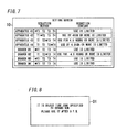
- the execution part 1101 has a function of displaying reduction contents including specific setting values and the like on the setting screen 10, when the reduction methods are selected through the setting screen 10 and the correspondence table is stored in the method storage part 1122.
- the execution part 1101 is configured to extract, when the correspondence table is stored in the method storage part 1122, as a trigger, extract, from the history storage part 1123, history data in the same time zone in the previous week as the object time zone (in which the reduction in electric power to be consumed is requested), and determine the setting values in the reduction contents according to the reduction request, with the history data as the reference value. Then, the execution part 1101 is configured to report the determined reduction contents to the operation display device 12 via the communication I/F 1112, and display the reduction content corresponding to each of the branch circuits or the load apparatuses 4 on the setting screen 10.
- the user can previously know what contents for the power reduction are actually executed to the branch circuits or the load apparatuses 4. As a result, when feeling dissatisfied with the displayed reduction contents, the user can change the reduction methods through the setting screen 10 until the user feels satisfied with the displayed reduction contents.
- a load apparatus 4 as a washing machine is made to correspond, in the correspondence table, to the reduction method (method of "T1") of shifting a timing, at which electric power is consumed by the load apparatus 4, from an object time zone (in which the reduction in electric power to be consumed is requested in the reduction request) to another time zone.
- the energy management device 1 is configured to display, on a display screen D1 of the washing machine, a message for allowing the user to use the washing machine after the object time zone (after 9 p.m.), as shown in Fig. 8 .
- the energy management device 1 may limit electric power itself to be consumed in the object time zone, by causing a branch breaker 22 of this branch circuit to carry out a breaking operation (by turning off the branch breaker 22) over the object time zone.
- this reduction method it is possible to save electric power in the object time zone by prohibiting, in the object time zone, use of a load apparatus 4, such as a washing machine, a dishwasher or a clothes dryer, which is allowed to shift a timing of using it as long as its operation is completed by a certain time.
- a load apparatus 4 such as a washing machine, a dishwasher or a clothes dryer
- the energy management device 1 can reduce all the amount of electric power to be consumed by the load apparatus 4 in the object time zone, it is possible to significantly reduce the amount of electric power to be consumed in the object time zone.
- a load apparatus 4 as an IH cooker is made to correspond, in the correspondence table, to the reduction method (method of "T2") of setting an upper limit to a magnitude of electric power to be consumed by the load apparatus 4.
- the energy management device 1 is configured to transmit, to the IH cooker, a control signal of setting 1kW as an upper limit of the electric power to be consumed.
- the energy management device 1 is configured to allow the IH cooker to output by voice a message of urging the user to perform an operation for suppressing the electric power to be consumed to the upper limit or less.
- examples of the output message include a message of "Electric power to be consumed is being limited by demand. Please turn down the heat.” and the like.
- the energy management device 1 can reduce the amount of electric power to be consumed in the object time zone only by providing a certain limitation to operation of such a load apparatus 4 without completely prohibiting the operation.
- a load apparatus 4 as a television is made to correspond, in the correspondence table, to the reduction method (method of "T3") of setting an upper limit to a length of a time period during which electric power is consumed by the load apparatus 4.
- the energy management device 1 is configured to detect a start of the use of the television in the object time zone, based on a status change notification that is received from the television, or an increase in electric power in a branch circuit to which the television is connected, and activate a timer for clocking a time period that is set as the upper limit, from the start of the use.
- the energy management device 1 when a time period during which the television is used in the object time zone reaches 2 hours, the energy management device 1 is configured to transmit, to the television, a control signal of turning off the television, or turn off a branch breaker 22, to which the television is connected, to turn off the television.
- the energy management device 1 may be configured to transmit a control signal to the television at the start of the use of the television to make the television activate an off timer so that the television is automatically turned off after 2 hours.
- the energy management device 1 can reduce the amount of electric power to be consumed in the object time zone only by providing a certain limitation to an operating time period of such a load apparatus 4 without completely prohibiting the operation.
- the energy management device 1 is configured to transmit, to the television, a control signal of turning off the television, or turn off a branch breaker 22, to which the television is connected, to turn off the television.
- the energy management device 1 can reduce the amount of electric power to be consumed in the object time zone only by providing a certain limitation to an operating time period of such a load apparatus 4 without completely prohibiting the operation thereof.
- the energy management device 1 includes the selection part 1102 that is configured to make a user select, from a plurality of predetermined reduction methods, the reduction methods to be stored in the method storage part 1122 and made to correspond to the branch circuits or the load apparatuses 4 individually. Therefore, the user can select the reduction methods for the branch circuits or the load apparatuses 4 individually, depending on an actual way of using each load apparatus 4. As a result, the actual way of using each load apparatus 4 is reflected in operation (control) for limiting the amount of electric power to be consumed in the consumer's house, performed by the energy management device 1, and accordingly, it is possible to easily give a user satisfaction regarding the operation for limiting the amount of electric power to be consumed in the consumer's house.
- the ways of using the load apparatuses 4 are not uniform, and the ways are different depending on the load apparatuses 4. Also, the ways are different depending on users. For example, regarding a load apparatus 4 as a washing machine, there may be two different ways, depending on users: a way in which washed clothes are dried indoors or dried with a clothes dryer; and a way in which the washed clothes are dried out of doors. That is, in the case of the former way, it is possible to easily give a user satisfaction regarding the first reduction method of shifting a timing, at which the washing machine is used, to save electric power in the object time zone.
- the user can select a reduction method to be made to correspond to the load apparatus 4, depending on the actual way of using the load apparatus 4, and accordingly, it is possible to easily give the user satisfaction regarding the operation for limiting the amount of electric power to be consumed in the consumer's house.
- An energy management system according to the present embodiment is different from that according to the First Embodiment in reduction methods that are stored in an energy management device 1 in advance.
- constituent elements similar to those of the First Embodiment are assigned with same reference numerals, and the explanations thereof are appropriately omitted.
- this reduction method is a method of limiting, in the object time zone, the operation mode of a load apparatus 4 in which one operation mode can be selected from a plurality of operation modes, such as an energy-saving mode (economy mode) and a normal mode, thereby reducing an amount of electric power to be consumed.
- the energy management device 1 is configured to forcibly switch, to the energy-saving mode, the operation mode of the television in the object time zone. Specifically, the energy management device 1 is configured to transmit, to the television, a control signal for switching the operation mode to the energy-saving mode at a start time of the object time zone, and then transmit, to the television, a control signal for switching the operation mode to the normal mode at an end time of the object time zone. In this way, the operation mode of the load apparatus 4 as the television is automatically switched, in the object time zone, to the energy-saving mode in which the power consumption is small, and accordingly, it is possible to reduce the amount of electric power to be consumed in the object time zone.
- the energy management device 1 can reduce the amount of electric power to be consumed in the object time zone only by providing a certain limitation to the operation mode without prohibiting the operation of such a load apparatus 4.
Landscapes
- Engineering & Computer Science (AREA)
- Power Engineering (AREA)
- Physics & Mathematics (AREA)
- Business, Economics & Management (AREA)
- General Physics & Mathematics (AREA)
- Health & Medical Sciences (AREA)
- Economics (AREA)
- Automation & Control Theory (AREA)
- General Engineering & Computer Science (AREA)
- Public Health (AREA)
- Primary Health Care (AREA)
- Strategic Management (AREA)
- Tourism & Hospitality (AREA)
- Marketing (AREA)
- General Business, Economics & Management (AREA)
- Human Resources & Organizations (AREA)
- Theoretical Computer Science (AREA)
- General Health & Medical Sciences (AREA)
- Water Supply & Treatment (AREA)
- Supply And Distribution Of Alternating Current (AREA)
- Remote Monitoring And Control Of Power-Distribution Networks (AREA)
- Management, Administration, Business Operations System, And Electronic Commerce (AREA)
Applications Claiming Priority (2)
| Application Number | Priority Date | Filing Date | Title |
|---|---|---|---|
| JP2012088837A JP6277537B2 (ja) | 2012-04-09 | 2012-04-09 | エネルギー管理装置、エネルギー管理システム、エネルギー管理方法、およびプログラム |
| PCT/JP2013/001425 WO2013153737A1 (ja) | 2012-04-09 | 2013-03-07 | エネルギー管理装置、エネルギー管理システム |
Publications (2)
| Publication Number | Publication Date |
|---|---|
| EP2838177A1 true EP2838177A1 (de) | 2015-02-18 |
| EP2838177A4 EP2838177A4 (de) | 2016-10-05 |
Family
ID=49327332
Family Applications (1)
| Application Number | Title | Priority Date | Filing Date |
|---|---|---|---|
| EP13775242.4A Ceased EP2838177A4 (de) | 2012-04-09 | 2013-03-07 | Energieverwaltungsvorrichtung und energieverwaltungssystem |
Country Status (4)
| Country | Link |
|---|---|
| EP (1) | EP2838177A4 (de) |
| JP (1) | JP6277537B2 (de) |
| AU (1) | AU2013248062B2 (de) |
| WO (1) | WO2013153737A1 (de) |
Cited By (2)
| Publication number | Priority date | Publication date | Assignee | Title |
|---|---|---|---|---|
| EP3082096A4 (de) * | 2013-12-10 | 2016-10-26 | Panasonic Ip Man Co Ltd | Nachfragevorhersagevorrichtung und -programm |
| EP3082074A4 (de) * | 2013-12-13 | 2016-11-30 | Panasonic Ip Man Co Ltd | Vorrichtung zur nachfragevorhersage, hilfssystem zur energiekonservierung |
Families Citing this family (7)
| Publication number | Priority date | Publication date | Assignee | Title |
|---|---|---|---|---|
| JP2015130768A (ja) * | 2014-01-08 | 2015-07-16 | パナソニックIpマネジメント株式会社 | エネルギー管理装置、およびエネルギー管理システム |
| JP5820892B2 (ja) * | 2014-01-09 | 2015-11-24 | 日本電信電話株式会社 | 電力需給制御装置及び電力需給制御方法 |
| KR101727390B1 (ko) | 2015-07-28 | 2017-04-26 | 엘에스산전 주식회사 | 전력 측정 시스템 및 이를 이용한 부하 전력 모니터링 시스템 및 그 동작 방법 |
| KR101717853B1 (ko) * | 2015-09-02 | 2017-03-27 | 엘에스산전 주식회사 | 전력 모니터링 시스템 및 그의 전력 모니터링 방법 |
| JP6782724B2 (ja) * | 2018-03-22 | 2020-11-11 | Kddi株式会社 | デマンドレスポンスの発動要請に対する電力抑制装置、プログラム及び方法 |
| JP7126206B2 (ja) * | 2019-02-28 | 2022-08-26 | パナソニックIpマネジメント株式会社 | デマンド監視システム、監視方法及びプログラム |
| KR102599363B1 (ko) * | 2021-02-04 | 2023-11-09 | 박근식 | 사용자기반의 ai에너지 절감 및 수요예측시스템 |
Family Cites Families (12)
| Publication number | Priority date | Publication date | Assignee | Title |
|---|---|---|---|---|
| JPH11313441A (ja) | 1998-04-27 | 1999-11-09 | Toshiba Corp | 家庭内電力dsmシステム |
| JP2004011836A (ja) * | 2002-06-10 | 2004-01-15 | Toyota Motor Corp | 湿式摩擦部材 |
| JP2004118366A (ja) * | 2002-09-25 | 2004-04-15 | Daikin Ind Ltd | 省エネルギー制御システム、省エネルギー制御方法、及び提示受付装置 |
| WO2008039759A2 (en) * | 2006-09-25 | 2008-04-03 | Intelligent Management Systems Corporation | System and method for resource management |
| JP2008092680A (ja) * | 2006-10-02 | 2008-04-17 | Matsushita Electric Works Ltd | エネルギマネジメント装置 |
| JP5276294B2 (ja) * | 2007-09-19 | 2013-08-28 | 大阪瓦斯株式会社 | 負荷低減計画策定システム及びデマンド制御システム |
| US8239073B2 (en) * | 2008-04-17 | 2012-08-07 | Asoka Usa Corporation | Systems and methods for controlling energy consumption |
| JP2009278795A (ja) * | 2008-05-15 | 2009-11-26 | Tempearl Ind Co Ltd | 生活エネルギー適正使用支援システム |
| JP2010124539A (ja) * | 2008-11-17 | 2010-06-03 | Oki Electric Ind Co Ltd | 電力使用制御方法及び電力使用制御サーバ |
| JP5466919B2 (ja) * | 2009-11-06 | 2014-04-09 | パナソニック株式会社 | 配電システム |
| JP5646206B2 (ja) * | 2010-04-28 | 2014-12-24 | 株式会社東芝 | 消費電力管理装置および消費電力管理方法 |
| JP2012039695A (ja) * | 2010-08-04 | 2012-02-23 | Sharp Corp | 接続機器管理システム |
-
2012
- 2012-04-09 JP JP2012088837A patent/JP6277537B2/ja active Active
-
2013
- 2013-03-07 EP EP13775242.4A patent/EP2838177A4/de not_active Ceased
- 2013-03-07 AU AU2013248062A patent/AU2013248062B2/en active Active
- 2013-03-07 WO PCT/JP2013/001425 patent/WO2013153737A1/ja not_active Ceased
Cited By (2)
| Publication number | Priority date | Publication date | Assignee | Title |
|---|---|---|---|---|
| EP3082096A4 (de) * | 2013-12-10 | 2016-10-26 | Panasonic Ip Man Co Ltd | Nachfragevorhersagevorrichtung und -programm |
| EP3082074A4 (de) * | 2013-12-13 | 2016-11-30 | Panasonic Ip Man Co Ltd | Vorrichtung zur nachfragevorhersage, hilfssystem zur energiekonservierung |
Also Published As
| Publication number | Publication date |
|---|---|
| AU2013248062A1 (en) | 2014-11-20 |
| JP2013219935A (ja) | 2013-10-24 |
| EP2838177A4 (de) | 2016-10-05 |
| WO2013153737A1 (ja) | 2013-10-17 |
| JP6277537B2 (ja) | 2018-02-14 |
| AU2013248062B2 (en) | 2015-09-17 |
Similar Documents
| Publication | Publication Date | Title |
|---|---|---|
| AU2013248062B2 (en) | Energy management device and energy management system | |
| JP2012094077A (ja) | 家庭用エネルギー管理システム | |
| EP2587726B1 (de) | Verfahren für steuerungskomponente für netzwerksystem | |
| EP2587734B1 (de) | Netzwerksystem | |
| EP3498905B1 (de) | Netzwerksystem | |
| US20140188299A1 (en) | Display device, display method, and program product | |
| WO2012036799A1 (en) | Network system | |
| JP2014131447A (ja) | 表示装置、表示方法及びプログラム | |
| JP6264700B2 (ja) | エネルギー管理装置、エネルギー管理システム、エネルギー管理方法、およびプログラム | |
| CN103855807A (zh) | 一种可实现家庭智能电网管理的系统、方法及执行模块 | |
| JP6074843B2 (ja) | コントローラ | |
| US9407114B2 (en) | Network system and control method thereof | |
| JP4584819B2 (ja) | 負荷監視制御方法およびシステム | |
| AU2015264838B2 (en) | Energy Management Device and Energy Management System | |
| JPWO2017090173A1 (ja) | 制御装置、充電情報表示方法及びプログラム | |
| KR20160040401A (ko) | 홈 네트워크 기반의 에너지 사용량 모니터링 시스템 및 에너지 사용량 모니터링 방법 | |
| KR101955875B1 (ko) | 냉장고 | |
| KR101656885B1 (ko) | 네트워크 시스템 및 이를 구성하는 컴포넌트 | |
| JP6746012B2 (ja) | 制御装置、制御システム、制御方法およびプログラム | |
| WO2017022173A1 (ja) | 電力管理システム、電力管理装置、電力管理方法、及び、プログラム | |
| KR101918297B1 (ko) | 가전제품 | |
| KR20120029565A (ko) | 네트워크 시스템 | |
| KR20120040317A (ko) | 지능형 콘센트 및 그를 이용한 대기전력 제어방법 | |
| WO2014076900A1 (ja) | コントローラおよび省エネ制御システム | |
| WO2012036851A2 (en) | Component for network system |
Legal Events
| Date | Code | Title | Description |
|---|---|---|---|
| PUAI | Public reference made under article 153(3) epc to a published international application that has entered the european phase |
Free format text: ORIGINAL CODE: 0009012 |
|
| 17P | Request for examination filed |
Effective date: 20141031 |
|
| AK | Designated contracting states |
Kind code of ref document: A1 Designated state(s): AL AT BE BG CH CY CZ DE DK EE ES FI FR GB GR HR HU IE IS IT LI LT LU LV MC MK MT NL NO PL PT RO RS SE SI SK SM TR |
|
| AX | Request for extension of the european patent |
Extension state: BA ME |
|
| DAX | Request for extension of the european patent (deleted) | ||
| RA4 | Supplementary search report drawn up and despatched (corrected) |
Effective date: 20160906 |
|
| RIC1 | Information provided on ipc code assigned before grant |
Ipc: G05B 15/02 20060101AFI20160831BHEP Ipc: H02J 3/14 20060101ALI20160831BHEP Ipc: G06Q 50/06 20120101ALN20160831BHEP |
|
| 17Q | First examination report despatched |
Effective date: 20190103 |
|
| REG | Reference to a national code |
Ref country code: DE Ref legal event code: R003 |
|
| STAA | Information on the status of an ep patent application or granted ep patent |
Free format text: STATUS: THE APPLICATION HAS BEEN REFUSED |
|
| 18R | Application refused |
Effective date: 20200317 |