EP2838209A1 - Procédé destiné au fonctionnement d'une application radio logicielle - Google Patents
Procédé destiné au fonctionnement d'une application radio logicielle Download PDFInfo
- Publication number
- EP2838209A1 EP2838209A1 EP13776240.7A EP13776240A EP2838209A1 EP 2838209 A1 EP2838209 A1 EP 2838209A1 EP 13776240 A EP13776240 A EP 13776240A EP 2838209 A1 EP2838209 A1 EP 2838209A1
- Authority
- EP
- European Patent Office
- Prior art keywords
- radio
- application
- platform
- processor
- radio application
- Prior art date
- Legal status (The legal status is an assumption and is not a legal conclusion. Google has not performed a legal analysis and makes no representation as to the accuracy of the status listed.)
- Withdrawn
Links
Images






Classifications
-
- G—PHYSICS
- G06—COMPUTING OR CALCULATING; COUNTING
- G06F—ELECTRIC DIGITAL DATA PROCESSING
- G06F9/00—Arrangements for program control, e.g. control units
- G06F9/06—Arrangements for program control, e.g. control units using stored programs, i.e. using an internal store of processing equipment to receive or retain programs
- G06F9/44—Arrangements for executing specific programs
-
- G—PHYSICS
- G06—COMPUTING OR CALCULATING; COUNTING
- G06F—ELECTRIC DIGITAL DATA PROCESSING
- G06F8/00—Arrangements for software engineering
- G06F8/60—Software deployment
- G06F8/61—Installation
-
- G—PHYSICS
- G06—COMPUTING OR CALCULATING; COUNTING
- G06F—ELECTRIC DIGITAL DATA PROCESSING
- G06F8/00—Arrangements for software engineering
- G06F8/60—Software deployment
- G06F8/65—Updates
- G06F8/654—Updates using techniques specially adapted for alterable solid state memories, e.g. for EEPROM or flash memories
-
- G—PHYSICS
- G06—COMPUTING OR CALCULATING; COUNTING
- G06F—ELECTRIC DIGITAL DATA PROCESSING
- G06F9/00—Arrangements for program control, e.g. control units
- G06F9/06—Arrangements for program control, e.g. control units using stored programs, i.e. using an internal store of processing equipment to receive or retain programs
- G06F9/44—Arrangements for executing specific programs
- G06F9/445—Program loading or initiating
-
- G—PHYSICS
- G06—COMPUTING OR CALCULATING; COUNTING
- G06F—ELECTRIC DIGITAL DATA PROCESSING
- G06F9/00—Arrangements for program control, e.g. control units
- G06F9/06—Arrangements for program control, e.g. control units using stored programs, i.e. using an internal store of processing equipment to receive or retain programs
- G06F9/44—Arrangements for executing specific programs
- G06F9/455—Emulation; Interpretation; Software simulation, e.g. virtualisation or emulation of application or operating system execution engines
- G06F9/45533—Hypervisors; Virtual machine monitors
- G06F9/45558—Hypervisor-specific management and integration aspects
-
- H—ELECTRICITY
- H04—ELECTRIC COMMUNICATION TECHNIQUE
- H04B—TRANSMISSION
- H04B1/00—Details of transmission systems, not covered by a single one of groups H04B3/00 - H04B13/00; Details of transmission systems not characterised by the medium used for transmission
- H04B1/0003—Software-defined radio [SDR] systems, i.e. systems wherein components typically implemented in hardware, e.g. filters or modulators/demodulators, are implented using software, e.g. by involving an AD or DA conversion stage such that at least part of the signal processing is performed in the digital domain
-
- H—ELECTRICITY
- H04—ELECTRIC COMMUNICATION TECHNIQUE
- H04L—TRANSMISSION OF DIGITAL INFORMATION, e.g. TELEGRAPHIC COMMUNICATION
- H04L41/00—Arrangements for maintenance, administration or management of data switching networks, e.g. of packet switching networks
- H04L41/08—Configuration management of networks or network elements
- H04L41/0803—Configuration setting
- H04L41/0813—Configuration setting characterised by the conditions triggering a change of settings
- H04L41/0816—Configuration setting characterised by the conditions triggering a change of settings the condition being an adaptation, e.g. in response to network events
-
- H—ELECTRICITY
- H04—ELECTRIC COMMUNICATION TECHNIQUE
- H04L—TRANSMISSION OF DIGITAL INFORMATION, e.g. TELEGRAPHIC COMMUNICATION
- H04L41/00—Arrangements for maintenance, administration or management of data switching networks, e.g. of packet switching networks
- H04L41/08—Configuration management of networks or network elements
- H04L41/0803—Configuration setting
- H04L41/0813—Configuration setting characterised by the conditions triggering a change of settings
- H04L41/082—Configuration setting characterised by the conditions triggering a change of settings the condition being updates or upgrades of network functionality
-
- H—ELECTRICITY
- H04—ELECTRIC COMMUNICATION TECHNIQUE
- H04W—WIRELESS COMMUNICATION NETWORKS
- H04W4/00—Services specially adapted for wireless communication networks; Facilities therefor
-
- G—PHYSICS
- G06—COMPUTING OR CALCULATING; COUNTING
- G06F—ELECTRIC DIGITAL DATA PROCESSING
- G06F9/00—Arrangements for program control, e.g. control units
- G06F9/06—Arrangements for program control, e.g. control units using stored programs, i.e. using an internal store of processing equipment to receive or retain programs
- G06F9/44—Arrangements for executing specific programs
- G06F9/455—Emulation; Interpretation; Software simulation, e.g. virtualisation or emulation of application or operating system execution engines
- G06F9/45533—Hypervisors; Virtual machine monitors
- G06F9/45558—Hypervisor-specific management and integration aspects
- G06F2009/45595—Network integration; Enabling network access in virtual machine instances
Definitions
- the present invention relates to operational structures of radio applications for a software-defined radio (SDR) terminal, and more specifically to operational structures of unified radio applications which have hardware-independency and can be developed as corresponding to various radio platforms.
- SDR software-defined radio
- the technologies of the present invention may cover software define radio, digital radio communications, baseband processors, application processors, application stores, long term evolution (LTE), worldwide interoperability for microwave (WiMax), and radio applications.
- LTE long term evolution
- WiMax worldwide interoperability for microwave
- various radio applications such as LTE, WiMax, wireless microphone, walkie-talkie, etc. can be downloaded from application stores and installed into a cellular phone so that the cellular phone can be changed into an LTE terminal or a WiMax terminal, or can be used as a wireless microphone, a walkie-talkie, etc. Therefore, the present invention may be applied to smart phones which need to support various radio access technologies such as LTE, wideband code division multiple access (WCDMA), and WIFI.
- LTE Long Term Evolution
- WCDMA wideband code division multiple access
- SCA software communication architecture
- SDR software defined radio
- OS real-time operating system
- the purpose of the present invention for resolving the above-described problems is to provide operational structures of unified radio applications which can be freely developed, distributed, installed, and executed as corresponding to various radio platforms.
- a method of operating a radio application in a radio processor layer of a terminal having a radio processor may comprise determining whether a shadow radio platform to which the radio application is targeted is identical to a real radio platform of the terminal; and executing configuration codes of the radio application in the radio processor when the shadow radio platform is identical to the real radio platform of the terminal.
- the configuration codes may include user-defined function block codes for configuring user-defined function blocks of the radio application, and a radio library for configuring standard function blocks used by the radio application in form of execution codes executable on the real radio platform.
- the standard function blocks may be implemented as dedicated hardware logics executed by the radio application through a hardware abstraction layer (HAL) of the radio processor layer.
- HAL hardware abstraction layer
- the method may further comprise downloading a radio application package including the configuration codes of the radio application from a server.
- the radio application may operate on at least one of the radio processor and an application processor of the terminal and interwork with a radio control framework providing the radio application with operation environments.
- the radio control framework includes at least one of: a configuration manager (CM) performing installation/uninstallation of the radio application and creating/deleting an instance of the radio application and managing radio parameters for the radio application; a radio connection manager (RCM) performing activation/deactivation of the radio application and managing user data flow switching between radio applications; a flow controller (FC) controlling sending/receiving and flows of user data packets; a multi-radio controller (MRC) scheduling requests for spectrum resources issued by radio applications; and a resource manager (RM) sharing radio resources with radio applications.
- CM configuration manager
- RCM radio connection manager
- FC flow controller
- MRC multi-radio controller
- RM resource manager
- a method of operating a radio application in a radio processor layer of a terminal having a radio processor may comprise determining whether a shadow radio platform to which the radio application is targeted is identical to a real radio platform of the terminal; and executing configuration codes of the radio application in the radio processor by compiling the configuration codes through a radio virtual machine (RVM) when the shadow radio platform is different from the real radio platform of the terminal.
- RVM radio virtual machine
- the configuration codes may include user-defined function block codes for configuring user-defined function blocks of the radio application in intermediate representation (IR) form which can be converted into execution codes executable on the real radio platform.
- IR intermediate representation
- the RVM may include a just-in-time (JIT) compiler or which compiles the configuration codes into execution codes of the real radio platform.
- JIT just-in-time
- the RVM may include an ahead-of-time (AOT) compiler which compiles the configuration codes into execution codes of the real radio platform.
- AOT ahead-of-time
- the terminal may have native implementations of standard function blocks in the radio processor layer.
- the terminal may have standard function blocks implemented as dedicated hardware logics executed by the radio application through a hardware abstraction layer (HAL) of the radio processor layer.
- HAL hardware abstraction layer
- the method may further comprise downloading a radio application package including the configuration codes of the radio application from a server.
- the radio application may operate on at least one of the radio processor and an application processor of the terminal and interwork with a radio control framework providing the radio application with operation environments.
- the radio control framework may include at least one of: a configuration manager (CM) performing installation/uninstallation of the radio application and creating/deleting an instance of the radio application and managing radio parameters for the radio application; a radio connection manager (RCM) performing activation/deactivation of the radio application and managing user data flow switching between radio applications; a flow controller (FC) controlling sending/receiving and flows of user data packets; a multi-radio controller (MRC) scheduling requests for spectrum resources issued by radio applications; and a resource manager (RM) sharing radio resources with radio applications.
- CM configuration manager
- RCM radio connection manager
- FC flow controller
- MRC multi-radio controller
- RM resource manager
- Relational terms such as first, second, A, B, and the like may be used for describing various elements, but the elements should not be limited by the terms. The terms are used solely for distinguishing one element from another. For instance, without departing the scope of the present disclosure, a first element may be named as a second element, and similarly, a second element may be named as a first element.
- the term "and/or" encompasses both combinations of the plurality of related items disclosed and any item from among the plurality of related items disclosed.
- Terminologies used for explaining the present invention are defined as follows. Other terminologies except the following terminologies will be defined in the corresponding parts of the present specification.
- FIG. 1 is a block diagram illustrating a monolithic kernel and a micro kernel constituting a part of operational structure of unified radio applications according to example embodiments of the present invention.
- a monolithic kernel is a kernel to which all necessary functions are integrated. Since all necessary functions exist in the same memory space, each of the functions provided by the kernel may be accessed by using a function call method. Thus, its implementation can be simplified, and system resources can be efficiently utilized. However, it is difficult that the implemented kernel is not easily ported to various hardware environments or different systems. Also, when its functions are extended, a size of the kernel may become too large, and management of the kernel may become difficult.
- a micro kernel is a kernel in which necessary functions are designed as small server modules and only minimum functions for managing the server modules are implemented as a core part of the kernel.
- This type of kernel has advantages that expansion and reconfiguration of its functions are easy and it can be easily reused by other systems.
- frequent message exchanges and context switching may occur during a procedure of using services, there is a shortcoming that its working speed may become relatively lower.
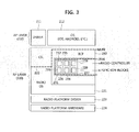
- FIGS. 2 and 3 are block diagrams to explain a software architecture environment on which a radio application according to the present invention is executed.
- a software architecture may comprise an application processor layer 110 which operates on an application processor (AP) and a radio processor layer 120 which operates on a radio processor (RP).
- AP application processor
- RP radio processor
- the radio processor may be also referred to as a baseband processor (BP).
- FIG.2 illustrates a software architecture environment where a radio control framework (RCF), which is described later, is divided into two parts - a part being executed on the AP (referred to as an application processor layer part) and a part being executed on the RP (referred to as a radio processor layer part), and executed on the two processors.
- FIG. 3 illustrates a software architecture environment where a RCF is executed only on the radio processor.
- RCF radio control framework
- a non-real time OS such as Andriod OS of Google, iOS of Apple, etc. may operate on the AP, and a real time OS (hereinafter, referred to as a 'radio OS') may operate on the RP.
- a 'radio OS' a real time OS
- the non-real time OS operating on the AP layer may be referred to as 'OS'
- the real time OS operating on the RP layer may be referred to as 'radio OS'.
- the AP layer the RP layer, and components constituting the radio control framework will be described in detail.
- the AP layer comprises the following components, as shown in FIG. 2 and FIG. 3 .
- radio control framework is configured to operate on the AP and the RP both (as shown in FIG. 2 ), an AP layer part 114 of the radio control framework may exist on the OS. If the radio control framework is configured to operate only on the RP (as shown in FIG. 3 ), the radio control framework does not exist on the AP layer.
- a communication service layer 113 may exist on the OS of the AP.
- the communication service layer may be a layer providing at least some of the following three services to the radio control framework.
- the first service is related to an administrative. It may be a service related to installation/uninstallation of radio applications, creating/deleting instances of radio applications, and acquisition of a list of radio applications in each status (installed, instanced, activated).
- the second service is related to connection control. It may be a service related to activation/deactivation of radio applications, creation of data flow, creation of network allocation, and acquisition of a list of radio applications in each status (installed, instanced, activated).
- this service is related to data flow. That is, this service is a service related to sending/receiving user data.
- the communication service layer may be configured to comprise an administrator application, a mobility policy manager application, a networking stack (i.e. a protocol stack operating on the communication service layer), and a monitor application.
- the communication service layer may comprise only some of the above-described components, or may further comprise additional components as well as the above-described components. Also, one or more components among the above components may be integrated into a single component existing within the communication service layer. Also, the above-described components are only examples of components which the communication service layer can comprise in order to support services which should be performed by the communication service layer. That is, the communication service layer may be defined based on functions performed by it. The above-described exemplary composition of components does not restrict composition of the communication service layer.
- radio applications 131, 134, and 137 to which distribution/installation/operation methods according to the present invention are applied may respectively comprise AP layer parts 132, 135, and 138 and RP layer parts 133, 136, and 139.
- a radio controller (RC) which is the AP layer part of radio application may be configured to transmit context information to a monitor application of the communication service layer, transmit data to a networking stack of the communication service layer, and receive data from the networking stack.
- the RP layer comprises the following components, as shown in FIG. 2 and FIG. 3 .
- a RP layer part 124 of the radio control framework may exist on the radio OS. If the radio control frame work operates only on the RP (as shown in FIG. 3 ), the radio control framework does not exist on the AP layer. That is, the radio control framework exists only on the RP layer.
- Radio controllers 132, 135, and 138 of respective radio applications may be configured to transmit context information to a monitor application of the communication service layer, transmit data to a networking stack of the communication service layer, and receive data from the networking stack.
- a multi-radio interface is an interface between the communication service layer and the control framework
- a unified radio application interface is an interface between the radio application and the control framework.
- a radio application is an application enabling communications of a mobile terminal, and may be distributed in form of a radio application package.
- Components of a radio application package may be configured as follows.
- the radio application package may be downloaded onto the OS of the application processor layer, and the user-defined function block codes and the radio library may be loaded from the application processor to the radio processor by referring to the pipeline configuration metadata, and finally loaded to the radio OS on the radio processor layer.
- the radio control framework (RCF) 130 or 230 is a component for providing operation environment of radio applications.
- components of the radio control framework may be classified into two groups 114 and 124. That is, one group operates on the AP, and other group operates on the RP. It may be determined differently according to each vendor which components of the RCF operate on the RP (i.e. in real-time) and which components of the RCF operate on the AP (i.e. in non-real-time).
- the radio control framework is configured to operate only on the RP (i.e. a configuration of FIG. 3 ), the radio control framework exists only on the RP layer without discrimination of a RP layer part and an AP layer part.
- the RCF may include at least some of the following 5 components for managing radio applications.
- the radio control framework may comprise only some of the following 5 components, and may further comprise additional components as well as the following 5 components. Also, one or more components among the following components may be integrated into a single component existing within the radio control framework.
- the role of the radio control framework may be defined based on functions performed by the components which will be described.
- the following exemplary components do not restrict composition of the radio control framework. That is, the radio control framework may have various configurations at least some of functions of the following components.
- radio application package If a radio application package is downloaded, user-defined function block code and radio library which should operate on the RP layer are installed so that they can be accessed in the RP layer.
- Configcodes may include only user-defined function block code, or may include radio library as well as the user-defined function block code. Configcodes may be in form of executable codes or Intermediate Representation (IR).
- IR Intermediate Representation
- a real radio platform is defined as a target radio platform
- a concept of a shadow radio platform is defined as a virtual entity having hardware abstraction on the target radio platform. That is, a shadow radio platform may mean a virtual radio platform into which developers of radio applications virtualize an operation environment of radio applications. For example, a shadow radio platform may be equal to or different from a target radio platform. If the Shadow radio platform is different from the target radio platform, the shadow radio platform may be understood as an abstract device independent of hardware. That is, the shadow radio platform may be a radio virtual machine (RVM).
- RVM radio virtual machine
- the RVM performs virtualization functions for helping the above-described configcodes to operate on the actual target radio platform.
- the implementation may include the Back-end Compiler which might provide Just-in-Time (JIT) or Ahead-of-Time (AOT) method for compilation of configcodes into executable codes of the target radio platform.
- JIT Just-in-Time
- AOT Ahead-of-Time
- FIG. 4 is a conceptual diagram to explain a radio processor layer software architecture of radio applications according to the present invention.
- the radio process provides a mobile device with communication capabilities, and the software architecture for radio processor, which is illustrated in FIG. 4 , may be configured to comprise the following components.
- the configcodes are interpreted by RVM when the shadow radio platform is equal to RVM, or are equal to executable codes when RVM is equal to the target radio platform.
- the shadow radio platform can be either RVM or a target radio platform. If the Shadow radio platform is equal to the target radio platform, then front-end compiler will generate executable code for the target radio platform and configcodes is equivalent to the executable code for that radio platform.
- the RVM is an abstract machine which is capable of executing configcodes. It is independent of the hardware.
- the configcodes are executed on a target platform through a specific RVM.
- RVM includes a back-end compiler which might provide Just-in-Time (JIT) or Ahead-of-Time (AOT) method for compilation of configcodes into executable codes.
- JIT Just-in-Time
- AOT Ahead-of-Time
- the radio library consists of function blocks representing the computational basis.
- the radio application can be expressed as a set of these interconnected function blocks.
- Function blocks of the radio library are represented in the normative language of the radio platform.
- the native implementation of the radio library provides executable codes of function blocks from the library for the target platform.
- the radio library is extendable.
- Operational structure of unified radio applications may be represented considering two different cases.
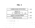
- One case is when RA configcodes are executable on a target radio platform (illustrated in FIG. 5 ) and the other case is when RA configcodes are Intermediate Representation (IR) that is to be back-end compiled at a given mobile device (illustrated in FIG. 6 ).
- RA configcodes are executable on a target radio platform (illustrated in FIG. 5 ) and the other case is when RA configcodes are Intermediate Representation (IR) that is to be back-end compiled at a given mobile device (illustrated in FIG. 6 ).
- IR Intermediate Representation
- FIG. 5 is a hierarchy structure diagram to explain an example of operational structure of unified radio applications according to the present invention
- FIG. 6 is a hierarchy structure diagram to explain another example of operational structure of unified radio applications according to the present invention.
- a radio and user-defined function blocks (UDFB) library needed for execution of a given radio application are included in executable configcodes of the radio application.
- UDFB user-defined function blocks
- a native implementation of the radio library should be additionally prepared in a given mobile device.
- the native implementation of the radio library is provided by a core chip vendor because the radio library includes standard function blocks (SFB) implemented on the core processor.
- the radio library i.e. native implementation
- the radio library which can be implemented without dedicated hardware accelerator(s)
- the standard function blocks are supported by dedicated hardware logic accelerator(s) through the radio hardware abstract (HAL) layer shown in FIG. 5 and FIG.6 . That is, every time when the standard function blocks implemented using dedicated hardware logics are called by given radio application codes, the standard function blocks should be executed on the corresponding dedicated hardware logic accelerator(s) through the radio HAL, regardless of whether the radio application configcodes are executable codes or intermediate representation.
- the radio HAL also includes hardware abstraction for interfaces prepared for user-defined function block library(s).
- the standard function blocks may be function blocks which are commonly used by various radio applications, for example, a Fast Fourier Transform (FFT) block. Also, the standard function blocks may be function blocks which should be efficiently implemented using a special purpose accelerator in a given radio platform, for example, a turbo coder block.
- FFT Fast Fourier Transform
- a standard function block set (UDFB set) shown in FIG. 6 includes all user-defined function blocks which are used by given radio application(s). It is important that any standard function block can be modified and/or extended by replacing it with a proper standard function block which is a modified and/or extended version of the standard function block to be replaced. Therefore, some user-defined function blocks can be good candidates for standard function block extension, which means they might be added as standard function blocks later. In that case, after addition, they will become atomic as the normal standard function blocks. Since the user-defined function block Set (UDFB set) is to be provided by radio application provider, i.e.
- radio platform vendor instead of radio platform vendor, in order for radio control framework to be able to perform basic controls of every UDFB's event and/or command, a standard set of control interfaces such as "start”, “stop”, “pause”, “get_port” and “initialize” may have to be specified for the corresponding user-defined function blocks.
- an ETSI RRS may specify a standard set of control interfaces for each user-defined function block to be implemented properly via the standard set of control interfaces. Specification of the standard control interfaces for user-defined function blocks may be given in the document of Protocol/Interface technical specification (TS).
- the radio platforms shown in FIGS. 5 and 6 generally comprise both core(s) and dedicated hardware accelerator(s) for implementing each of function blocks.
- the operational structure of unified radio applications may comprise the following components.
- FIG. 7 is a conceptual diagram to explain implementations of function block libraries of a given radio platform according to the present invention. Referring to FIG. 7 , illustrated are implementations of function blocks on a given radio platform which consists of core(s) and various kinds of peripheral devices.
- the number of standard function blocks implemented on a core processor has been set to M and the number of standard function blocks implemented on dedicated hardware logic accelerators has been set to N.
- standard function blocks to be implemented using dedicated hardware logic accelerator such as FFT, Turbo decoder, Multi-Input-Multi-Output (MIMO) decoder, etc. can be implemented directly on the corresponding dedicated hardware logic accelerator for high performance and low power consumption.
- Those standard function blocks are supported by the radio HAL for implementation on the dedicated accelerator(s). This means that, when each of standard function blocks to be implemented on the dedicated accelerator is called in a radio application, it is executed directly on the corresponding dedicated accelerator through the radio HAL.
- core processor such as bit-reverse, multiply and accumulation, etc.
- RA a given core (e.g. ARM with Neon).
- the execution codes required on a radio processor consists of the following two parts.
- One part is execution codes for standard function blocks executed on programmable core(s) and the other part is radio HAL codes for standard function blocks implemented on dedicated accelerators.
- UDFB should be written with standard interfaces. As shown in FIG. 7 , it should be observed that the standard interfaces of UDFB might be associated with either SFB(s) implemented on core processor or SFB(s) implemented on dedicated hardware accelerator, or both.
- FIG. 8 is a diagram illustrating an overall architecture of a mobile device with all reference points specified in between corresponding components.
- each solid line between two blocks denotes a reference point defined between the two blocks through which direct interactions between the two blocks are performed.
- each dotted line between two blocks denotes that interactions between the two blocks is performed through radio OS based on commands issued by a corresponding block.
- blocks in RCF i.e. CM, RCM, MRC, and RM
- each reference point is based on the three kinds of interfaces - MURI which are interfaces between components of communication services layer and those of RCF, URAI which are interfaces between URA and component of RCF, and Reconfigurable Radio Frequency Interfaces (RRFI) which are interfaces between URA and Radio Frequency (RF) part.
- MURI which are interfaces between components of communication services layer and those of RCF
- URAI which are interfaces between URA and component of RCF
- RRFI Reconfigurable Radio Frequency Interfaces
- interfaces between components of RCF have also been defined as reference points.
- Reference Point 1 Interfaces for installation/uninstallation and creating/deleting instance of radio application
- FIG. 9 is a diagram illustrating reference points for installation/uninstallation and creating/deleting an instance of a radio application.
- CF1a is an interface between an administrator and a configuration manager (CM), which is for the administrator to request CM to perform installing, uninstalling of RA or for the administrator to receive response of the request from CM.
- CM configuration manager
- CF2a is an interface between a mobility policy manager (MPM) and CM, which is for MPM to request CM to perform creating instance or deleting instance of RA or for MPM to receive response of the request from CM.
- MPM mobility policy manager
- CF4 is an interface between CM and a multiradio controller (MRC), which is for CM to request MRC to send parameters related to radio resources to CM, or for CM to receive response of the request (i.e. the parameters related to radio resources) from MRC during the procedure of creating instance of RA.
- MRC multiradio controller
- CF5 is an interface between CM and a resource manager (RM), which is for CM to request RM to send parameters related to computational resources to CM, or for CM to receive response of the request (i.e. the parameters related to computational resources) from RM during the procedure of creating instance of RA.
- RM resource manager
- FIG. 10 is a diagram illustrating reference points for obtaining lists of radio applications.
- CF1b is an interface between the administrator and CM, which is for the administrator to request CM to send the RA list to Administrator, or for Administrator to receive response of the request (i.e. the RA list) from CM.
- Reference Point CF2b is an interface between MPM and CM, which is for MPM to request CM to send the RA list to MPM, or for MPM to receive response of the request (i.e. the RA list) from CM.
- Reference Point 3 Interfaces for activation/deactivation of radio application.
- FIG. 11 is a diagram illustrating reference points for activation/deactivation of radio application.
- CTRL1a is an interface between the MPM and a radio connection manager (RCM), which is for MPM to request RCM to perform activation/deactivation of radio applications, or for MPM to receive response of the request (i.e. activation/deactivation of RA) from RCM.
- RCM radio connection manager
- Reference Point 4 Interfaces for transferring context information
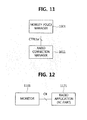
- FIG. 12 is a diagram illustrating reference points for transferring context information.
- CII is an interface between Monitor and RC in RA, which is for Monitor to request RC in RA to send context information to Monitor, or for Monitor to receive response of the request (i.e. the context information) from RC in RA.
- the context information is generated from corresponding function block(s) of RA(s) and transferred to RC. There should be interfaces between RC within a radio application and each of corresponding function blocks. This means that BBI for transferring context information between the RC and each of the corresponding function blocks should be defined.
- Reference Point 5 Interfaces for creating data flow and sending/receiving user data
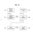
- FIG. 13 is a diagram illustrating reference points for creating data flow and sending/receiving user data.
- CTRL1b is an interface between MPM and RCM, which is for MPM to request RCM to form data flow or network association with peer equipment, or for MPM to receive response of the request from RCM.
- Reference Point CTRL2 is an interface between RCM and FC, which is for RCM to request FC to form data flow, or for RCM to receive response of the request from FC.
- Reference Point DCTRL1 is an interface between FC and Networking stack, which is for FC to receive/transfer user data from/to Networking stack for the procedure of sending/receiving data. It also includes an acknowledgement of transmit user data from FC to Networking stack upon completion of sending data. It also includes an acknowledgement of transmit user data from FC to Networking stack upon completion of sending data.
- Reference Point DCTRL2 is an interface between FC and RA, which is for FC to transfer the transmit user data to RA and to request RA to transfer the information of transmit user data such as throughput, data bandwidth, etc. to FC.
- DCTRL2 interface is also used for FC to receive response of the request from RA. In the case of the procedure of receiving data, DCTRL2 interface is used to transfer the receive user data from RA to FC.
- Reference Point DCTRL3 is an interface between RA and RF transceiver (XCVR) with antenna(s), which is for RA to receive/transfer receive/transmit user data from/to RF XCVR with antenna.
- XCVR RF transceiver
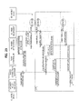
- FIG. 14 is a diagram illustrating signaling associated with the installation and uninstallation of radio application.
- the administrator sends a DownloadRAPReq signal including a RAP identification (ID) to a radio apps store.
- ID RAP identification
- the administrator receives the DownloadRAPCnf signal including RAP ID and RAP from the radio apps store.
- the administrator sends an InstallRAReq signal including RAP ID to CM to request radio application installation.
- CM first performs the procedure of certifying the RA code in order to verify its compatibility, authentication, etc.
- the CM sends an InstallRAReq signal including RAP ID to File Manager (FM) to perform installation of RA.
- FM File Manager
- FM performs installation of RA and transfers InstallRACnf signal including RA ID to CM, which transfers InstallRACnf signal including RA ID to Administrator.
- CM first sends CompileReq signal including RAP ID to Back-end Compiler in advance of RA installation. After completion of back-end compilation, Back-end Compiler transfers CompileCnf signal including RAP ID to CM, which performs the procedure of certifying usability of the back-end compiled RA code.
- CM reports Administrator the failure of RA installation using InstallRAFailCnf signal including RAP ID and failure reason.
- the administrator transfers an UninstallRAReq signal including ID of RA to be uninstalled to CM.
- the CM sends an UninstallRAReq signal including RA ID to FM.
- FM performs uninstallation of RA and transfers UninstallRACnf signal including RA ID as an acknowledgement of uninstallation completion to CM.
- the CM sends an UninstallRACnf signal including RA ID to Administrator
- FIG. 15 is a diagram illustrating signaling associated with the procedure of creating/deleting instance of radio application.
- MPM For creating instance of installed RA, MPM transfers InstantiateRAReq signal including ID of RA to be instantiated to CM.
- the CM transfers a RMParameterReq signal and a MRCParameterReq signal including ID of RA to get parameters needed for RA activation (e.g. Forward Error Correction (FEC) parameters, MIMO parameters, bandwidth, etc.) to RM and MRC.
- FEC Forward Error Correction
- the CM receives an RMParameterCnf signal including ID of RA and radio resource parameters from RM.
- the CM receives a MRCParameterCnf signal including ID of RA and computational resource parameters from MRC.
- the CM Upon completion of receiving parameters needed for RA activation, the CM transfers RA ID and the parameters for performing the RA instantiation to the radio OS.
- the CM Upon completion of creating instance, the CM transfers an InstantiateRACnf signal including RA ID to MPM.
- RM and/or MRC reports the failure of parameters transfer to the CM using RMParameterFailCnf and/or MRCParameterFailCnf, respectively.
- CM If the creating instance of RA fails, i.e. CM receives RMParameterFailCnf and/or MRCParameterFailCnf signal, CM reports the instantiation failure to MPM using InstantiateRAFailCnf signal.
- MPM transfers ID of RA to be deleted using a DeInstantiateRAReq signal to CM.
- the radio OS Upon the request of the CM for the radio OS to perform deleting instance of RA, the radio OS deletes the instance of designated RA.
- the CM Upon completion of deleting instance, the CM acknowledges deleting instance of RA to MPM using a DeInstantiateRACnf signal.
- FIG. 16 is a signal diagram illustrating a procedure of lint checking of radio applications.
- the administrator or MPM transfers a ListRAReq signal to CM for obtaining the radio application list.
- the CM transfers RA list information to the administrator or MPM using an RAList signal.
- FIG. 17 is a signaling diagram illustrating a procedure of activating radio application.
- the MPM transfers an ActivateReq signal including ID of RA to request RA activation to RCM.
- ROS activates the designated RA.
- RCM acknowledges the completion of RA activation by sending ActivateCnf signal to MPM.
- RCM reports the failure of RA activation to MPM by transferring the failed RA ID and failure reason in ActivateFailCnf signal.
- FIG. 18 is a signaling diagram illustrating a procedure of deactivating radio application.
- MPM transfers a HardDeactivateReq signal including ID of RA to request hard deactivation of the designated RA to RCM.
- the radio OS Upon the request of RCM for the radio OS to perform hard deactivation of RA, the radio OS deactivates the designated RA.
- RCM acknowledges the completion of hard deactivation of RA by sending a HardDeactivateCnf signal to MPM.
- MPM transfers a SoftDeactivateReq signal including ID of RA to request soft deactivation of the designated RA to RCM.
- the radio OS Upon the request of RCM for the radio OS to perform soft deactivation of RA, the radio OS deactivates the designated RA.
- RCM acknowledges the completion of soft deactivation of RA by sending SoftDeactivateCnf signal to MPM.
- FIG. 19 is a signaling diagram illustrating a procedure of transferring context information.
- a procedure for a radio application to transfer context information to a monitor or a baseband parameter aggregation (BPA) unit can be described as follows.
- the monitor transfers a ContextInformationReq signal including RA ID to RC in RA.
- the RC in the radio application transfers a ContextInformation signal including RA ID and context information generated in corresponding function block(s) in RA to the monitor.
- RC of the radio application transfers a ContextInformation signal including RA ID and context information to the BPA unit. Then, the BPA unit aggregates and compresses the context information to minimize the bandwidth occupied by the context information to be transferred. Upon completion of the procedure of context information aggregation and compression, the BPA unit transfers an AggregatedMetric signal including RA ID and aggregated metric(s) to the monitor.
- RC of the radio application transfers a ContextInfonnationFailCnf signal including to RA ID and failure reason to the monitor.
- FIG. 20 is a signaling diagram illustrating a procedure of creating a network association.
- the MPM transfers an AssociateReq signal including RA ID and peer equipment ID to RCM.
- the peer equipment may be Wireless Local Area Network (WLAN) access point(s), Internet Protocol (IP) access node(s) (such as Gateway General Packet Radio Service (GPRS) Support Node (GGSN), etc.) in cellular networks, or Bluetooth headset, digital radio/television broadcasting station(s), Global Positioning System (GPS) satellite(s), etc.
- WLAN Wireless Local Area Network
- IP Internet Protocol
- GPRS Gateway General Packet Radio Service
- GGSN Gateway General Packet Radio Service
- Bluetooth headset digital radio/television broadcasting station(s), Global Positioning System (GPS) satellite(s), etc.
- the radio OS Upon the request of the RCM for the radio OS to perform creating the network association, the radio OS transfers an AssociateReq signal from RCM to RA. Then, the radio application transfers ID of corresponding peer equipment using a NetAssociateReq signal.
- the peer equipment Upon completion of creating the network association, the peer equipment transfers a NetAssociateCnf signal to the radio application. Then, the radioOS transfers an AssociateCnf signal to RCM, which transfers the AssociateCnf signal to MPM.
- the peer equipment transfers a NetAssociateFailCnf signal to the radio application. Then, the radioOS transfers an AssociateFailCnf signal to RCM, which transfers the AssociateFailCnf signal to MPM.
- FIG. 21 is a signaling diagram illustrating a procedure of connecting a logical radio link association.
- a procedure of creating a logic radio link association may be described as follows.
- the MPM transfers a CreateDataFlowReq signal to RCM including peer equipment ID, active RA ID, and user ID in order to associate a logical radio link with another mobile device (MD).
- the RCM requests the radio OS to create a data flow using a CreateDataFlowReq signal including peer equipment ID, active RA ID, user ID and another MD user ID.
- the radio application transfers corresponding user ID, another MD user ID, and peer equipment ID using a LogicalRadioLinkReq signal to the peer equipment.
- the network Upon receiving a LogicalRadioLinkReq signal including user ID and another MD user ID from the peer equipment, the network transfers a LogicalRadioLinkCnf signal including a logical link ID to the peer equipment.
- the radio OS Upon transferring the LogicalRadioLinkCnf signal including the logical link ID from the peer equipment to the radio application, the radio OS transfers a CeateDataFlowCnf signal including a network association ID, the RA ID, and the logical link ID to RCM.
- the RCM transfers a CreateFlowReq signal including the network association ID and the RA ID to FC.
- FC transfers a CreateFlowCnf signal including the network association ID, the RA ID, and the created data flow ID to RCM.
- the RCM transfers a CreateDataFlowCnf signal including the network association ID, the RA ID, and the data flow ID to MPM.
- the radio OS transfers a CreateDataFlowFailCnf signal including the network association ID and failure reason to RCM.
- the RCM transfers the CreateDataFlowFailCnf signal to MPM to acknowledge the failure of creating the data flow.
- FIG. 22 is a signaling diagram illustrating a procedure of sending data.
- a procedure of sending data can be described as follows.
- a networking stack transfers a DataTransferReq signal together with a data flow ID and user data to FC in order to transfer the user data.
- the FC transfers an RAEnvironmentReq signal to the radio application in order to request information about the user data to be transferred to the radio application such as throughput, data bandwidth, etc.
- the radio application transfers environmental information using an RAEnvironmentCnf signal to FC.
- FC Upon receiving the RAEnvironmentCnf signal including the data flow ID, FC transfers a UserData signal together with the data flow ID and the user data to the radio application.
- the radio application transfers the user data including the data flow ID using a TransmitData signal to RF XCVR.
- the radio application After completion of sending data, the radio application acknowledges the completion of sending user data by transferring a DataCnf signal to FC.
- FC Upon receiving the DataCnf signal, FC transfers a DataTransferCnf signal together with the data flow ID to the networking stack.
- the radio application reports the failure of sending data to FC by transferring a DataFailCnf signal including the data flow ID.
- FC Upon receiving the DataCnf signal, FC transfers a DataTransferCnf signal together with the data flow ID to the networking stack.
- FIG. 23 is a signaling diagram illustrating a procedure of receiving data.
- a procedure of receiving data can be described as follows.
- the RF XCVR with antenna transfers received user data including data flow ID using an ReceiveData signal to the radio application.
- the radio application transfers a UserData signal including the data flow ID and the user data to FC after decoding the data received from the RF XCVR with antenna.
- the FC transfers a DataInd signal including the data flow ID and the user data received from the radio application to the networking stack.
Landscapes
- Engineering & Computer Science (AREA)
- Software Systems (AREA)
- Theoretical Computer Science (AREA)
- General Engineering & Computer Science (AREA)
- Computer Networks & Wireless Communication (AREA)
- Signal Processing (AREA)
- Physics & Mathematics (AREA)
- General Physics & Mathematics (AREA)
- Computer Security & Cryptography (AREA)
- Stored Programmes (AREA)
- Mobile Radio Communication Systems (AREA)
- Transceivers (AREA)
- Telephone Function (AREA)
Applications Claiming Priority (9)
| Application Number | Priority Date | Filing Date | Title |
|---|---|---|---|
| KR20120038062 | 2012-04-12 | ||
| KR20120038045 | 2012-04-12 | ||
| KR20120063560 | 2012-06-14 | ||
| KR20120089785 | 2012-08-17 | ||
| KR20120090453 | 2012-08-20 | ||
| KR20120109783 | 2012-10-04 | ||
| KR20120119188 | 2012-10-25 | ||
| KR20120141470 | 2012-12-06 | ||
| PCT/KR2013/003075 WO2013154380A1 (fr) | 2012-04-12 | 2013-04-12 | Procédé destiné au fonctionnement d'une application radio logicielle |
Publications (2)
| Publication Number | Publication Date |
|---|---|
| EP2838209A1 true EP2838209A1 (fr) | 2015-02-18 |
| EP2838209A4 EP2838209A4 (fr) | 2015-12-09 |
Family
ID=49327878
Family Applications (1)
| Application Number | Title | Priority Date | Filing Date |
|---|---|---|---|
| EP13776240.7A Withdrawn EP2838209A4 (fr) | 2012-04-12 | 2013-04-12 | Procédé destiné au fonctionnement d'une application radio logicielle |
Country Status (6)
| Country | Link |
|---|---|
| US (1) | US9612816B2 (fr) |
| EP (1) | EP2838209A4 (fr) |
| JP (1) | JP2015523750A (fr) |
| KR (1) | KR102024533B1 (fr) |
| CN (1) | CN104247290A (fr) |
| WO (1) | WO2013154380A1 (fr) |
Cited By (2)
| Publication number | Priority date | Publication date | Assignee | Title |
|---|---|---|---|---|
| WO2018195120A1 (fr) * | 2017-04-17 | 2018-10-25 | Oshea Timothy James | Placement et planification d'opérations de flux de données de traitement de signal radio |
| US11582098B1 (en) * | 2021-11-09 | 2023-02-14 | At&T Intellectual Property I, L.P. | Mechanized modify/add/create/delete for network configuration |
Families Citing this family (28)
| Publication number | Priority date | Publication date | Assignee | Title |
|---|---|---|---|---|
| US9354910B2 (en) * | 2013-12-23 | 2016-05-31 | Intel Corporation | Method for certification of reconfigurable radio equipment when reconfiguration software developed by third party |
| CN105227337B (zh) * | 2014-06-23 | 2019-08-23 | 中兴通讯股份有限公司 | 一种多模网管配置模型升级方法及装置 |
| CN107005583B (zh) * | 2014-08-20 | 2020-09-08 | 汉阳大学校产学协力团 | 用于执行无线电应用的方法和终端设备 |
| WO2016028086A1 (fr) * | 2014-08-20 | 2016-02-25 | 한양대학교 산학협력단 | Procédé et dispositif terminal pour exécuter une application radio |
| WO2016171477A1 (fr) * | 2015-04-23 | 2016-10-27 | 한양대학교 산학협력단 | Procédé de gestion d'application radio intégrée et dispositif mobile reconfigurable l'utilisant |
| US20170191833A1 (en) * | 2015-12-31 | 2017-07-06 | Fogo Digital Inc. | Orienteering Tool Integrated with Flashlight |
| WO2017138784A1 (fr) * | 2016-02-12 | 2017-08-17 | 한양대학교 산학협력단 | Procédé et dispositif terminal pour exécuter une application radioélectrique |
| CN107566953A (zh) * | 2016-12-12 | 2018-01-09 | 北京数科技有限公司 | 双麦克风的切换方法及装置 |
| US10477549B2 (en) * | 2017-05-08 | 2019-11-12 | T-Mobile Usa, Inc. | Dynamic frequency selection for network hub with software defined radio |
| US10445119B2 (en) * | 2017-06-30 | 2019-10-15 | Intel Corporation | Software reconfigurable mobile devices and methods |
| WO2019018418A1 (fr) * | 2017-07-21 | 2019-01-24 | Intel IP Corporation | Interface multiradio pour reconfiguration logicielle |
| US10536859B2 (en) | 2017-08-15 | 2020-01-14 | Charter Communications Operating, Llc | Methods and apparatus for dynamic control and utilization of quasi-licensed wireless spectrum |
| US10340976B2 (en) | 2017-10-16 | 2019-07-02 | Charter Communications Operating, Llc | Methods and apparatus for coordinated utilization of quasi-licensed wireless spectrum |
| US10492204B2 (en) | 2017-11-15 | 2019-11-26 | Charter Communications Operating, Llc | Methods and apparatus for utilization of quasi-licensed wireless spectrum for IoT (Internet-of-Things) services |
| US10966073B2 (en) | 2017-11-22 | 2021-03-30 | Charter Communications Operating, Llc | Apparatus and methods for premises device existence and capability determination |
| US10405192B2 (en) | 2018-01-15 | 2019-09-03 | Charter Communications Operating, Llc | Methods and apparatus for allocation and reconciliation of quasi-licensed wireless spectrum across multiple entities |
| US11716558B2 (en) | 2018-04-16 | 2023-08-01 | Charter Communications Operating, Llc | Apparatus and methods for integrated high-capacity data and wireless network services |
| US11432284B2 (en) | 2018-05-22 | 2022-08-30 | Charter Communications Operating, Llc | Methods and apparatus for intra-cell and inter-frequency mobility optimization and mitigation of session disruption in a quasi-licensed wireless system |
| US11044597B2 (en) | 2018-08-07 | 2021-06-22 | Charter Communications Operating, Llc | Apparatus and methods for registration and operation in wireless networks |
| CN112840728B (zh) | 2018-10-12 | 2024-09-13 | 特许通讯运营公司 | 用于无线网络中的小区标识的设备及方法 |
| US10980025B2 (en) | 2019-01-31 | 2021-04-13 | Charter Communications Operating, Llc | Methods and apparatus for frequency transition management in a quasi-licensed wireless system |
| US11129171B2 (en) | 2019-02-27 | 2021-09-21 | Charter Communications Operating, Llc | Methods and apparatus for wireless signal maximization and management in a quasi-licensed wireless system |
| US10911941B2 (en) | 2019-03-08 | 2021-02-02 | Industry-University Cooperation Foundation Hanyang University | Reconfigurable radio equipment having multiple radio computers, and operation method for the same |
| US11438771B2 (en) | 2019-07-11 | 2022-09-06 | Charter Communications Operating, Llc | Apparatus and methods for heterogeneous coverage and use cases in a quasi-licensed wireless system |
| WO2021054703A1 (fr) * | 2019-09-16 | 2021-03-25 | 한양대학교 산학협력단 | Procédé de distribution et d'installation d'applications radio intégrées dans un équipement radio reconfigurable comprenant une pluralité d'ordinateurs radio |
| US11026205B2 (en) | 2019-10-23 | 2021-06-01 | Charter Communications Operating, Llc | Methods and apparatus for device registration in a quasi-licensed wireless system |
| US11470687B2 (en) | 2020-01-21 | 2022-10-11 | Charter Communications Operating, Llc | Multi-mode wireless apparatus and methods of operation |
| CN113806106B (zh) * | 2021-08-13 | 2023-09-15 | 中国航空无线电电子研究所 | 面向VxWorks实时进程的通信系统 |
Family Cites Families (13)
| Publication number | Priority date | Publication date | Assignee | Title |
|---|---|---|---|---|
| WO2001054300A2 (fr) * | 2000-01-24 | 2001-07-26 | Radioscape Limited | Station de base sans fil numerique |
| US6993760B2 (en) * | 2001-12-05 | 2006-01-31 | Microsoft Corporation | Installing software on a mobile computing device using the rollback and security features of a configuration manager |
| DE602004032250D1 (de) * | 2003-10-10 | 2011-05-26 | Ericsson Telefon Ab L M | Mobil-endgerät-gateway |
| KR100696944B1 (ko) * | 2005-03-30 | 2007-03-20 | 전자부품연구원 | 하이브리드 소프트웨어-정의 라디오 |
| TW200742462A (en) * | 2006-04-21 | 2007-11-01 | Univ Nat Tsing Hua | Method for reconfiguring mobility platform and device using the same |
| KR20070115522A (ko) * | 2006-06-02 | 2007-12-06 | 삼성전자주식회사 | 이동 통신 시스템에서의 모뎀 및 이를 위한 인터페이스방법 |
| US20090210631A1 (en) * | 2006-09-22 | 2009-08-20 | Bea Systems, Inc. | Mobile application cache system |
| KR100960123B1 (ko) * | 2007-12-17 | 2010-05-27 | 한국전자통신연구원 | 미들웨어의 테스트 컴포넌트 운용방법 및 그 장치 |
| US8103213B2 (en) * | 2008-09-03 | 2012-01-24 | Nokia Corporation | Software-defined radio configuration |
| US9148889B2 (en) * | 2009-06-01 | 2015-09-29 | Qualcomm Incorporated | Control of multiple radios using a database of interference-related information |
| EP2362550B1 (fr) * | 2010-02-18 | 2012-08-29 | Imec | Circuit frontal numérique et son procédé d'utilisation |
| CN102413480B (zh) * | 2010-09-21 | 2014-04-30 | 中兴通讯股份有限公司 | 反向测试覆盖的方法及系统 |
| US8521223B2 (en) * | 2011-04-12 | 2013-08-27 | Public Wireless, Inc. | Common radio element application manager architecture for wireless picocells |
-
2013
- 2013-04-12 CN CN201380019559.2A patent/CN104247290A/zh active Pending
- 2013-04-12 WO PCT/KR2013/003075 patent/WO2013154380A1/fr not_active Ceased
- 2013-04-12 KR KR1020130040199A patent/KR102024533B1/ko active Active
- 2013-04-12 JP JP2015505644A patent/JP2015523750A/ja active Pending
- 2013-04-12 EP EP13776240.7A patent/EP2838209A4/fr not_active Withdrawn
- 2013-04-12 US US14/391,873 patent/US9612816B2/en active Active
Cited By (9)
| Publication number | Priority date | Publication date | Assignee | Title |
|---|---|---|---|---|
| WO2018195120A1 (fr) * | 2017-04-17 | 2018-10-25 | Oshea Timothy James | Placement et planification d'opérations de flux de données de traitement de signal radio |
| US10200875B2 (en) | 2017-04-17 | 2019-02-05 | DeepSig Inc. | Placement and scheduling of radio signal processing dataflow operations |
| US10841810B2 (en) | 2017-04-17 | 2020-11-17 | DeepSig Inc. | Placement and scheduling of radio signal processing dataflow operations |
| CN113791907A (zh) * | 2017-04-17 | 2021-12-14 | 迪普西格有限公司 | 无线电信号处理数据流操作的放置与调度 |
| CN113791907B (zh) * | 2017-04-17 | 2022-11-22 | 迪普西格有限公司 | 无线电信号处理数据流操作的放置与调度 |
| US11871246B2 (en) | 2017-04-17 | 2024-01-09 | DeepSig Inc. | Placement and scheduling of radio signal processing dataflow operations |
| US12212975B2 (en) | 2017-04-17 | 2025-01-28 | DeepSig Inc. | Placement and scheduling of radio signal processing dataflow operations |
| US11582098B1 (en) * | 2021-11-09 | 2023-02-14 | At&T Intellectual Property I, L.P. | Mechanized modify/add/create/delete for network configuration |
| US12034594B2 (en) | 2021-11-09 | 2024-07-09 | At&T Intellectual Property I, L.P. | Mechanized modify/add/create/delete for network configuration |
Also Published As
| Publication number | Publication date |
|---|---|
| US9612816B2 (en) | 2017-04-04 |
| JP2015523750A (ja) | 2015-08-13 |
| KR102024533B1 (ko) | 2019-09-25 |
| WO2013154380A1 (fr) | 2013-10-17 |
| KR20130116039A (ko) | 2013-10-22 |
| EP2838209A4 (fr) | 2015-12-09 |
| CN104247290A (zh) | 2014-12-24 |
| US20150326434A1 (en) | 2015-11-12 |
Similar Documents
| Publication | Publication Date | Title |
|---|---|---|
| US9612816B2 (en) | Method for operating software defined radio application | |
| US10256847B2 (en) | Method and terminal device for executing radio application | |
| US10228927B2 (en) | Method for distributing, installing, and executing software-defined radio application | |
| US20160198018A1 (en) | Mobile device for executing radio application | |
| US7810105B2 (en) | Method and apparatus for running different types of applications on a wireless mobile device | |
| KR20170040972A (ko) | 라디오 어플리케이션을 실행하는 방법 및 단말 장치 | |
| US9350848B2 (en) | Method for distributing, installing and executing software-defined radio application | |
| US20190007811A1 (en) | Reconfigurable mobile device using unified radio application interface, and operation method thereof | |
| US20130152069A1 (en) | Method, apparatus and system for initiating terminal operation | |
| KR101945941B1 (ko) | 라디오 어플리케이션을 실행하는 방법 및 단말 장치 | |
| US10911941B2 (en) | Reconfigurable radio equipment having multiple radio computers, and operation method for the same | |
| CN112511417B (zh) | 跨平台智能网关系统 | |
| CN109254758B (zh) | 用于麒麟系统的软件无线电系统及其开发方法 | |
| Jin et al. | The ETSI standard architecture, related interfaces, and reconfiguration process for reconfigurable mobile devices | |
| US20250254535A1 (en) | Updating a distributed unit in a 5g virtual radio access network | |
| KR20210032294A (ko) | 복수의 라디오 컴퓨터들을 구비한 재구성 가능한 라디오 장치에서 기능 블록들 간의 통신 방법 | |
| KR20210032295A (ko) | 복수의 라디오 컴퓨터들을 구비한 재구성 가능한 라디오 장치에서 라디오 어플리케이션을 구성하는 기능 블록들의 동적 재구성 방법 | |
| KR102673243B1 (ko) | 복수의 라디오 컴퓨터를 구비한 재구성 가능한 라디오 장치 및 이를 위한 동작 방법 | |
| KR20210032293A (ko) | 복수의 라디오 컴퓨터를 가진 재구성 가능한 라디오 장치에서 통합 라디오 어플리케이션의 분산 설치 방법 | |
| Jin et al. | ETSI reconfigurable radio system—Standard architecture and radio application | |
| KR20190056889A (ko) | 라디오 가상 머신을 적용한 네트워크 기능 가상화 | |
| CN117793212A (zh) | 基于微内核操作系统的构件化网络协议栈的实现方法及装置 | |
| Globa et al. | Algorithms of Mobile Network Development Using Software-Defined Radio Technology | |
| Demestichas et al. | Reconfigurability |
Legal Events
| Date | Code | Title | Description |
|---|---|---|---|
| PUAI | Public reference made under article 153(3) epc to a published international application that has entered the european phase |
Free format text: ORIGINAL CODE: 0009012 |
|
| 17P | Request for examination filed |
Effective date: 20141010 |
|
| AK | Designated contracting states |
Kind code of ref document: A1 Designated state(s): AL AT BE BG CH CY CZ DE DK EE ES FI FR GB GR HR HU IE IS IT LI LT LU LV MC MK MT NL NO PL PT RO RS SE SI SK SM TR |
|
| AX | Request for extension of the european patent |
Extension state: BA ME |
|
| RIN1 | Information on inventor provided before grant (corrected) |
Inventor name: JIN, YONG Inventor name: KIM, JUNE Inventor name: CHOI, SEUNG WON Inventor name: YANG, HYUN WOOK Inventor name: BANG, SAE HEE Inventor name: KUEM, DONG HYUN Inventor name: AHN, CHI YOUNG |
|
| DAX | Request for extension of the european patent (deleted) | ||
| RA4 | Supplementary search report drawn up and despatched (corrected) |
Effective date: 20151106 |
|
| RIC1 | Information provided on ipc code assigned before grant |
Ipc: G06F 9/445 20060101ALI20151102BHEP Ipc: H04B 7/04 20060101AFI20151102BHEP |
|
| 17Q | First examination report despatched |
Effective date: 20180823 |
|
| STAA | Information on the status of an ep patent application or granted ep patent |
Free format text: STATUS: THE APPLICATION HAS BEEN WITHDRAWN |
|
| 18W | Application withdrawn |
Effective date: 20190102 |