EP2838220B1 - Procédé de transmission redondante de messages dans un réseau de communication industriel et appareil de communication - Google Patents
Procédé de transmission redondante de messages dans un réseau de communication industriel et appareil de communication Download PDFInfo
- Publication number
- EP2838220B1 EP2838220B1 EP13180335.5A EP13180335A EP2838220B1 EP 2838220 B1 EP2838220 B1 EP 2838220B1 EP 13180335 A EP13180335 A EP 13180335A EP 2838220 B1 EP2838220 B1 EP 2838220B1
- Authority
- EP
- European Patent Office
- Prior art keywords
- network
- messages
- communication device
- signal processing
- processing unit
- Prior art date
- Legal status (The legal status is an assumption and is not a legal conclusion. Google has not performed a legal analysis and makes no representation as to the accuracy of the status listed.)
- Active
Links
Images

Classifications
-
- H—ELECTRICITY
- H04—ELECTRIC COMMUNICATION TECHNIQUE
- H04L—TRANSMISSION OF DIGITAL INFORMATION, e.g. TELEGRAPHIC COMMUNICATION
- H04L1/00—Arrangements for detecting or preventing errors in the information received
- H04L1/08—Arrangements for detecting or preventing errors in the information received by repeating transmission, e.g. Verdan system
-
- H—ELECTRICITY
- H04—ELECTRIC COMMUNICATION TECHNIQUE
- H04L—TRANSMISSION OF DIGITAL INFORMATION, e.g. TELEGRAPHIC COMMUNICATION
- H04L1/00—Arrangements for detecting or preventing errors in the information received
- H04L1/22—Arrangements for detecting or preventing errors in the information received using redundant apparatus to increase reliability
-
- H—ELECTRICITY
- H04—ELECTRIC COMMUNICATION TECHNIQUE
- H04L—TRANSMISSION OF DIGITAL INFORMATION, e.g. TELEGRAPHIC COMMUNICATION
- H04L12/00—Data switching networks
- H04L12/28—Data switching networks characterised by path configuration, e.g. LAN [Local Area Networks] or WAN [Wide Area Networks]
- H04L12/46—Interconnection of networks
- H04L12/4641—Virtual LANs, VLANs, e.g. virtual private networks [VPN]
-
- H—ELECTRICITY
- H04—ELECTRIC COMMUNICATION TECHNIQUE
- H04L—TRANSMISSION OF DIGITAL INFORMATION, e.g. TELEGRAPHIC COMMUNICATION
- H04L41/00—Arrangements for maintenance, administration or management of data switching networks, e.g. of packet switching networks
- H04L41/12—Discovery or management of network topologies
-
- H—ELECTRICITY
- H04—ELECTRIC COMMUNICATION TECHNIQUE
- H04L—TRANSMISSION OF DIGITAL INFORMATION, e.g. TELEGRAPHIC COMMUNICATION
- H04L45/00—Routing or path finding of packets in data switching networks
- H04L45/24—Multipath
Definitions
- An industrial automation system usually comprises a large number of industrial automation devices that are networked with one another via an industrial communication network and are used in the context of manufacturing or process automation to control or regulate systems, machines or devices. Due to time-critical framework conditions in technical systems that are automated by means of industrial automation devices, real-time communication protocols such as Profinet, Profibus or Real-Time Ethernet are predominantly used in industrial communication networks for communication between automation devices.
- real-time communication protocols such as Profinet, Profibus or Real-Time Ethernet are predominantly used in industrial communication networks for communication between automation devices.
- Interruptions in communication connections between computer units of an industrial automation system or industrial automation devices are extremely problematic, since, in addition to a loss of information, this can lead, for example, to an undesired or unnecessary repetition of a transmission of a service request. This causes an additional load on the communication connections of the industrial automation system, which can lead to further system malfunctions or errors.
- messages that are not or not completely transmitted can, for example, prevent an industrial automation system from transitioning to or remaining in a safe operating state. In the worst case scenario, a complete production plant can fail and lead to an expensive production downtime.
- a particular problem regularly results from message traffic relatively many, but relatively short messages, thereby exacerbating the above problems.
- communication protocols such as Media Redundancy Protocol, High-availability Seamless Redundancy, Parallel Redundancy Protocol or (Rapid) Spanning Tree Protocol have been developed for high-availability, redundantly operable in industrial communication networks.
- MRP Media Redundancy Protocol
- IEC 62439 standard and enables compensation of individual connection failures in networks with a simple ring topology in the event of bursty redundant transmission of messages. Intermittent media redundancy processes can basically be implemented with relatively little effort.
- messages can be lost in the event of an error and, on the other hand, a fault condition is initially present during a reconfiguration of a communication network.
- a fault condition must be secured by a superimposed communication protocol, for example by means of TCP / IP at the switching or transport layer level, in order to avoid an interruption of a communication connection.
- High-availability Seamless Redundancy (HSR) and Parallel Redundancy Protocol (PRP) are defined in the IEC 62439-3 standard and enable bumpless redundant transmission of messages, in particular without switching surges in the event of topology changes.
- HSR High-availability Seamless Redundancy
- PRP Parallel Redundancy Protocol
- each message is duplicated by a sending communication device and sent to a recipient in two different ways.
- a receiver-side communication device creates duplicates representing redundant messages are filtered out from a received data stream.
- a network component that provides access to the redundant communication network can assume different roles.
- Such a network component which transmits telegrams between participants or end devices in an HSR or PRP communication network on the one hand and end devices or network segments without HSR / PRP functionality on the other hand, is referred to as an HSR / PRP proxy or RedBox.
- a network component for access to a redundant HSR or PRP communication network can connect several HSR rings or implement communication between HSR and PRP network segments. In this case the network component is referred to as an HSR-HSR coupler or QuadBox or HSR-PRP coupler.
- a method for operating a network which has a switch and network infrastructure devices connected to it.
- the switch is controlled by a control unit.
- a redundancy unit connected between the switch and the control unit analyzes a data stream between the switch and the control unit and, depending on an analysis result, inserts data into the data stream or removes data from the data stream.
- EP 2 282 452 A1 describes a method for data transmission within a ring-like communication network, in which the data transmission takes place in accordance with high-availability seamless redundancy and the communication network comprises at least one master node, one source node and one destination node.
- Each node has a first and a second communication interface with a respective first and second neighboring node.
- every node receives Data frame via the first communication interface and forwards the received data frame either changed or unchanged via the second communication interface without additional delay.
- the master node sends a first and second redundant data frame or an empty data frame to its first or second neighboring node.
- the source node fills the respective data frame in a predetermined reserved area with process data.
- Each filled data frame is then immediately and individually forwarded to the first or second neighboring node of the source node.
- the destination node finally extracts the process data from the first received filled data frame of a pair of redundant data frames.
- a method for redundant communication is known in a communication system which comprises a plurality of communication networks.
- the communication networks are connected to one another via at least one coupling node.
- a retransmission of data originating from a first communication network from a second communication network back into the first communication network is prevented on the basis of information defined before the data transmission.
- Seamless Redundancy or Parallel Redundancy Protocol are limited in their application to network topologies with ring structures or with several redundant communication networks set up separately from one another.
- the present invention is based on the object of an essentially topology-independent method for redundant, bumpless message transmission in a meshed industrial environment To create a communication network and to specify a communication device suitable for carrying out the method.
- At least one communication device comprises at least a first and a second transmitting and receiving unit, each of which has an interface for a network connection of the industrial communication network and is connected to a coupling element of the communication device.
- This communication device is a switch or a bridge.
- the coupling element is preferably a high-speed bus.
- the coupling element can in principle also be implemented by means of a matrix switching network.
- a signal processing unit of the communication device is assigned to the sending and receiving units, by means of which messages to be sent redundantly by the communication device are sent duplicated by the sending and receiving units and messages received redundantly by the sending and receiving units on the communication device are detected.
- a message can be represented by a data segment, a data packet or a data frame, for example. Messages that are redundant to one another are identified according to the invention by a common duplicate identifier.
- the industrial communication network has any meshed network topology.
- a communication network with a meshed network topology comprises, for example, several paths between two network nodes that are routed via separate coupling units, such as switches or bridges, and coupling links, such as wired or wired communication links.
- mutually independent paths are determined which include separate network nodes. Messages with duplicate identifiers are exchanged between the transmitting and receiving units of the communication device in accordance with forwarding rules corresponding to the determined paths. In this way, seamless media redundancy can be implemented in a single communication network with any meshed network topology.
- a simply connected network node is connected to the transmitting and receiving units via the coupling element.
- the duplicate identifiers are inserted into messages to be sent redundantly by the network node that is simply connected.
- duplicate identifiers are removed from redundantly received messages by the simply connected network node.
- the duplicate identifiers can be inserted by the signal processing unit in messages to be sent redundantly from the simply connected network node and removed from redundantly received messages for the simply connected network node.
- Messages exchanged in a communication relationship on a determined path can be uniquely identified using the source and destination address, a defined priority or an identifier of a virtual local network or a combination of these details.
- Source and destination addresses can be both IP addresses and MAC addresses.
- VLANs logical groupings of communication participants or connections, referred to as VLANs, are to be subsumed under virtual local networks.
- a virtual local network is set up in each case for the mutually independent paths determined.
- the mutually independent paths determined are identified using an identifier of their assigned virtual local network.
- a virtual local network can be set up in a port-based or dynamic manner.
- the signal processing unit of the communication device is preferably implemented by means of a field programmable gate array (FPGA), while the coupling element is, for example, a backplane switch with an assigned controller.
- FPGA field programmable gate array
- an FPGA can act as a coprocessor for a backplane switch controller. Since backplane switch controllers usually have a VLAN functionality, the connection of an FPGA as a coprocessor for a backplane switch can be simplified. This is because the FPGA can use the respective VLAN identifiers in data frames to send messages according to the determined independent messages Treat paths differently.
- an FPGA can be used to store a table (proxy node table) with information on all of the simply connected network nodes connected to the coupling element. This enables simple management of simply connected network nodes connected to the communication device.
- the mutually independent paths can be determined, for example, by a central instance within the industrial communication network or in a decentralized manner by the network nodes of the industrial communication network.
- the mutually independent paths can be determined by the signal processing unit of the communication device.
- Duplicate identifiers of messages that have already been received without errors are preferably stored in a memory unit assigned to the signal processing unit. Accordingly, when a new message is received, the signal processing unit checks its duplicate identifier for correspondence with an already stored duplicate identifier.
- a coupling element connected to the transmitting and receiving units is provided.
- a signal processing unit is assigned to the sending and receiving units, which has a replication unit for duplicating messages to be sent redundantly by the sending and receiving units comprises a filter unit which is set up for a detection of redundantly received messages. Messages that are redundant to one another are identified by a common duplicate identifier.
- the communication device is designed and set up for operation in an industrial communication network with a meshed network topology. For an at least partially redundant communication connection between two network nodes within the industrial communication network, mutually independent paths are determined which include separate network nodes.
- the signal processing unit comprises a forwarding unit which is designed and set up so that messages with duplicate identifiers are exchanged between the transmitting and receiving units of the communication device in accordance with forwarding rules corresponding to the determined paths.
- a simply connected network node can be connected to the transmitting and receiving units via the coupling element.
- the signal processing unit can comprise a functional unit which is designed and set up so that duplicate identifiers are inserted by the signal processing unit into messages of the simply connected network node that are to be sent redundantly.
- the signal processing unit can comprise a functional unit which is designed and set up so that duplicate identifiers are removed by the redundantly received messages for the simply connected network node by the signal processing unit.
- a virtual local network is preferably set up in each case for the mutually independent paths determined.
- the determined paths that are independent of one another can be identified using an identifier of their assigned virtual local network.
- the coupling element comprises a control unit which is set up to operate virtual local networks.
- the signal processing unit is designed and set up to determine the mutually independent paths, for example as a central entity within the industrial communication network.
- the transmitting and receiving units can be connected to the coupling element directly or via the signal processing unit.
- the signal processing unit can in turn be connected to the transmitting and receiving units directly or via the coupling element.
- the signal processing unit comprises a memory unit for storing duplicate identifiers of messages that have already been received without errors.
- the filter unit is designed and set up to check its duplicate identifier for correspondence with an already stored duplicate identifier when a new message is received.
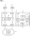
- the communication device 1 shown for an industrial communication network 2 that can be operated redundantly comprises a plurality of transmitting and receiving units 101-104, each of which has an interface for a network connection of the industrial communication network 2.
- a first and a second transmitting and receiving unit 101-102 are connected directly to the industrial communication network 2.
- a coupling element 12 is connected to the transmitting and receiving units 101-104.
- two simply connected network nodes 31-32 are connected to the first 101 and the second transmitting and receiving unit 102 via the coupling element 12.
- the coupling element 12 comprises a control unit 121 which is set up for the operation of virtual local networks.
- the coupling element 12 is preferably implemented by a backplane switch with an integrated controller.
- a signal processing unit 11 implemented by means of a field programmable gate array (FPGA) is assigned to the sending and receiving units 101-104 and comprises a replication unit 111 for duplicating messages to be sent redundantly by the first 101 and the second sending and receiving unit 102.
- the signal processing unit 11 has a filter unit 112 which is set up to detect messages redundantly received by the first 101 and the second transmitting and receiving unit 102. To each other redundant messages are identified by a common duplicate identifier.
- the communication device is designed and set up for operation in an industrial communication network 2 with a meshed network topology. For an at least partially redundant communication connection between two network nodes within the industrial communication network, mutually independent paths are determined which comprise separate network nodes of an individual communication network.
- the signal processing unit also includes a forwarding unit 113, which is designed and set up so that messages with duplicate identifiers are exchanged between the transmitting and receiving units 101-102 of the communication device 1, which are directly connected to the meshed communication network 2, in accordance with forwarding rules corresponding to the determined paths are.
- the forwarding unit 113 can also determine redundant, mutually independent paths in accordance with a possible embodiment variant or provide forwarding rules for communication devices at further network nodes within the industrial communication network 2.
- the signal processing unit 11 includes a memory unit 114 for storing duplicate identifiers of messages that have already been received without errors.
- the filter unit 112 is designed and set up to check its duplicate identifier for correspondence with an already stored duplicate identifier when a new message is received.
- the signal processing unit 11 includes a memory unit 115 for storing a table (proxy node table) with information about all of the simply connected network nodes 31-32 connected to the coupling element 12.
- the signal processing unit 11 comprises as an optional component a functional unit 116 which is designed and set up so that duplicate identifiers are inserted by the signal processing unit 11 into redundant messages of a simply connected network node 31-32.
- the signal processing unit 11 has as an optional component a functional unit 117 which is designed and set up so that duplicate identifiers are removed by the redundantly received messages for a simply connected network node 31-32 by the signal processing unit 11.
- the communication device accordingly Figure 1 is suitable for carrying out a method for redundant message transmission in an industrial communication network 2, in which the industrial communication network has a meshed network topology 2, and in which independent paths are determined for an at least partially redundant communication connection between two network nodes within the industrial communication network, which separate paths Include network nodes of a single communication network.
- the mutually independent paths can be determined both by a central instance within the industrial communication network and in a decentralized manner by the network nodes of the industrial communication network. For example, a virtual local network can be set up in each case for the mutually independent paths determined. The determined are accordingly independent of one another Identified paths based on an identifier of their assigned virtual local network.
- the network nodes 211-214 only implement the basic function FWD and exchange messages with duplicate identifiers according to forwarding rules corresponding to the determined paths between their connections.
- the basic function FWD can be implemented, for example, by switches without redundancy functions.
- the network nodes 201, 204 and 206 represent simply connected end nodes.
- the network node 201 in the present exemplary embodiment does not implement any redundancy functions, while the network nodes 204 and 206 at least implement the basic functions ADD and REM.
- the network node 202 serving as a branching point for the network node 201 realizes all of the above-mentioned basic functions.
- the network nodes 205 and 208 serving as branch points for the network nodes 204 and 206 only have to implement the basic functions CPY, FLT and FWD, since the two simply connected network nodes 204 and 206 already implement basic basic functions.
- network node 204 is connected directly to its assigned branching point.
- the network node 203 provides a duplicate to the in Figure 2 As a result of this, it implements all of the above-mentioned basic functions to carry out the above-described method for redundant message transmission.
Landscapes
- Engineering & Computer Science (AREA)
- Computer Networks & Wireless Communication (AREA)
- Signal Processing (AREA)
- Computer Security & Cryptography (AREA)
- Data Exchanges In Wide-Area Networks (AREA)
Claims (15)
- Procédé de transmission redondante de messages dans un réseau de communication industriel, dans lequel- au moins un appareil (1) de communication comprend au moins une première et une deuxième unités (101 à 104) d'émission et de réception, qui ont chacune une interface pour une liaison au réseau du réseau (2) de communication industriel et sont reliés à un élément (12) de couplage de l'appareil de communication,- aux unités d'émission et de réception est associée une unité (11) de traitement du signal de l'appareil de communication, par laquelle les messages à envoyer de manière redondante par l'appareil de communication sont envoyés dupliqués par les unités d'émission et de réception et des messages reçus de manière redondante par les unités d'émission et de réception sont détectés,- on caractérise des messages redondants entre eux par un identifiant commun de duplication,- le au moins un appareil de communication est un switch ou un bridge,caractérisé en ce que- le réseau de communication industriel a une topologie de réseau maillé à volonté, le réseau de communication comprenant respectivement plusieurs trajets, passant par des switches ou des bridges et des sections de couplage séparées, entre deux nœuds (202-203, 205, 208, 211-214) du réseau,- pour une liaison de communication, redondante au moins par partie, entre les deux nœuds de communication, on détermine dans le réseau de communication industriel des trajets indépendants l'un de l'autre, les trajets indépendants l'un de l'autre comprenant des nœuds de réseau séparés d'un réseau de communication individuel,- on échange des messages, entre les unités d'émission et de réception de l'appareil de communication, avec des règles d'acheminement correspondant aux trajets déterminés conformément aux identifiants de duplication.
- Procédé suivant la revendication 1,
dans lequel par l'élément de couplage, un nœud (31, 32) de réseau rattaché simplement, sans quelle que fonction de redondance que ce soit, est relié aux unités d'émission et de réception et dans lequel on insère dans des messages à envoyer de manière redondante des identifiants de duplication par le nœud de réseau rattaché simplement et dans lequel on retire des messages reçus de manière redondante des identifiants de duplication par le nœud de réseau rattaché simplement. - Procédé suivant la revendication 1,
dans lequel par l'élément de couplage, un nœud (31, 32) rattaché simplement, sans quelle que fonction de redondance que ce soit, est relié aux unités d'émission et de réception et dans lequel on insère dans des messages envoyer de manière redondante du nœud de réseau rattaché simplement des identifiants de duplication par l'unité de traitement du signal et dans lequel on retire des messages reçus de manière redondante, pour le nœud de réseau rattaché simplement, des identifiants de duplication par l'unité de traitement de signal. - Procédé suivant l'une des revendications 1 à 3,
dans lequel on établit pour les trajets indépendants l'un de l'autre, qui sont déterminés respectivement, un réseau local virtuel et dans lequel on identifie les trajets déterminés indépendants l'un de l'autre à l'aide d'une caractérisation de leur réseau local virtuel associé. - Procédé suivant l'une des revendications 1 à 4,
dans lequel on détermine les trajets indépendants l'un de l'autre par l'unité de traitement du signal. - Procédé suivant l'une des revendications 1 à 5,
dans lequel on détermine les trajets indépendants l'un de l'autre par une instance centrale dans le réseau de communication industriel. - Procédé suivant l'une des revendications 1 à 6, dans lequel on détermine les trajets indépendants l'un de l'autre de manière décentralisée par le nœud du réseau de communication industriel.
- Procédé suivant l'une des revendications 1 à 7, dans lequel dans une unité de mémoire associée à une unité de traitement du signal, on met en mémoire des identifiants de duplication d'un message reçu déjà sans erreur et dans lequel l'unité de traitement du signal contrôle, à la réception d'un nouveau message, son identifiant de duplication pour savoir s'il coïncide avec un identifiant de duplication déjà mis en mémoire.
- Appareil de communication pour un réseau de communication industriel pouvant fonctionner de manière redondante, comprenant- au moins une première et une deuxième unités d'émission et de réception, qui ont chacune une interface pour une liaison au réseau de communication industriel.- un élément (12) de couplage relié aux unités d'émission et de réception,- une unité (11) de traitement du signal, qui est associée aux unités d'émission et de réception et qui comprend une unité (111) de réplication pour dupliquer des messages à envoyer de manière redondante par les unités d'émission et de réception et une unité (112) de filtrage, qui est conçue pour détecter des messages reçus de manière redondante, dans lequel des messages redondants l'un par rapport à l'autre sont caractérisés par un identifiant de duplication commun,- dans lequel l'appareil de communication est un switch ou un bridge,caractérisé en ce que- l'appareil de communication est conformé et conçu pour un fonctionnement dans un réseau de communication industriel en ayant une topologie de réseau maillée à volonté, dans lequel pour une liaison de communication redondante au moins par endroit entre deux nœuds (202-203, 205, 208, 211-214) de réseau dans le réseau de communication industriel sont déterminés des trajets indépendants l'un de l'autre, qui comprennent des nœuds de réseaux séparés d'un réseau de communication individuel, dans lequel le réseau de communication comprend entre les deux nœuds de réseau respectivement plusieurs trajets passant par des switchs ou des bridges ou des sections de couplage séparées,- l'unité de traitement du signal comprend une unité (113) d'acheminement, qui est conformée et conçue pour échanger entre les unités d'émission et de réception de l'appareil de communication, des messages conformément à des règles d'acheminement correspondant aux trajets déterminés conformément à des identifiants de duplication.
- Appareil de communication suivant la revendication 9,
dans lequel dans l'élément de couplage un nœud (31, 32) de réseau rattaché simplement est relié, sans quelle que fonction de redondance que ce soit, aux unités d'émission et de réception et dans lequel l'unité de traitement du signal comprend une unité fonctionnelle, qui est conformée et conçue pour insérer, dans des messages envoyés de manière redondante des nœuds de réseau rattachés simplement, des identifiants de duplication par l'unité de traitement du signal et dans lequel l'unité de traitement du signal comprend une unité fonctionnelle qui est conformée et conçue pour retirer des messages reçus de manière redondante, pour le nœud de réseau rattaché simplement, des identifiants de duplication par l'unité de traitement de signal. - Appareil de communication suivant l'une des revendications 9 ou 10, dans lequel pour les trajets indépendants l'un de l'autre qui sont déterminés, est conçu respectivement un réseau local virtuel et dans lequel les trajets déterminés indépendants l'un de l'autre peuvent être identifiés à l'aide d'une caractérisation de leur réseau local virtuel associé et dans lequel l'élément de couplage comprend une unité de commande, qui est conçue pour le fonctionnement de réseau local virtuel.
- Appareil de communication suivant l'une des revendications 9 à 11, dans lequel l'unité de traitement du signal est conformée et conçue pour déterminer les trajets indépendants l'un de l'autre.
- Appareil de communication suivant l'une des revendications 9 à 12, dans lequel les unités d'émission et de réception sont reliées à l'élément de couplage directement ou par l'unité de traitement du signal.
- Appareil de communication suivant l'une des revendications 9 à 13, dans lequel l'unité de traitement du signal est reliée aux unités d'émission et de réception directement ou par l'élément de couplage.
- Appareil de communication suivant l'une des revendications 9 à 14, dans lequel l'unité de traitement du signal comprend une unité (114) de mémoire pour la mise en mémoire d'identifiants de duplication de messages reçus déjà sans erreur et dans lequel l'unité de filtrage est conformée et conçue pour contrôler à la réception d'un message nouveau son identifiant de duplication, pour savoir s'il coïncide avec un identifiant de duplication déjà mis en mémoire.
Priority Applications (3)
| Application Number | Priority Date | Filing Date | Title |
|---|---|---|---|
| EP13180335.5A EP2838220B1 (fr) | 2013-08-14 | 2013-08-14 | Procédé de transmission redondante de messages dans un réseau de communication industriel et appareil de communication |
| US14/458,869 US9673995B2 (en) | 2013-08-14 | 2014-08-13 | Communication device and method for redundant message transmission in an industrial communication network |
| CN201410406017.7A CN104378291B (zh) | 2013-08-14 | 2014-08-14 | 用于在工业通信网络中进行冗余的信息传输的方法和通信设备 |
Applications Claiming Priority (1)
| Application Number | Priority Date | Filing Date | Title |
|---|---|---|---|
| EP13180335.5A EP2838220B1 (fr) | 2013-08-14 | 2013-08-14 | Procédé de transmission redondante de messages dans un réseau de communication industriel et appareil de communication |
Publications (2)
| Publication Number | Publication Date |
|---|---|
| EP2838220A1 EP2838220A1 (fr) | 2015-02-18 |
| EP2838220B1 true EP2838220B1 (fr) | 2021-09-29 |
Family
ID=48998448
Family Applications (1)
| Application Number | Title | Priority Date | Filing Date |
|---|---|---|---|
| EP13180335.5A Active EP2838220B1 (fr) | 2013-08-14 | 2013-08-14 | Procédé de transmission redondante de messages dans un réseau de communication industriel et appareil de communication |
Country Status (3)
| Country | Link |
|---|---|
| US (1) | US9673995B2 (fr) |
| EP (1) | EP2838220B1 (fr) |
| CN (1) | CN104378291B (fr) |
Cited By (1)
| Publication number | Priority date | Publication date | Assignee | Title |
|---|---|---|---|---|
| EP4718786A1 (fr) | 2024-09-25 | 2026-04-01 | Siemens Aktiengesellschaft | Procédé de transmission redondante de données dans un réseau de communication, système de communication et dispositif de configuration |
Families Citing this family (22)
| Publication number | Priority date | Publication date | Assignee | Title |
|---|---|---|---|---|
| EP3286898B1 (fr) * | 2015-04-21 | 2021-03-03 | Google LLC | Messagerie sur canaux multiples |
| KR101655680B1 (ko) * | 2015-05-29 | 2016-09-08 | (주)앱스톤 | Hsr 기반한 고가용성 네트워크 장치 |
| WO2016193443A1 (fr) * | 2015-06-03 | 2016-12-08 | Hirschmann Automation And Control Gmbh | Procédé pour un système de transmission redondant à prp et stockage intermédiaire de paquets de données |
| US10156841B2 (en) | 2015-12-31 | 2018-12-18 | General Electric Company | Identity management and device enrollment in a cloud service |
| CN109314655B (zh) | 2016-06-10 | 2021-12-28 | Tt柔性技术有限公司 | 在将节点连接到通信网络的冗余端口处接收帧的方法和装置 |
| EP3343303B1 (fr) * | 2016-12-29 | 2019-06-26 | Siemens Aktiengesellschaft | Système de radiocommunication pour un système d'automatisation industrielle et son procédé de fonctionnement |
| WO2018177537A1 (fr) | 2017-03-31 | 2018-10-04 | Siemens Aktiengesellschaft | Procédé d'exploitation d'un réseau de communication comportant plusieurs appareils de communication pour un système industriel d'automatisation et unité de commande |
| DE102017218460A1 (de) * | 2017-10-16 | 2019-04-18 | Siemens Aktiengesellschaft | Bahnautomatisierungsnetz sowie Verfahren zum Übermitteln von Nachrichten in einem Bahnautomatisierungsnetz |
| EP3598254B1 (fr) * | 2018-07-17 | 2021-03-31 | Siemens Aktiengesellschaft | Procédé de changement de configuration et système d'installations industriel |
| DE102019205634A1 (de) * | 2019-04-17 | 2020-10-22 | Robert Bosch Gmbh | Verfahren zum Betreiben von TSN-fähigen Netzwerkkopplungselementen |
| US11159435B2 (en) * | 2019-11-07 | 2021-10-26 | Abb Schweiz Ag | Time-sensitive networking for industrial automation |
| CN114846777B (zh) * | 2019-11-11 | 2023-10-24 | 西门子加拿大有限公司 | 用于在工业网络中提供冗余的网络设备 |
| EP3846395A1 (fr) | 2019-12-30 | 2021-07-07 | Siemens Aktiengesellschaft | Procédé de transmission redondante des flux de données dans un réseau de communication, appareil d'infrastructure de réseau et terminal de communication |
| CN112187607B (zh) * | 2020-10-20 | 2022-03-11 | 南京科远智慧科技集团股份有限公司 | 一种应用于控制系统通信扩展的系统 |
| EP4006659A1 (fr) | 2020-11-25 | 2022-06-01 | Siemens Aktiengesellschaft | Terminal |
| KR102511640B1 (ko) * | 2021-01-15 | 2023-03-17 | 명지대학교 산학협력단 | 에이치에스알 프로토콜을 사용하는 차량 내부 네크워크 및 이의 설계 방법 |
| EP4054143A1 (fr) * | 2021-03-02 | 2022-09-07 | Siemens Aktiengesellschaft | Authentification d'un appareil dans un réseau de communication d'une installation d'automatisation |
| EP4060946A1 (fr) | 2021-03-16 | 2022-09-21 | Siemens Aktiengesellschaft | Authentification d'un appareil dans un réseau de communication d'une installation d'automatisation |
| US11336564B1 (en) * | 2021-09-01 | 2022-05-17 | Schweitzer Engineering Laboratories, Inc. | Detection of active hosts using parallel redundancy protocol in software defined networks |
| CN116339179A (zh) * | 2021-12-24 | 2023-06-27 | 中国科学院沈阳自动化研究所 | 一种用于高速工业以太网介质冗余的方法 |
| CN114915386B (zh) * | 2022-04-29 | 2023-10-13 | 中国航空无线电电子研究所 | 面向差异化业务场景的确定性通信的冗余传输管理方法 |
| CN116319156A (zh) * | 2023-03-07 | 2023-06-23 | 西门子(中国)有限公司 | 工业网络系统 |
Family Cites Families (6)
| Publication number | Priority date | Publication date | Assignee | Title |
|---|---|---|---|---|
| US7188189B2 (en) * | 2003-04-02 | 2007-03-06 | Avaya Technology Corp. | System and method to improve the resiliency and performance of enterprise networks by utilizing in-built network redundancy |
| US7590756B2 (en) * | 2005-05-13 | 2009-09-15 | Itt Manufacturing Enterprises, Inc. | Method and system for transferring data in a communications network using redundant communication paths |
| CN101682555B (zh) | 2007-07-05 | 2016-02-03 | 赫思曼自动化控制有限公司 | 网络的快速环冗余 |
| US8280057B2 (en) * | 2007-09-04 | 2012-10-02 | Honeywell International Inc. | Method and apparatus for providing security in wireless communication networks |
| EP2282452B1 (fr) | 2009-07-31 | 2012-04-04 | ABB Research Ltd. | Transmission de données dans un réseau de communication de type anneau |
| ES2411081T3 (es) | 2010-07-30 | 2013-07-04 | Siemens Aktiengesellschaft | Prevención de bucles de transmisión en una red en anillo redundante |
-
2013
- 2013-08-14 EP EP13180335.5A patent/EP2838220B1/fr active Active
-
2014
- 2014-08-13 US US14/458,869 patent/US9673995B2/en active Active
- 2014-08-14 CN CN201410406017.7A patent/CN104378291B/zh active Active
Cited By (2)
| Publication number | Priority date | Publication date | Assignee | Title |
|---|---|---|---|---|
| EP4718786A1 (fr) | 2024-09-25 | 2026-04-01 | Siemens Aktiengesellschaft | Procédé de transmission redondante de données dans un réseau de communication, système de communication et dispositif de configuration |
| WO2026068126A1 (fr) | 2024-09-25 | 2026-04-02 | Siemens Aktiengesellschaft | Procédé d'émission de données redondante dans un réseau de communication, système de communication et dispositif de configuration |
Also Published As
| Publication number | Publication date |
|---|---|
| CN104378291A (zh) | 2015-02-25 |
| CN104378291B (zh) | 2018-08-07 |
| US9673995B2 (en) | 2017-06-06 |
| US20150049639A1 (en) | 2015-02-19 |
| EP2838220A1 (fr) | 2015-02-18 |
Similar Documents
| Publication | Publication Date | Title |
|---|---|---|
| EP2838220B1 (fr) | Procédé de transmission redondante de messages dans un réseau de communication industriel et appareil de communication | |
| EP2688249B1 (fr) | Procédé de transmission de nouvelles dans un réseau de communication industriel pouvant fonctionner de manière redondante et appareil de communication pour un réseau de communication industriel pouvant fonctionner de manière redondante | |
| EP2693700B1 (fr) | Procédé de transmission de messages dans un réseau de communication industriel pouvant fonctionner de manière redondante et appareil de communication pour un réseau de communication industriel pouvant fonctionner de manière redondante | |
| EP2634973B1 (fr) | Appareil de communication pour un réseau de communication industriel fonctionnant de manière redondante et procédé de fonctionnement d'un appareil de communication | |
| EP2302841B1 (fr) | Procédé et dispositif de communication orientée vers la sécurité dans le réseau de communication d'une installation d'automatisation | |
| EP2661023B1 (fr) | Appareil de communication pour un réseau de communication industriel fonctionnant de manière redondante et procédé de fonctionnement d'un appareil de communication | |
| EP2343857B1 (fr) | Noeud de réseau pour un réseau de communication | |
| EP2034668B1 (fr) | Système de communication hautement disponible | |
| EP3547618B1 (fr) | Procédé d'établissement d'une connexion de communication redondante et unité de commande sécurisée | |
| EP2713563B1 (fr) | Système de communication industriel pouvant fonctionner de manière redondante, appareil de communication et procédé de fonctionnement redondant d'un système de communication industriel | |
| EP3017570B1 (fr) | Dispositif de controle, noeud de reseau et procede pour l'echange des donnees sur un reseau | |
| EP3151476B1 (fr) | Procede de trafic transversal entre deux esclaves d'un reseau de donnees en boucle | |
| EP3691207A1 (fr) | Procédé de fonctionnement d'un système de communication doté de routeurs redondants et routeurs | |
| EP2913727B1 (fr) | Procédé de transmission de messages via un système bus de fond de panier d'un automate industriel modulaire | |
| EP3628078B1 (fr) | Procédé de fonctionnement d'un réseau de communication comprenant plusieurs appareils de communication d'un système d'automatisation industriel et organe de commande | |
| EP3787237A1 (fr) | Procédé de transmission de données dans un réseau de communication à fonctionnement redondant et appareil de communication par couplage | |
| EP3142296B1 (fr) | Procede de configuration d'un appareil de commande modulaire d'un systeme d'automatisation industriel et appareil de commande modulaire | |
| EP2680503B1 (fr) | Appareil de communication pour un réseau de communication industriel fonctionnant de manière redondante et procédé de fonctionnement d'un appareil de communication | |
| EP2704370B1 (fr) | Procédé de transmission de nouvelles dans un réseau de communication industriel pouvant fonctionner de manière redondante et appareil de communication pour un réseau de communication industriel pouvant fonctionner de manière redondante | |
| EP2670078B1 (fr) | Appareil de communication pour un réseau de communication industriel fonctionnant de manière redondante et procédé de fonctionnement d'un appareil de communication | |
| EP3343303B1 (fr) | Système de radiocommunication pour un système d'automatisation industrielle et son procédé de fonctionnement | |
| EP4125253B1 (fr) | Procédé de transmission de données temporellement critiques, système de communication et appareil de communication couplée | |
| EP2750310A1 (fr) | Procédé de synchronisation d'horloges locales dans un réseau de communication d'un système d'automatisation industriel et appareil d'infrastructure de réseau | |
| EP3457232B1 (fr) | Procédé de fonctionnement d'un système d'automatisation à haute disponibilité | |
| EP3435179B1 (fr) | Procédé d'échange fonctionnel sécurisé d'informations conforme à une norme de sécurité |
Legal Events
| Date | Code | Title | Description |
|---|---|---|---|
| 17P | Request for examination filed |
Effective date: 20130814 |
|
| AK | Designated contracting states |
Kind code of ref document: A1 Designated state(s): AL AT BE BG CH CY CZ DE DK EE ES FI FR GB GR HR HU IE IS IT LI LT LU LV MC MK MT NL NO PL PT RO RS SE SI SK SM TR |
|
| AX | Request for extension of the european patent |
Extension state: BA ME |
|
| PUAI | Public reference made under article 153(3) epc to a published international application that has entered the european phase |
Free format text: ORIGINAL CODE: 0009012 |
|
| R17P | Request for examination filed (corrected) |
Effective date: 20150818 |
|
| RBV | Designated contracting states (corrected) |
Designated state(s): AL AT BE BG CH CY CZ DE DK EE ES FI FR GB GR HR HU IE IS IT LI LT LU LV MC MK MT NL NO PL PT RO RS SE SI SK SM TR |
|
| RAP1 | Party data changed (applicant data changed or rights of an application transferred) |
Owner name: SIEMENS AKTIENGESELLSCHAFT |
|
| STAA | Information on the status of an ep patent application or granted ep patent |
Free format text: STATUS: EXAMINATION IS IN PROGRESS |
|
| 17Q | First examination report despatched |
Effective date: 20190909 |
|
| GRAP | Despatch of communication of intention to grant a patent |
Free format text: ORIGINAL CODE: EPIDOSNIGR1 |
|
| STAA | Information on the status of an ep patent application or granted ep patent |
Free format text: STATUS: GRANT OF PATENT IS INTENDED |
|
| INTG | Intention to grant announced |
Effective date: 20210428 |
|
| GRAS | Grant fee paid |
Free format text: ORIGINAL CODE: EPIDOSNIGR3 |
|
| GRAA | (expected) grant |
Free format text: ORIGINAL CODE: 0009210 |
|
| STAA | Information on the status of an ep patent application or granted ep patent |
Free format text: STATUS: THE PATENT HAS BEEN GRANTED |
|
| AK | Designated contracting states |
Kind code of ref document: B1 Designated state(s): AL AT BE BG CH CY CZ DE DK EE ES FI FR GB GR HR HU IE IS IT LI LT LU LV MC MK MT NL NO PL PT RO RS SE SI SK SM TR |
|
| REG | Reference to a national code |
Ref country code: GB Ref legal event code: FG4D Free format text: NOT ENGLISH |
|
| REG | Reference to a national code |
Ref country code: DE Ref legal event code: R096 Ref document number: 502013015943 Country of ref document: DE |
|
| REG | Reference to a national code |
Ref country code: CH Ref legal event code: EP Ref country code: AT Ref legal event code: REF Ref document number: 1435156 Country of ref document: AT Kind code of ref document: T Effective date: 20211015 |
|
| REG | Reference to a national code |
Ref country code: IE Ref legal event code: FG4D Free format text: LANGUAGE OF EP DOCUMENT: GERMAN |
|
| REG | Reference to a national code |
Ref country code: LT Ref legal event code: MG9D |
|
| PG25 | Lapsed in a contracting state [announced via postgrant information from national office to epo] |
Ref country code: SE Free format text: LAPSE BECAUSE OF FAILURE TO SUBMIT A TRANSLATION OF THE DESCRIPTION OR TO PAY THE FEE WITHIN THE PRESCRIBED TIME-LIMIT Effective date: 20210929 Ref country code: HR Free format text: LAPSE BECAUSE OF FAILURE TO SUBMIT A TRANSLATION OF THE DESCRIPTION OR TO PAY THE FEE WITHIN THE PRESCRIBED TIME-LIMIT Effective date: 20210929 Ref country code: BG Free format text: LAPSE BECAUSE OF FAILURE TO SUBMIT A TRANSLATION OF THE DESCRIPTION OR TO PAY THE FEE WITHIN THE PRESCRIBED TIME-LIMIT Effective date: 20211229 Ref country code: LT Free format text: LAPSE BECAUSE OF FAILURE TO SUBMIT A TRANSLATION OF THE DESCRIPTION OR TO PAY THE FEE WITHIN THE PRESCRIBED TIME-LIMIT Effective date: 20210929 Ref country code: NO Free format text: LAPSE BECAUSE OF FAILURE TO SUBMIT A TRANSLATION OF THE DESCRIPTION OR TO PAY THE FEE WITHIN THE PRESCRIBED TIME-LIMIT Effective date: 20211229 Ref country code: RS Free format text: LAPSE BECAUSE OF FAILURE TO SUBMIT A TRANSLATION OF THE DESCRIPTION OR TO PAY THE FEE WITHIN THE PRESCRIBED TIME-LIMIT Effective date: 20210929 Ref country code: FI Free format text: LAPSE BECAUSE OF FAILURE TO SUBMIT A TRANSLATION OF THE DESCRIPTION OR TO PAY THE FEE WITHIN THE PRESCRIBED TIME-LIMIT Effective date: 20210929 |
|
| REG | Reference to a national code |
Ref country code: NL Ref legal event code: MP Effective date: 20210929 |
|
| PG25 | Lapsed in a contracting state [announced via postgrant information from national office to epo] |
Ref country code: LV Free format text: LAPSE BECAUSE OF FAILURE TO SUBMIT A TRANSLATION OF THE DESCRIPTION OR TO PAY THE FEE WITHIN THE PRESCRIBED TIME-LIMIT Effective date: 20210929 Ref country code: GR Free format text: LAPSE BECAUSE OF FAILURE TO SUBMIT A TRANSLATION OF THE DESCRIPTION OR TO PAY THE FEE WITHIN THE PRESCRIBED TIME-LIMIT Effective date: 20211230 |
|
| PG25 | Lapsed in a contracting state [announced via postgrant information from national office to epo] |
Ref country code: IS Free format text: LAPSE BECAUSE OF FAILURE TO SUBMIT A TRANSLATION OF THE DESCRIPTION OR TO PAY THE FEE WITHIN THE PRESCRIBED TIME-LIMIT Effective date: 20220129 Ref country code: SK Free format text: LAPSE BECAUSE OF FAILURE TO SUBMIT A TRANSLATION OF THE DESCRIPTION OR TO PAY THE FEE WITHIN THE PRESCRIBED TIME-LIMIT Effective date: 20210929 Ref country code: RO Free format text: LAPSE BECAUSE OF FAILURE TO SUBMIT A TRANSLATION OF THE DESCRIPTION OR TO PAY THE FEE WITHIN THE PRESCRIBED TIME-LIMIT Effective date: 20210929 Ref country code: PT Free format text: LAPSE BECAUSE OF FAILURE TO SUBMIT A TRANSLATION OF THE DESCRIPTION OR TO PAY THE FEE WITHIN THE PRESCRIBED TIME-LIMIT Effective date: 20220131 Ref country code: PL Free format text: LAPSE BECAUSE OF FAILURE TO SUBMIT A TRANSLATION OF THE DESCRIPTION OR TO PAY THE FEE WITHIN THE PRESCRIBED TIME-LIMIT Effective date: 20210929 Ref country code: NL Free format text: LAPSE BECAUSE OF FAILURE TO SUBMIT A TRANSLATION OF THE DESCRIPTION OR TO PAY THE FEE WITHIN THE PRESCRIBED TIME-LIMIT Effective date: 20210929 Ref country code: ES Free format text: LAPSE BECAUSE OF FAILURE TO SUBMIT A TRANSLATION OF THE DESCRIPTION OR TO PAY THE FEE WITHIN THE PRESCRIBED TIME-LIMIT Effective date: 20210929 Ref country code: EE Free format text: LAPSE BECAUSE OF FAILURE TO SUBMIT A TRANSLATION OF THE DESCRIPTION OR TO PAY THE FEE WITHIN THE PRESCRIBED TIME-LIMIT Effective date: 20210929 Ref country code: CZ Free format text: LAPSE BECAUSE OF FAILURE TO SUBMIT A TRANSLATION OF THE DESCRIPTION OR TO PAY THE FEE WITHIN THE PRESCRIBED TIME-LIMIT Effective date: 20210929 Ref country code: AL Free format text: LAPSE BECAUSE OF FAILURE TO SUBMIT A TRANSLATION OF THE DESCRIPTION OR TO PAY THE FEE WITHIN THE PRESCRIBED TIME-LIMIT Effective date: 20210929 |
|
| REG | Reference to a national code |
Ref country code: DE Ref legal event code: R097 Ref document number: 502013015943 Country of ref document: DE |
|
| PG25 | Lapsed in a contracting state [announced via postgrant information from national office to epo] |
Ref country code: DK Free format text: LAPSE BECAUSE OF FAILURE TO SUBMIT A TRANSLATION OF THE DESCRIPTION OR TO PAY THE FEE WITHIN THE PRESCRIBED TIME-LIMIT Effective date: 20210929 |
|
| PLBE | No opposition filed within time limit |
Free format text: ORIGINAL CODE: 0009261 |
|
| STAA | Information on the status of an ep patent application or granted ep patent |
Free format text: STATUS: NO OPPOSITION FILED WITHIN TIME LIMIT |
|
| 26N | No opposition filed |
Effective date: 20220630 |
|
| PG25 | Lapsed in a contracting state [announced via postgrant information from national office to epo] |
Ref country code: SI Free format text: LAPSE BECAUSE OF FAILURE TO SUBMIT A TRANSLATION OF THE DESCRIPTION OR TO PAY THE FEE WITHIN THE PRESCRIBED TIME-LIMIT Effective date: 20210929 |
|
| PG25 | Lapsed in a contracting state [announced via postgrant information from national office to epo] |
Ref country code: MC Free format text: LAPSE BECAUSE OF FAILURE TO SUBMIT A TRANSLATION OF THE DESCRIPTION OR TO PAY THE FEE WITHIN THE PRESCRIBED TIME-LIMIT Effective date: 20210929 |
|
| REG | Reference to a national code |
Ref country code: CH Ref legal event code: PL |
|
| GBPC | Gb: european patent ceased through non-payment of renewal fee |
Effective date: 20220814 |
|
| PG25 | Lapsed in a contracting state [announced via postgrant information from national office to epo] |
Ref country code: LU Free format text: LAPSE BECAUSE OF NON-PAYMENT OF DUE FEES Effective date: 20220814 Ref country code: LI Free format text: LAPSE BECAUSE OF NON-PAYMENT OF DUE FEES Effective date: 20220831 Ref country code: CH Free format text: LAPSE BECAUSE OF NON-PAYMENT OF DUE FEES Effective date: 20220831 |
|
| REG | Reference to a national code |
Ref country code: BE Ref legal event code: MM Effective date: 20220831 |
|
| P01 | Opt-out of the competence of the unified patent court (upc) registered |
Effective date: 20230510 |
|
| PG25 | Lapsed in a contracting state [announced via postgrant information from national office to epo] |
Ref country code: IE Free format text: LAPSE BECAUSE OF NON-PAYMENT OF DUE FEES Effective date: 20220814 |
|
| PG25 | Lapsed in a contracting state [announced via postgrant information from national office to epo] |
Ref country code: BE Free format text: LAPSE BECAUSE OF NON-PAYMENT OF DUE FEES Effective date: 20220831 |
|
| REG | Reference to a national code |
Ref country code: AT Ref legal event code: MM01 Ref document number: 1435156 Country of ref document: AT Kind code of ref document: T Effective date: 20220814 |
|
| PG25 | Lapsed in a contracting state [announced via postgrant information from national office to epo] |
Ref country code: GB Free format text: LAPSE BECAUSE OF NON-PAYMENT OF DUE FEES Effective date: 20220814 Ref country code: AT Free format text: LAPSE BECAUSE OF NON-PAYMENT OF DUE FEES Effective date: 20220814 |
|
| PG25 | Lapsed in a contracting state [announced via postgrant information from national office to epo] |
Ref country code: HU Free format text: LAPSE BECAUSE OF FAILURE TO SUBMIT A TRANSLATION OF THE DESCRIPTION OR TO PAY THE FEE WITHIN THE PRESCRIBED TIME-LIMIT; INVALID AB INITIO Effective date: 20130814 |
|
| PG25 | Lapsed in a contracting state [announced via postgrant information from national office to epo] |
Ref country code: SM Free format text: LAPSE BECAUSE OF FAILURE TO SUBMIT A TRANSLATION OF THE DESCRIPTION OR TO PAY THE FEE WITHIN THE PRESCRIBED TIME-LIMIT Effective date: 20210929 Ref country code: CY Free format text: LAPSE BECAUSE OF FAILURE TO SUBMIT A TRANSLATION OF THE DESCRIPTION OR TO PAY THE FEE WITHIN THE PRESCRIBED TIME-LIMIT Effective date: 20210929 |
|
| PG25 | Lapsed in a contracting state [announced via postgrant information from national office to epo] |
Ref country code: MK Free format text: LAPSE BECAUSE OF FAILURE TO SUBMIT A TRANSLATION OF THE DESCRIPTION OR TO PAY THE FEE WITHIN THE PRESCRIBED TIME-LIMIT Effective date: 20210929 |
|
| PG25 | Lapsed in a contracting state [announced via postgrant information from national office to epo] |
Ref country code: TR Free format text: LAPSE BECAUSE OF FAILURE TO SUBMIT A TRANSLATION OF THE DESCRIPTION OR TO PAY THE FEE WITHIN THE PRESCRIBED TIME-LIMIT Effective date: 20210929 |
|
| PG25 | Lapsed in a contracting state [announced via postgrant information from national office to epo] |
Ref country code: MT Free format text: LAPSE BECAUSE OF FAILURE TO SUBMIT A TRANSLATION OF THE DESCRIPTION OR TO PAY THE FEE WITHIN THE PRESCRIBED TIME-LIMIT Effective date: 20210929 |
|
| PGFP | Annual fee paid to national office [announced via postgrant information from national office to epo] |
Ref country code: IT Payment date: 20250827 Year of fee payment: 13 |
|
| PGFP | Annual fee paid to national office [announced via postgrant information from national office to epo] |
Ref country code: FR Payment date: 20250827 Year of fee payment: 13 |
|
| PGFP | Annual fee paid to national office [announced via postgrant information from national office to epo] |
Ref country code: DE Payment date: 20251020 Year of fee payment: 13 |