EP2838227A1 - Verfahren, vorrichtung und system zur konnektivitätserkennung - Google Patents
Verfahren, vorrichtung und system zur konnektivitätserkennung Download PDFInfo
- Publication number
- EP2838227A1 EP2838227A1 EP20120877586 EP12877586A EP2838227A1 EP 2838227 A1 EP2838227 A1 EP 2838227A1 EP 20120877586 EP20120877586 EP 20120877586 EP 12877586 A EP12877586 A EP 12877586A EP 2838227 A1 EP2838227 A1 EP 2838227A1
- Authority
- EP
- European Patent Office
- Prior art keywords
- node
- hop count
- source node
- target nodes
- request information
- Prior art date
- Legal status (The legal status is an assumption and is not a legal conclusion. Google has not performed a legal analysis and makes no representation as to the accuracy of the status listed.)
- Withdrawn
Links
- 238000001514 detection method Methods 0.000 title claims abstract description 241
- 238000000034 method Methods 0.000 claims abstract description 81
- 238000012545 processing Methods 0.000 claims abstract description 27
- 238000003745 diagnosis Methods 0.000 abstract description 14
- 238000005516 engineering process Methods 0.000 abstract description 5
- 238000004891 communication Methods 0.000 abstract description 2
- 230000008569 process Effects 0.000 description 24
- 238000010586 diagram Methods 0.000 description 18
- 238000012360 testing method Methods 0.000 description 7
- 230000006870 function Effects 0.000 description 4
- 235000008694 Humulus lupulus Nutrition 0.000 description 3
- 238000002955 isolation Methods 0.000 description 2
- 238000012423 maintenance Methods 0.000 description 2
- 230000009286 beneficial effect Effects 0.000 description 1
- 230000005540 biological transmission Effects 0.000 description 1
- 230000006872 improvement Effects 0.000 description 1
- 238000012986 modification Methods 0.000 description 1
- 230000004048 modification Effects 0.000 description 1
- 230000003287 optical effect Effects 0.000 description 1
Images




Classifications
-
- H—ELECTRICITY
- H04—ELECTRIC COMMUNICATION TECHNIQUE
- H04L—TRANSMISSION OF DIGITAL INFORMATION, e.g. TELEGRAPHIC COMMUNICATION
- H04L43/00—Arrangements for monitoring or testing data switching networks
- H04L43/08—Monitoring or testing based on specific metrics, e.g. QoS, energy consumption or environmental parameters
- H04L43/0805—Monitoring or testing based on specific metrics, e.g. QoS, energy consumption or environmental parameters by checking availability
- H04L43/0811—Monitoring or testing based on specific metrics, e.g. QoS, energy consumption or environmental parameters by checking availability by checking connectivity
-
- H—ELECTRICITY
- H04—ELECTRIC COMMUNICATION TECHNIQUE
- H04L—TRANSMISSION OF DIGITAL INFORMATION, e.g. TELEGRAPHIC COMMUNICATION
- H04L12/00—Data switching networks
- H04L12/02—Details
- H04L12/16—Arrangements for providing special services to substations
- H04L12/18—Arrangements for providing special services to substations for broadcast or conference, e.g. multicast
- H04L12/1863—Arrangements for providing special services to substations for broadcast or conference, e.g. multicast comprising mechanisms for improved reliability, e.g. status reports
-
- H—ELECTRICITY
- H04—ELECTRIC COMMUNICATION TECHNIQUE
- H04L—TRANSMISSION OF DIGITAL INFORMATION, e.g. TELEGRAPHIC COMMUNICATION
- H04L45/00—Routing or path finding of packets in data switching networks
- H04L45/20—Hop count for routing purposes, e.g. TTL
-
- H—ELECTRICITY
- H04—ELECTRIC COMMUNICATION TECHNIQUE
- H04L—TRANSMISSION OF DIGITAL INFORMATION, e.g. TELEGRAPHIC COMMUNICATION
- H04L45/00—Routing or path finding of packets in data switching networks
- H04L45/28—Routing or path finding of packets in data switching networks using route fault recovery
Definitions
- the present invention relates to the field of communications technologies, and in particular, to a method, an apparatus, and a system for detecting connectivity.
- TRILL Transparent Interconnection of Lots of Links
- TRILL Transparent Interconnection of Lots of Links in English, TRILL for short
- TRILL technology runs at a data link layer (Layer 2), and mainly integrates advantages of a bridge and a router, that is, a link state routing (Link State Routing in English) technology is used at the data link layer, and does not interfere with operation of an upper-layer router.
- a packet header of a TRILL packet is shown in FIG. 1 , where an egress routing bridge nickname (Egress RBridge Nickname in English) is used to store a nickname of a target routing bridge during unicasting and is used to store a multicast distribution tree nickname (multicast distribution tree nickname) during multicasting; an ingress routing bridge nickname (Ingress RBridge Nickname in English) is used to store a nickname of a source routing bridge; and a hop count (Hop count in English) is the number of times that the TRILL packet may be forwarded to a next hop during a propagation process.
- Egress RBridge Nickname in English is used to store a nickname of a target routing bridge during unicasting and is used to store a multicast distribution tree nickname (multicast distribution tree nickname) during multicasting
- an ingress routing bridge nickname Ingress RBridge Nickname in English
- a hop count Hop count in English
- Operation, administration and maintenance (Operation Administration and Maintenance in English, OAM for short) generally includes connectivity detection, error isolation, and fault diagnosis between two nodes, while OAM using the TRILL technology has become a main means to perform connectivity detection, error isolation, and fault diagnosis between two nodes.
- FIG. 2 is a schematic diagram of testing a multicast path by using traceroute in the prior art.
- Ovals numbered 1, 2, 3, 4, 5, 6, and 7 in FIG. 2 represent a routing bridge RB1, a routing bridge RB2, a routing bridge RB3, a routing bridge RB4, a routing bridge RB5, a routing bridge RB6, and a routing bridge RB7 respectively. If a multicast distribution tree tree 1 using the routing bridge RB2 as a root (root) is established in an entire topology, and for the multicast distribution tree tree1, reference may be made to bold lines in FIG.
- traceroute may be performed on the tree1 on the source node routing bridge RB1.
- a specific traceroute process is as follows: The routing bridge RB 1 sends a multicast packet of which an ingress routing bridge nickname is RB 1 and an egress routing bridge nickname is tree1; the multicast packet includes connectivity detection request information (echo request in English); therefore, the connectivity detection request information is multicast with the packet on a network formed by the routing bridges.
- the routing bridge RB1 first sets a hop count (Hop count in English) in the connectivity detection request information to 1, and increases the hop count gradually each time the routing bridge RB 1 sends the connectivity detection request information until the hop count reaches a maximum value.
- the connectivity detection request information may be carried in an OAM packet for forwarding.
- a packet header of the OAM packet here, reference may be made to FIG. 1 . So long as the value of the hop count is large enough, the connectivity detection request information is copied and forwarded (as shown by arrows in FIG. 2 ) with the multicast packet along the tree1.
- the routing bridge RB1 first forwards the connectivity detection request information to the routing bridge RB7 and the routing bridge RB5 in the distribution tree tree1; after receiving the packet, the routing bridge RB7 and the routing bridge RB5 deducts the hop count in the received connectivity detection request information by 1, and the hop count becomes 0.
- the routing bridge RB7 Because the routing bridge RB7 is a leaf node, the routing bridge RB7 sends connectivity detection reply information (echo reply) to the routing bridge RB1, while the routing bridge RB5 sends unreachable information (error) to the routing bridge RB1, and stops further forwarding.
- connectivity detection reply information echo reply
- unreachable information error
- the routing bridge RB1 After receiving the unreachable information returned by the routing bridge RB5, the routing bridge RB1 adds 1 to the hop count, and continues to send a connectivity detection request information of which a hop count is 2 to the routing bridge RB7 and the routing bridge RB5 through multicasting; after receiving the multicast packet, the routing bridge RB5 deducts the hop count by 1, and the hop count becomes 1, and then the routing bridge RB5 continues to forward the multicast packet to the routing bridge RB2 along the tree 1; after receiving the multicast packet, the routing bridge RB2 deducts the hop count by 1, and the hop count becomes 0, and then the routing bridge RB2 sends unreachable information to the routing bridge RB 1. The rest is deduced by analogy.
- the routing bridge RB1 Each time the routing bridge RB1 receives latest unreachable information, it increases the hop count until the hop count reaches a maximum value. As the hop count increases, the routing bridge RB1 obtains unreachable information sent by nodes which are one hop, two hops, three hops...n hops away from the routing bridge RB1 in sequence, and the unreachable information carries information about the nodes that send the unreachable information. In addition, during the foregoing multicast process, the RB1 receives connectivity detection reply information sent by the RB7, the RB3, and the RB4 respectively. In this way, the RB1 may depict a structure of the entire tree according to the received unreachable information.
- embodiments of the present invention provide a method, an apparatus, and a system for detecting connectivity.
- the technical solutions are as follows:
- An apparatus for detecting connectivity includes:
- a system for detecting connectivity includes the foregoing apparatus for detecting connectivity.
- FIG. 3A shows a schematic diagram of an implementation environment of a method for detecting connectivity according to an embodiment of the present invention.
- the implementation environment includes a source node routing bridge 310A and several non-source node routing bridges 320A, and connectivity detection request information may be sent by the source node routing bridge to one or some of the non-source node routing bridges according to a rule, and may be forwarded between the non-source node routing bridges according to a predetermined rule.
- the source node routing bridge 310A may serve as a start node of a designated path in a designated multicast distribution tree during multicasting of the connectivity detection request information, and the source node routing bridge 310A may send the connectivity detection request information to a routing bridge on another node.
- the non-source node routing bridges 320A may serve as routing bridges that receive and/or forward the connectivity detection request information during the multicasting of the connectivity detection request information.
- the designated path in the multicast distribution tree generally includes a plurality of non-source node routing bridges 320A that is connected in sequence. As shown in FIG.
- the source node routing bridge 310A, a non-source node routing bridge 321A, a non-source node routing bridge 322A...a non-source node routing bridge 323A, and a non-source node routing bridge 324A are connected in sequence to form the designated path in the designated multicast distribution tree; a multicast packet (that is, an OAM packet including the connectivity detection request information) sent by the source node routing bridge 310A is multicast along the designated path, and the source node routing bridge 310A may designate, in the connectivity detection request information of the multicast packet, one or more of the non-source node routing bridge 321A, the non-source node routing bridge 322A...the non-source node routing bridge 323A, and the non-source node routing bridge 324A as one or more target node routing bridges.
- a multicast packet that is, an OAM packet including the connectivity detection request information
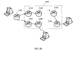
- FIG. 3B shows a schematic diagram of another implementation environment of a method for detecting connectivity according to an embodiment of the present invention.
- the implementation environment includes a source node routing bridge 310B and several non-source node routing bridges 320B, and connectivity detection request information may be sent by the source node routing bridge to one or some of the non-source node routing bridges according to a rule, and may be forwarded between the non-source node routing bridges according to a predetermined rule.
- the source node routing bridge 310B may serve as a start node of a designated path in a designated multicast distribution tree during multicasting of the connectivity detection request information, and the source node routing bridge 310B may send the connectivity detection request information to a routing bridge on another node.
- the non-source node routing bridges 320B may serve as routing bridges that receive and/or forward the connectivity detection request information during the multicasting of the connectivity detection request information.
- the designated path in the multicast distribution tree generally includes a plurality of non-source node routing bridges 320B that is connected in sequence. As shown in FIG. 3B , the designated path may include a non-source node routing bridge 321B, a non-source node routing bridge 322B...a non-source node routing bridge 323B, and a non-source node routing bridge 324B that are connected in sequence, where the first non-source node routing bridge 321B is connected to the source node routing bridge 310B.
- a multicast packet (that is, an OAM packet including the connectivity detection request information) sent by the source node routing bridge 310B is multicast along the designated path, and the source node routing bridge 310B may designate, in the connectivity detection request information of the multicast packet, one or more of the non-source node routing bridge 321b, the non-source node routing bridge 322B...the non-source node routing bridge 323B, and the non-source node routing bridge 324B as one or more target node routing bridges.
- non-source node routing bridges for example, a non-source node routing bridge 325B and a non-source routing bridge 326B, which are in the designated multicast distribution tree but are not on the designated path to a designated target node.
- FIG. 4 is a flowchart of a method for detecting connectivity according to Embodiment 1 of the present invention.
- the method for detecting connectivity may be performed on the non-source node routing bridge 320A in FIG. 3A , for example, the method may be performed by any one of the non-source node routing bridge 321A, the non-source node routing bridge 322A...the non-source node routing bridge 323A, and the non-source node routing bridge 324A.
- the method for detecting connectivity may also be performed on the non-source node routing bridge 320B in FIG.
- the method may be performed by any one of the non-source node routing bridge 321B, the non-source node routing bridge 322B...the non-source node routing bridge 323B, and the non-source node routing bridge 324B.
- the method for detecting connectivity includes:
- the node that receives the connectivity detection request information determines that it is one of designated target nodes according to the nicknames of the target nodes in the received connectivity detection request information, the node sends connectivity detection reply information to a corresponding source node according to the nickname of the source node designated in the connectivity detection request information.
- the node that receives the connectivity detection request information determines that it is not one of the designated target nodes according to the nicknames of the target nodes in the received connectivity detection request information, the node performs corresponding processing according to a value of the hop count in the connectivity detection request information and whether the node is on a path that is in the multicast distribution tree and is from the source node to any one of the target nodes.
- a plurality of designated target nodes in a multicast distribution tree can send connectivity detection reply information to a source node, so that connectivity detection and fault diagnosis can be performed on the plurality of designated target nodes.
- the node that receives the connectivity detection request information may first determine whether it is one of the target nodes, and may also forward the connectivity detection request information according to the hop count. Therefore, two different cases may occur in an application of the method for detecting connectivity, for example, in the following Embodiment 2, after the node that receives the connectivity detection request information first determines whether it is one of the target nodes, the node forwards the connectivity detection request information according to the hop count, while in the following Embodiment 5, the node that receives the connectivity detection request information first forwards the connectivity detection request information through common multicasting according to the hop count, and then determines whether the node itself is one of the target nodes.
- FIG. 5 is a flowchart of a method for detecting connectivity according to Embodiment 2 of the present invention.
- the method for detecting connectivity is performed on the non-source node routing bridge 320A in FIG. 3A , for example, the connectivity detection request information may be processed by any one of the non-source node routing bridge 321A, the non-source node routing bridge 322A...the non-source node routing bridge 323A, and the non-source node routing bridge 324A.
- the method for detecting connectivity includes:
- the connectivity detection request information includes a nickname of a source node, a multicast distribution tree nickname, nicknames of target nodes, and a hop count.
- the connectivity detection request information is sent by the source node routing bridge 310A (that is, the source node), where the nickname of the source node is used to identify which routing bridge is the source node during a multicast process, the multicast distribution tree nickname is used to identify a designated multicast distribution tree, the nicknames of the target nodes are used to identify which routing bridge is a designated target node during the multicast process, and the hop count is used to represent the number of forwardings that can be performed from the source node. There may be one or more target nodes.
- the connectivity detection request information is sent by using an OAM packet carried in an OAM channel of the TRILL protocol.
- the nickname of the source node, the multicast distribution tree nickname, and the hop count that are included in the connectivity detection request information may be defined in a TRILL header, and a format of the TRILL header is shown in FIG. 1 , where the egress routing bridge nickname may be used to store the multicast distribution tree nickname and the ingress routing bridge nickname may be used to store the nickname of the source node.
- the TRILL protocol uses a channel used to carry an OAM packet.
- a format of the channel is shown in FIG. 6 , which includes a link header (Link Header), a transparent interconnection of lots of links header (TRILL Header), an inner Ethernet header (Inner Ethernet Header), a routing bridge channel header (Rbridge Channel Header), a protocol specific payload (Protocol Specific Payload), and a link trailer (Link Trailer).
- the transparent interconnection of lots of links header is the header shown in FIG. 1
- the inner Ethernet header is an original Ethernet header
- the protocol specific payload may be used to store the nicknames of the target nodes.
- a routing bridge decapsulates the OAM packet to obtain the connectivity detection request information, that is, to obtain the nickname of the source node, the multicast distribution tree nickname, and the hop count that are in the transparent interconnection of lots of links header, and the nicknames of the target nodes in the protocol specific payload.
- the OAM packet channel may not use the format show in FIG. 6 completely. So long as an identifier can differentiate the OAM packet of the TRILL from a common data packet, it may be considered that the OAM packet channel is used.
- the non-source node routing bridge 320A After receiving the connectivity detection request information, the non-source node routing bridge 320A sends the connectivity detection request information to a processor of the non-source node routing bridge 320A for processing; the processor compares the nicknames of the target nodes in the connectivity detection request information with a node nickname of the non-source node routing bridge 320A, and determines whether the non-source node routing bridge 320A is one of the target nodes.
- a source node is determined according to the nickname of the source node in the connectivity detection request information, and the connectivity detection reply information is sent to the source node.
- the set threshold here is a preset value, and the threshold is a critical value at which a value of the hop count changes from a valid value to an invalid value; the valid value indicates that the node can forward the received connectivity detection request information, while the invalid value indicates that the node cannot continue to forward the received connectivity connection request information.
- the threshold is generally 1.
- the source node routing bridge when sending the connectivity detection request information for the first time, the source node routing bridge initializes the value of the hop count and the value becomes 1, which indicates that the connectivity detection request information can be forwarded once. In this case, it is determined accordingly that the hop count is the set threshold.
- the hop count is the set threshold, that is, the hop count is 1, after the node that receives the connectivity detection request information deducts the hop count by 1, the hop count becomes 0. Therefore, the connectivity detection request information is not forwarded again.
- the hop count is not the set threshold, that is, the hop count is greater than 1 and the hop count is not 0 after it is deducted by 1, whether the node that receives the connectivity detection request information is on a path from the source node to another target node is further determined.
- the target node here is a target node corresponding to the node that receives the connectivity detection request information when it is determined that the node is on a path from the source node to a target node. There may be one or more target nodes.
- the hop count is not the set threshold, it indicates that the hop count is greater than 1. In this case, the hop count is not 0 after it is deducted by 1, and next forwarding may be performed. Therefore, the hop count is deducted by 1 to generate latest connectivity detection request information including a latest hop count, and the latest connectivity detection request information is forwarded to a next hop node corresponding to the current target node.
- a process of obtaining a next hop node is specifically as follows: querying a pre-stored database to obtain a next hop node according to path information in the database, where the database stores information about a path that is in the multicast distribution tree and is from the source node to each target node.
- the path information here is obtained by calculation after the multicast distribution tree, the source node, and the target node are determined, and is stored in a database of each node on the path, where the database is called a link state database (Link State DataBase, LSDB for short).
- Link State DataBase LSDB for short.
- hop count is the set threshold, it indicates that when the node is not a target node, the hop count is 1, and the hop count is 0 after it is deducted by 1, so that next forwarding cannot be performed.
- a source node is determined according to the nickname of the source node, and unreachable information is sent to the source node.
- connectivity detection request information of a plurality of designated target nodes can be sent on a source node, so that all the designated target nodes in a multicast distribution tree can send connectivity detection reply information to the source node, while all non-target nodes that are in the multicast distribution tree and on a designated path from the source node to a target node send unreachable information to the source node.
- connectivity detection and fault diagnosis can be performed on the plurality of designated target nodes, and the source node is capable of receiving only information sent by a node on a true path, thereby making it easier to identify a path.
- connectivity detection is performed on a node on a specific network according to the method for detecting connectivity described in Embodiment 2. For details, reference may be made to Embodiment 3.
- FIG. 7 is a schematic diagram of testing a multicast path by using traceroute according to Embodiment 3 of the present invention.
- FIG. 7 shows a routing bridge RB1 to a routing bridge RB7, where a tree formed by bold lines connecting the routing bridges is a multicast distribution tree tree2, and a routing bridge RB2 is a root of the multicast distribution tree.
- the routing bridge RB1 as a source node (corresponding to the source node routing bridge 310A in FIG. 3A ) and using a routing bridge RB5 and a routing bridge RB4 as target nodes (corresponding to the non-source node routing bridge 324A in FIG. 3A )
- connectivity detection is performed on the source node RB1 to the target nodes RB4 and RB5.
- a specific process is as follows:
- the method for detecting connectivity is based on an assumption that after receiving related connectivity detection request information, each routing bridge sends the connectivity detection request information to a processor for processing, and further determines, according to a processing result, whether to continue to forward the connectivity detection request information and to which routing bridge the connectivity detection request information is forwarded according to an LSDB.
- connectivity detection request information of a plurality of designated target nodes can be sent on a source node, so that all the designated target nodes in a multicast distribution tree can send connectivity detection reply information to the source node, while all non-target nodes that are in the multicast distribution tree and on a designated path from the source node to a target node send unreachable information to the source node.
- connectivity detection and fault diagnosis can be performed on the plurality of designated target nodes, and the source node is capable of receiving only information sent by a node on a true path, thereby making it easier to identify a path.
- the present invention may further provide a corresponding method for sending connectivity detection request information.
- the connectivity detection request information received and processed in Embodiment 2 may further provide a corresponding method for sending connectivity detection request information.
- Embodiment 4 For details, reference may be made to Embodiment 4.
- FIG. 8 is a flowchart of a method for sending connectivity detection request information according to Embodiment 4 of the present invention.
- the method for sending connectivity detection request information is implemented on the source node routing bridge 310A in FIG. 3A .
- the method for sending connectivity detection request information includes:
- the database stores information about a path that is in a multicast distribution tree and is from a source node to a target node.
- information about a path that is in the multicast distribution tree and is from the source node to each target node may be learnt by calculation.
- the path information is generally stored in a database of each routing bridge, and when a routing bridge needs to perform forwarding, the routing bridge may learn a next hop routing bridge node according to the path information in the database.
- the connectivity detection request information includes a nickname of the source node, a multicast distribution tree nickname, a nickname of the target node, and a hop count.
- the nickname of the source node is used to identify which routing bridge is a source node during a multicast process
- the multicast distribution tree nickname is used to identify a designated multicast distribution tree
- the nickname of the target node is used to identify which routing bridge or which routing bridges are the designated target node during the multicast process
- the hop count is used to represent the number of forwardings that can be performed from the source node.
- the nickname of the source node, the multicast distribution tree nickname, and the hop count that are in the connectivity detection request information may be defined in a TRILL header, and a format of the TRILL header is shown in FIG. 1 , where the egress routing bridge nickname may be used to store the multicast distribution tree nickname and the ingress routing bridge nickname may be used to store the nickname of the source node.
- the TRILL protocol uses a channel used to carry an OAM packet.
- a format of the channel is shown in FIG. 6 , which includes a link header (Link Header), a transparent interconnection of lots of links header (TRILL Header), an inner Ethernet header (Inner Ethernet Header), a routing bridge channel header (Rbridge Channel Header), a protocol specific payload (Protocol Specific Payload), and a link trailer (Link Trailer).
- the transparent interconnection of lots of links header is the header shown in FIG. 1
- the inner Ethernet header is an original Ethernet header
- the protocol specific payload may be used to store the nickname of the target node.
- a routing bridge decapsulates the OAM packet to obtain the nickname of the source node, the multicast distribution tree nickname, and the hop count in the transparent interconnection of lots of links header, and the nickname of the target node in the protocol specific load.
- the nickname of the target node may also be stored in the OAM packet in another manner.
- step 810 and step 820 need to be performed.
- the source node routing bridge 310A may also receive unreachable information sent by the non-source node routing bridge 320A. In this case, the source node routing bridge 310A first adds 1 to the hop count in the connectivity detection request information, and then step 810 and step 820 are performed.
- the non-source node routing bridge 320A determines that the non-source node routing bridge 320A is not a target node and is not on a path that is in the multicast distribution tree and is from the source node to a target node, the non-source node routing bridge 320A sends unreachable information to the source node routing bridge 310A (that is, the source node).
- the unreachable information includes a nickname of a node that sends the unreachable information, so that the source node easily identifies the node that sends the unreachable information and a path formed by all nodes that send unreachable information.
- a multicast distribution tree may be designated, and a plurality of target nodes may also be designated, so that connectivity check and fault diagnosis can be performed directly on the plurality of designated target nodes, thereby featuring high pertinence and high efficiency.
- FIG. 9 is a flowchart of a method for detecting connectivity according to Embodiment 5 of the present invention.
- the method for detecting connectivity is performed on the non-source node routing bridge 320B in FIG. 3B , for example, connectivity detection request information may be processed through multicasting by any one of the non-source node routing bridge 321B, the non-source node routing bridge 322B...the non-source node routing bridge 323B, or the non-source node routing bridge 325B and the non-source node routing bridge 326B.
- the method for detecting connectivity includes:
- the connectivity detection request information includes a nickname of a source node, a multicast distribution tree nickname, nicknames of target nodes, and a hop count.
- the connectivity detection request information is sent by the source node routing bridge 310B (that is, the source node), where the nickname of the source node is used to identify which routing bridge is a source node during a multicast process, the multicast distribution tree nickname is used to identify a designated multicast distribution tree, the nicknames of the target nodes are used to identify which routing bridge is the designated target node (there may be one or more target nodes) during the multicast process, and the hop count is used to represent the number of forwardings that can be performed from the source node.
- the source node routing bridge 310B that is, the source node
- the nickname of the source node is used to identify which routing bridge is a source node during a multicast process
- the multicast distribution tree nickname is used to identify a designated multicast distribution tree
- the nicknames of the target nodes are used to identify which routing bridge is the designated target node (there may be one or more target nodes) during the multicast process
- the hop count is used to represent the number of forwardings that
- the nickname of the source node, the multicast distribution tree nickname, and the hop count that are included in the connectivity detection request information may be defined in a TRILL header, and a format of the TRILL header is shown in FIG. 1 , where the egress routing bridge nickname may be used to store the multicast distribution tree nickname and the ingress routing bridge nickname may be used to store the nickname of the source node.
- the TRILL protocol uses a channel used to carry an OAM packet.
- a format of the channel is shown in FIG. 6 , which includes a link header (Link Header), a transparent interconnection of lots of links header (TRILL Header), an inner Ethernet header (Inner Ethernet Header), a routing bridge channel header (Rbridge Channel Header), a protocol specific payload (Protocol Specific Payload), and a link trailer (Link Trailer).
- the transparent interconnection of lots of links header is the header shown in FIG. 1
- the inner Ethernet header is an original Ethernet header
- the protocol specific payload may be used to store the nicknames of the target nodes.
- a routing bridge when receiving the OAM packet, decapsulates the OAM packet to obtain the nickname of the source node, the multicast distribution tree nickname, and the hop count in the transparent interconnection of lots of links header, and the nicknames of the target nodes in the protocol specific load.
- the non-source node routing bridge 320B after receiving the connectivity detection request information, the non-source node routing bridge 320B first determines whether the hop count in the connectivity detection request information is a set threshold, where the set threshold may be generally set to 1.
- a nickname of the non-source node routing bridge 320B (a local node that is processing multicast data) is compared with the nicknames of the designated target nodes in the connectivity detection request information, and whether the local node is one of the target nodes is determined.
- the hop count is the set threshold, that is, the hop count is 1.
- the local node is not a target node but is on the designated path, which indicates that a multicast path from the source node to a designated target node passes the local node and the local node needs to send unreachable information to the source node.
- the hop count is the set threshold, that is, the hop count is 1.
- the local node is neither a target node nor is on the designated path, which indicates that the multicast path from the source node to the designated target node does not pass the local node and the local node does not need to send any information to the source node.
- the set threshold is generally a critical value at which a value of the hop count changes from a valid value to an invalid value; the valid value indicates that the node can forward the received connectivity detection request information, while the invalid value indicates that the node cannot continue to forward the received connectivity connection request information.
- the hop count in the connectivity detection request information is not the set threshold, it indicates that the value of the hop count is greater than the set threshold, for example, when the set threshold is set to 1, the value of the hop count is greater than 1. If the value of the hop count is greater than 1, it indicates that the connectivity detection request information can be further forwarded at least once.
- a database for example, a link state database LSDB
- LSDB link state database
- the database is a series of paths calculated according to the source node, the multicast distribution tree, and the target nodes, and each path is a path that is in the multicast distribution tree and is from the source node to a target node.
- the nickname of the non-source node routing bridge 320B (the local node that is processing multicast data) is compared with the nicknames of the designated target nodes in the connectivity detection request information, and whether the local node is one of the target nodes is determined.
- the hop count is the set threshold, that is, the hop count is not 1 and is greater than 1.
- the local node is a target node, and needs to send connectivity detection reply information to the source node.
- a non-target node routing bridge when the hop count in the connectivity detection request information is not equal to the set threshold, a non-target node routing bridge only needs to deduct the hop count by 1 and continue to forward the connectivity detection request information. However, a target node routing bridge not only needs to continue to forward the connectivity detection request information after deducting the hop count by 1, but also needs to send connectivity detection reply information to the source node.
- connectivity detection request information of a plurality of designated target nodes can be sent on a source node, so that all the designated target nodes in a multicast distribution tree can send connectivity detection reply information to the source node, while all non-target nodes that are in the multicast distribution tree and on a designated path from the source node to a target node send unreachable information to the source node.
- connectivity detection and fault diagnosis can be performed on the plurality of designated target nodes, and the source node is capable of receiving only information sent by a node on a true path, thereby making it easier to identify a path.
- connectivity detection is performed on a node on a specific network according to the method for detecting connectivity described in Embodiment 5. For details, reference may be made to Embodiment 6.
- FIG. 10 is a schematic diagram of testing a multicast path by using traceroute according to Embodiment 6 of the present invention.
- FIG. 10 shows a routing bridge RB1 to a routing bridge RB8, where a tree formed by black lines connecting routing bridges is a multicast distribution tree tree3, and a routing bridge RB2 is a root (root) of the multicast distribution tree.
- the routing bridge RB1 as a source node (corresponding to the source node routing bridge 310B in FIG. 3B ) and using the routing bridge RB2 and a routing bridge RB4 as target nodes (corresponding to the non-source node routing bridge 324B in FIG. 3B )
- connectivity detection is performed on the source node RB1 to the target nodes RB4 and RB2.
- a specific process is as follows:
- the source node routing bridge RB1 receives unreachable information from the routing bridges RB5 and RB6 in sequence, and finally receives connectivity detection reply information from the target node routing bridges RB2 and RB4.
- each node that receives the connectivity detection request information first forwards the information through common multicasting, and then determines whether the node itself is a target node and whether to send related information to the source node.
- the source node also performs forwarding through common multicasting.
- connectivity detection request information of a plurality of designated target nodes can be sent on a source node, so that all the designated target nodes in a multicast distribution tree can send connectivity detection reply information to the source node, while all non-target nodes that are in the multicast distribution tree and on a path from the source node to a target node send unreachable information to the source node.
- connectivity detection and fault diagnosis can be performed on the designated target nodes, and the source node is capable of receiving only information sent by a node on a true path, thereby making it easier to identify a path.
- the present invention may further provide a corresponding method for sending connectivity detection request information.
- the connectivity detection request information received and processed in Embodiment 5 may further provide a corresponding method for sending connectivity detection request information.
- Embodiment 7 For details, reference may be made to Embodiment 7.
- FIG. 11 is a flowchart of a method for sending connectivity detection request information according to Embodiment 7 of the present invention.
- the method for sending connectivity detection request information is implemented on the source node routing bridge 310B in FIG. 3B .
- the method for sending connectivity detection request information includes:
- the non-source node routing bridge 320B determines that it is not a target node and is on a path that is in a multicast distribution tree and is from a source node to a target node, the non-source node routing bridge 320B sends the unreachable information to the source node routing bridge 310B (that is, the source node).
- the unreachable information includes a nickname of a node that sends the unreachable information.
- the source node easily identifies the node that sends the unreachable information and a path formed by all nodes that send unreachable information.
- the source node When forwarding the connectivity detection request information, the source node here may forward the connectivity detection request information through common multicasting, that is, it may forward the connectivity detection request information to all routing bridges that is in the multicast distribution tree and connected to the source node directly.
- the connectivity detection request information here is generally included in the connectivity detection request information, and generally includes a nickname of the source node, a nickname of the designated multicast distribution tree, nicknames of target nodes, and a hop count.
- the source node routing bridge 310B when forwarding the connectivity detection request information for the first time, the source node routing bridge 310B sends the connectivity detection request information directly through multicasting, that is, only step 112 is performed. During a subsequent multicast process, the source node routing bridge 310B receives unreachable information returned by the non-source node routing bridge 320B continuously. Step 111 and step 112 are performed only in this case.
- a multicast distribution tree may be designated, and a plurality of target nodes may also be designated, so that connectivity check and fault diagnosis can be performed directly on the plurality of designated target nodes, thereby featuring high efficiency.
- FIG. 12 is a schematic structural diagram of an apparatus for detecting connectivity according to Embodiment 8 of the present invention.
- the apparatus for detecting connectivity apparatus includes a receiver 121, a determining module 122, a transmitter 123, and a processing module 124.
- the receiver 121 may be configured to receive connectivity detection request information, where the connectivity detection request information includes a nickname of a source node, a nickname of a multicast distribution tree, nicknames of target nodes, and a hop count.
- the determining module 122 may be configured to determine, according to the nicknames of the target nodes, whether a node that receives the connectivity detection request information is one of the target nodes.
- the transmitter 123 may be configured to: when the determining module determines that the node is one of the target nodes, send connectivity detection reply information to the source node according to the nickname of the source node.
- the processing module 124 may be configured to: when the determining module 122 determines that the node is not one of the target nodes, perform corresponding processing according to a value of the hop count and whether the node is on a path that is in the multicast distribution tree and is from the source node to any one of the target nodes.
- a multicast distribution tree may be designated, and a plurality of target nodes may also be designated, so that connectivity check and fault diagnosis can be performed directly on the plurality of designated target nodes, thereby featuring high efficiency.
- the apparatus for detecting connectivity may also include a more specific structure.
- the apparatus for detecting connectivity may also include a more specific structure.
- FIG. 13 is a schematic structural diagram of an apparatus for detecting connectivity according to Embodiment 9 of the present invention.
- the apparatus for detecting connectivity includes the receiver 121, the determining module 122, the returning module 123, and the processing module 124 shown in Embodiment 8, and further includes a first forwarding module 125.
- the receiver 121, the determining module 122, and the returning module 123 plays a role same as that shown in FIG. 12 , which is not described herein again.
- the first forwarding module 125 may be configured to determine whether the hop count is a set threshold; if the hop count is not the set threshold, determine whether the node is on a path that is in the multicast distribution tree and is from the source node and any one of the target nodes; if the node is on a path that is in the multicast distribution tree and is from the source node to any one of the target nodes, deduct the hop count by 1, and forward the connectivity detection request information including an updated hop count to a next hop node corresponding to a target node; and if the hop count is the set threshold, stop forwarding the connectivity detection request information.
- the processing module 124 here may be specifically configured to: when the determining module determines that the node is not one of the target nodes, determine whether the hop count is the set threshold; if the hop count is the set threshold, send unreachable information to the source node according to the nickname of the source node, and stop forwarding the connectivity detection request information; if the hop count is not the set threshold, deduct the hop count by 1, and forward the connectivity detection request information including an updated hop count to a next hop corresponding to a target node.
- a multicast distribution tree may be designated, and a plurality of target nodes may also be designated, so that connectivity check and fault diagnosis can be performed directly on the plurality of designated target nodes, thereby featuring high efficiency.
- FIG. 14 is a schematic structural diagram of an apparatus for detecting connectivity according to Embodiment 9 of the present invention.
- the apparatus for detecting connectivity includes the receiver 121, the determining module 122, the transmitter 123, and the processing module 124 shown in Embodiment 8, and further includes a second forwarding module 126.
- the receiver 121, the determining module 122, and the transmitter 123 plays a role same as that shown in FIG. 12 , which is not described herein again.
- the second forwarding module 126 may be configured to determine whether the hop count is a set threshold; if the hop count is not the set threshold, deduct the hop count by 1, and forward the connection detection request information including an updated hop count through multicasting along the multicast distribution tree.
- the processing module 124 here may be configured to: if the determining module 122 determines that the node is not one of the target nodes, when the hop count is the set threshold, determine whether the node is on a path that is in the multicast distribution tree and is from the source node to the target node; if the node is on a path that is in the multicast distribution tree and is from the source node to any one of the target nodes, send unreachable information to the source node according to the nickname of the source node; if the node is not on any path that is in the multicast distribution tree and is from the source node to any one of the target nodes, send no information; and when the hop count is not the set threshold, send no information.
- the apparatus for detecting connectivity provided by the foregoing embodiment is specifically described, division of the foregoing functional modules is used as an example only. In an actual application, the foregoing function allocation can be completed by different functional modules as required, that is, an internal structure of the apparatus is divided into different functional modules to perform all or some of the foregoing functions.
- the apparatus for detecting connectivity provided by the foregoing embodiment and Embodiment 5 of the method for detecting connectivity belong to a same idea. For a specific implementation process of the apparatus for detecting connectivity, reference may be made to the method embodiments, which are not described herein again.
- a multicast distribution tree may be designated, and a plurality of target nodes may also be designated, so that connectivity check and fault diagnosis can be performed directly on the plurality of designated target nodes, thereby featuring high efficiency.
- the program may be stored in a computer readable storage medium.
- the storage medium may include: a read-only memory, a magnetic disk, or an optical disc.
Landscapes
- Engineering & Computer Science (AREA)
- Computer Networks & Wireless Communication (AREA)
- Signal Processing (AREA)
- Environmental & Geological Engineering (AREA)
- Data Exchanges In Wide-Area Networks (AREA)
Applications Claiming Priority (2)
| Application Number | Priority Date | Filing Date | Title |
|---|---|---|---|
| CN201210165624XA CN103428045A (zh) | 2012-05-25 | 2012-05-25 | 连通性检测方法、装置和系统 |
| PCT/CN2012/083910 WO2013174101A1 (zh) | 2012-05-25 | 2012-11-01 | 连通性检测方法、装置和系统 |
Publications (2)
| Publication Number | Publication Date |
|---|---|
| EP2838227A1 true EP2838227A1 (de) | 2015-02-18 |
| EP2838227A4 EP2838227A4 (de) | 2015-06-03 |
Family
ID=49623055
Family Applications (1)
| Application Number | Title | Priority Date | Filing Date |
|---|---|---|---|
| EP12877586.3A Withdrawn EP2838227A4 (de) | 2012-05-25 | 2012-11-01 | Verfahren, vorrichtung und system zur konnektivitätserkennung |
Country Status (4)
| Country | Link |
|---|---|
| US (1) | US9491074B2 (de) |
| EP (1) | EP2838227A4 (de) |
| CN (1) | CN103428045A (de) |
| WO (1) | WO2013174101A1 (de) |
Cited By (1)
| Publication number | Priority date | Publication date | Assignee | Title |
|---|---|---|---|---|
| EP3242441A4 (de) * | 2014-12-30 | 2017-12-27 | Huawei Technologies Co. Ltd. | Bit-weiterleitender eingangsrouter, bit-weiterleitender router und betriebs-, verwaltungs- und wartungsdetektionsverfahren |
Families Citing this family (12)
| Publication number | Priority date | Publication date | Assignee | Title |
|---|---|---|---|---|
| CN103795624A (zh) * | 2014-02-14 | 2014-05-14 | 浪潮通信信息系统有限公司 | 一种传输电路路由串通的方法 |
| EP3145122B1 (de) * | 2014-06-30 | 2018-09-19 | Huawei Technologies Co. Ltd. | Pfaderkennungsverfahren und pfadberechnungselement |
| US20160099859A1 (en) * | 2014-10-06 | 2016-04-07 | Futurewei Technologies, Inc. | Reverse Path Validation for Source Routed Networks |
| CN105634776B (zh) * | 2014-10-31 | 2020-01-31 | 华为技术有限公司 | 一种确定报文转发接口的方法及设备 |
| KR102419647B1 (ko) * | 2015-09-10 | 2022-07-11 | 삼성전자주식회사 | 패킷을 전송하는 장치 및 방법 |
| CN107147508B (zh) * | 2016-03-01 | 2022-11-01 | 中兴通讯股份有限公司 | 故障检测方法及装置 |
| CN107566280A (zh) | 2016-06-30 | 2018-01-09 | 上海诺基亚贝尔股份有限公司 | 验证组播数据路径的方法和路由器设备 |
| CN108111327B (zh) * | 2016-11-25 | 2021-10-26 | 上海诺基亚贝尔股份有限公司 | 网络操作管理维护方法和装置 |
| JP6915454B2 (ja) * | 2017-08-24 | 2021-08-04 | 富士通株式会社 | 通信プログラム、通信方法及び通信装置 |
| CN110581880B (zh) * | 2019-05-29 | 2021-09-07 | 阿里巴巴集团控股有限公司 | 通信链路的建立方法及装置,节点标识确定方法及装置 |
| CN113973066A (zh) * | 2020-07-24 | 2022-01-25 | 华为技术有限公司 | 对p2mp树连通性检测的方法、设备和系统 |
| CN115454015B (zh) * | 2022-07-28 | 2024-09-13 | 重庆长安汽车股份有限公司 | 控制器节点检测方法、装置、控制系统、车辆及存储介质 |
Family Cites Families (9)
| Publication number | Priority date | Publication date | Assignee | Title |
|---|---|---|---|---|
| CN101179479A (zh) | 2006-11-09 | 2008-05-14 | 华为技术有限公司 | 一种以太网的操作管理和维护报文的传输方法、系统和节点 |
| CN101369922B (zh) * | 2008-09-28 | 2011-04-06 | 华为技术有限公司 | 一种连通性检测方法和维护域终点及系统 |
| CN101420385A (zh) * | 2008-12-12 | 2009-04-29 | 北京邮电大学 | 一种实现t-mpls与对等的mpls网络oam功能互通的机制 |
| US8634308B2 (en) * | 2010-06-02 | 2014-01-21 | Brocade Communications Systems, Inc. | Path detection in trill networks |
| US8588081B2 (en) * | 2010-07-14 | 2013-11-19 | Cisco Technology, Inc. | Monitoring a flow set to detect faults |
| US8345697B2 (en) * | 2010-08-17 | 2013-01-01 | Dell Products, Lp | System and method for carrying path information |
| US8634297B2 (en) * | 2010-11-01 | 2014-01-21 | Cisco Technology, Inc. | Probing specific customer flow in layer-2 multipath networks |
| US20120163164A1 (en) * | 2010-12-27 | 2012-06-28 | Brocade Communications Systems, Inc. | Method and system for remote load balancing in high-availability networks |
| CN102118773B (zh) * | 2011-03-21 | 2014-08-20 | 华为技术有限公司 | 检测网络节点间链路连接状态的方法及相关设备 |
-
2012
- 2012-05-25 CN CN201210165624XA patent/CN103428045A/zh not_active Withdrawn
- 2012-11-01 EP EP12877586.3A patent/EP2838227A4/de not_active Withdrawn
- 2012-11-01 WO PCT/CN2012/083910 patent/WO2013174101A1/zh not_active Ceased
-
2014
- 2014-11-06 US US14/534,461 patent/US9491074B2/en not_active Expired - Fee Related
Cited By (6)
| Publication number | Priority date | Publication date | Assignee | Title |
|---|---|---|---|---|
| EP3242441A4 (de) * | 2014-12-30 | 2017-12-27 | Huawei Technologies Co. Ltd. | Bit-weiterleitender eingangsrouter, bit-weiterleitender router und betriebs-, verwaltungs- und wartungsdetektionsverfahren |
| US10313216B2 (en) | 2014-12-30 | 2019-06-04 | Huawei Technologies Co., Ltd. | Bit-forwarding ingress router, bit-forwarding router, and operation, administration and maintenance test method |
| US10965568B2 (en) | 2014-12-30 | 2021-03-30 | Huawei Technologies Co., Ltd. | Bit-forwarding ingress router, bit-forwarding router, and operation, administration and maintenance test method |
| EP4089981A1 (de) * | 2014-12-30 | 2022-11-16 | Huawei Technologies Co., Ltd. | Bit-weiterleitender eingangsrouter, bit-weiterleitender router und betriebs-, verwaltungs- und wartungsdetektionsverfahren |
| US11558274B2 (en) | 2014-12-30 | 2023-01-17 | Huawei Technologies Co., Ltd. | Bit-forwarding ingress router, bit-forwarding router, and operation, administration and maintenance test method |
| US11894998B2 (en) | 2014-12-30 | 2024-02-06 | Huawei Technologies Co., Ltd. | Bit-forwarding ingress router, bit-forwarding router, and operation, administration and maintenance test method |
Also Published As
| Publication number | Publication date |
|---|---|
| EP2838227A4 (de) | 2015-06-03 |
| US9491074B2 (en) | 2016-11-08 |
| US20150063094A1 (en) | 2015-03-05 |
| WO2013174101A1 (zh) | 2013-11-28 |
| CN103428045A (zh) | 2013-12-04 |
Similar Documents
| Publication | Publication Date | Title |
|---|---|---|
| EP2838227A1 (de) | Verfahren, vorrichtung und system zur konnektivitätserkennung | |
| US9917745B2 (en) | Validation of chained network services | |
| US9698994B2 (en) | Loop detection and repair in a multicast tree | |
| CN108123824B (zh) | 一种网络故障检测方法及装置 | |
| CN103036787B (zh) | 一种网络路由收敛处理方法和装置 | |
| JP7430224B2 (ja) | パケット処理方法およびゲートウェイ・デバイス | |
| US10355937B2 (en) | Systems and methods for determining a topology of a network comprising a plurality of intermediary devices and paths | |
| US11139995B2 (en) | Methods and router devices for verifying a multicast datapath | |
| CN112787843B (zh) | 故障节点的检测方法和存储介质及电子装置 | |
| US20070041328A1 (en) | Devices and methods of using link status to determine node availability | |
| CN104954153A (zh) | 节点故障检测方法及装置 | |
| CN105743687B (zh) | 节点故障的判断方法及装置 | |
| CN115473840A (zh) | 一种报文发布方法、转发路径处理方法及装置 | |
| CN105634776B (zh) | 一种确定报文转发接口的方法及设备 | |
| CN102437960B (zh) | 集群模式的检测处理方法、系统和网络设备 | |
| Malekzadeh et al. | Network topology inference from end-to-end unicast measurements | |
| CN101771604A (zh) | 路由探测方法、系统以及中间路由装置 | |
| WO2019007139A1 (zh) | 一种实现故障检测的方法、设备和系统 | |
| US9893979B2 (en) | Network topology discovery by resolving loops | |
| US10476774B2 (en) | Selective transmission of bidirectional forwarding detection (BFD) messages for verifying multicast connectivity | |
| US9667439B2 (en) | Determining connections between disconnected partial trees | |
| US10250477B2 (en) | Method and controller for announcing bandwidth of cluster system | |
| CN102571464B (zh) | 链路的跟踪处理方法及系统 | |
| US8614958B2 (en) | Systems and methods of snooping connectivity fault messages to configure maintenance end point for alarm suppression messages | |
| CN102857415B (zh) | 介质访问控制地址学习控制方法、装置和路由桥 |
Legal Events
| Date | Code | Title | Description |
|---|---|---|---|
| PUAI | Public reference made under article 153(3) epc to a published international application that has entered the european phase |
Free format text: ORIGINAL CODE: 0009012 |
|
| 17P | Request for examination filed |
Effective date: 20141111 |
|
| AK | Designated contracting states |
Kind code of ref document: A1 Designated state(s): AL AT BE BG CH CY CZ DE DK EE ES FI FR GB GR HR HU IE IS IT LI LT LU LV MC MK MT NL NO PL PT RO RS SE SI SK SM TR |
|
| AX | Request for extension of the european patent |
Extension state: BA ME |
|
| RA4 | Supplementary search report drawn up and despatched (corrected) |
Effective date: 20150506 |
|
| RIC1 | Information provided on ipc code assigned before grant |
Ipc: H04L 12/26 20060101ALI20150428BHEP Ipc: H04L 12/24 20060101AFI20150428BHEP |
|
| DAX | Request for extension of the european patent (deleted) | ||
| STAA | Information on the status of an ep patent application or granted ep patent |
Free format text: STATUS: THE APPLICATION IS DEEMED TO BE WITHDRAWN |
|
| 18D | Application deemed to be withdrawn |
Effective date: 20151202 |