EP2838434B1 - Dispositif de microbiopsie - Google Patents
Dispositif de microbiopsie Download PDFInfo
- Publication number
- EP2838434B1 EP2838434B1 EP13778287.6A EP13778287A EP2838434B1 EP 2838434 B1 EP2838434 B1 EP 2838434B1 EP 13778287 A EP13778287 A EP 13778287A EP 2838434 B1 EP2838434 B1 EP 2838434B1
- Authority
- EP
- European Patent Office
- Prior art keywords
- chamber
- microbiopsy
- cutting elements
- plates
- cutting
- Prior art date
- Legal status (The legal status is an assumption and is not a legal conclusion. Google has not performed a legal analysis and makes no representation as to the accuracy of the status listed.)
- Active
Links
Images



Classifications
-
- A—HUMAN NECESSITIES
- A61—MEDICAL OR VETERINARY SCIENCE; HYGIENE
- A61B—DIAGNOSIS; SURGERY; IDENTIFICATION
- A61B10/00—Instruments for taking body samples for diagnostic purposes; Other methods or instruments for diagnosis, e.g. for vaccination diagnosis, sex determination or ovulation-period determination; Throat striking implements
- A61B10/0096—Casings for storing test samples
-
- A—HUMAN NECESSITIES
- A61—MEDICAL OR VETERINARY SCIENCE; HYGIENE
- A61B—DIAGNOSIS; SURGERY; IDENTIFICATION
- A61B10/00—Instruments for taking body samples for diagnostic purposes; Other methods or instruments for diagnosis, e.g. for vaccination diagnosis, sex determination or ovulation-period determination; Throat striking implements
- A61B10/02—Instruments for taking cell samples or for biopsy
- A61B10/0233—Pointed or sharp biopsy instruments
-
- A—HUMAN NECESSITIES
- A61—MEDICAL OR VETERINARY SCIENCE; HYGIENE
- A61B—DIAGNOSIS; SURGERY; IDENTIFICATION
- A61B10/00—Instruments for taking body samples for diagnostic purposes; Other methods or instruments for diagnosis, e.g. for vaccination diagnosis, sex determination or ovulation-period determination; Throat striking implements
- A61B10/02—Instruments for taking cell samples or for biopsy
- A61B10/0233—Pointed or sharp biopsy instruments
- A61B10/0266—Pointed or sharp biopsy instruments means for severing sample
-
- A—HUMAN NECESSITIES
- A61—MEDICAL OR VETERINARY SCIENCE; HYGIENE
- A61B—DIAGNOSIS; SURGERY; IDENTIFICATION
- A61B5/00—Measuring for diagnostic purposes; Identification of persons
- A61B5/15—Devices for taking samples of blood
- A61B5/150007—Details
- A61B5/150206—Construction or design features not otherwise provided for; manufacturing or production; packages; sterilisation of piercing element, piercing device or sampling device
- A61B5/150274—Manufacture or production processes or steps for blood sampling devices
- A61B5/150282—Manufacture or production processes or steps for blood sampling devices for piercing elements, e.g. blade, lancet, canula, needle
-
- A—HUMAN NECESSITIES
- A61—MEDICAL OR VETERINARY SCIENCE; HYGIENE
- A61B—DIAGNOSIS; SURGERY; IDENTIFICATION
- A61B5/00—Measuring for diagnostic purposes; Identification of persons
- A61B5/15—Devices for taking samples of blood
- A61B5/150007—Details
- A61B5/150374—Details of piercing elements or protective means for preventing accidental injuries by such piercing elements
- A61B5/150381—Design of piercing elements
- A61B5/150442—Blade-like piercing elements, e.g. blades, cutters, knives, for cutting the skin
- A61B5/15045—Blade-like piercing elements, e.g. blades, cutters, knives, for cutting the skin comprising means for capillary action
-
- A—HUMAN NECESSITIES
- A61—MEDICAL OR VETERINARY SCIENCE; HYGIENE
- A61B—DIAGNOSIS; SURGERY; IDENTIFICATION
- A61B17/00—Surgical instruments, devices or methods
- A61B17/32—Surgical cutting instruments
- A61B17/3205—Excision instruments
- A61B17/32053—Punch like cutting instruments, e.g. using a cylindrical or oval knife
-
- A—HUMAN NECESSITIES
- A61—MEDICAL OR VETERINARY SCIENCE; HYGIENE
- A61B—DIAGNOSIS; SURGERY; IDENTIFICATION
- A61B17/00—Surgical instruments, devices or methods
- A61B17/32—Surgical cutting instruments
- A61B17/3209—Incision instruments
- A61B17/32093—Incision instruments for skin incisions
-
- A—HUMAN NECESSITIES
- A61—MEDICAL OR VETERINARY SCIENCE; HYGIENE
- A61B—DIAGNOSIS; SURGERY; IDENTIFICATION
- A61B17/00—Surgical instruments, devices or methods
- A61B17/32—Surgical cutting instruments
- A61B17/3209—Incision instruments
- A61B17/3211—Surgical scalpels, knives; Accessories therefor
-
- A—HUMAN NECESSITIES
- A61—MEDICAL OR VETERINARY SCIENCE; HYGIENE
- A61B—DIAGNOSIS; SURGERY; IDENTIFICATION
- A61B17/00—Surgical instruments, devices or methods
- A61B17/32—Surgical cutting instruments
- A61B17/322—Skin grafting apparatus
-
- A—HUMAN NECESSITIES
- A61—MEDICAL OR VETERINARY SCIENCE; HYGIENE
- A61B—DIAGNOSIS; SURGERY; IDENTIFICATION
- A61B17/00—Surgical instruments, devices or methods
- A61B17/00234—Surgical instruments, devices or methods for minimally invasive surgery
- A61B2017/00345—Micromachines, nanomachines, microsystems
-
- A—HUMAN NECESSITIES
- A61—MEDICAL OR VETERINARY SCIENCE; HYGIENE
- A61B—DIAGNOSIS; SURGERY; IDENTIFICATION
- A61B17/00—Surgical instruments, devices or methods
- A61B17/32—Surgical cutting instruments
- A61B2017/320064—Surgical cutting instruments with tissue or sample retaining means
-
- A—HUMAN NECESSITIES
- A61—MEDICAL OR VETERINARY SCIENCE; HYGIENE
- A61B—DIAGNOSIS; SURGERY; IDENTIFICATION
- A61B5/00—Measuring for diagnostic purposes; Identification of persons
- A61B5/15—Devices for taking samples of blood
- A61B5/150007—Details
- A61B5/150374—Details of piercing elements or protective means for preventing accidental injuries by such piercing elements
- A61B5/150381—Design of piercing elements
- A61B5/150442—Blade-like piercing elements, e.g. blades, cutters, knives, for cutting the skin
-
- A—HUMAN NECESSITIES
- A61—MEDICAL OR VETERINARY SCIENCE; HYGIENE
- A61B—DIAGNOSIS; SURGERY; IDENTIFICATION
- A61B5/00—Measuring for diagnostic purposes; Identification of persons
- A61B5/15—Devices for taking samples of blood
- A61B5/150007—Details
- A61B5/150374—Details of piercing elements or protective means for preventing accidental injuries by such piercing elements
- A61B5/150381—Design of piercing elements
- A61B5/150442—Blade-like piercing elements, e.g. blades, cutters, knives, for cutting the skin
- A61B5/150458—Specific blade design, e.g. for improved cutting and penetration characteristics
-
- A—HUMAN NECESSITIES
- A61—MEDICAL OR VETERINARY SCIENCE; HYGIENE
- A61M—DEVICES FOR INTRODUCING MEDIA INTO, OR ONTO, THE BODY; DEVICES FOR TRANSDUCING BODY MEDIA OR FOR TAKING MEDIA FROM THE BODY; DEVICES FOR PRODUCING OR ENDING SLEEP OR STUPOR
- A61M37/00—Other apparatus for introducing media into the body; Percutany, i.e. introducing medicines into the body by diffusion through the skin
- A61M37/0015—Other apparatus for introducing media into the body; Percutany, i.e. introducing medicines into the body by diffusion through the skin by using microneedles
- A61M2037/0053—Methods for producing microneedles
-
- A—HUMAN NECESSITIES
- A61—MEDICAL OR VETERINARY SCIENCE; HYGIENE
- A61M—DEVICES FOR INTRODUCING MEDIA INTO, OR ONTO, THE BODY; DEVICES FOR TRANSDUCING BODY MEDIA OR FOR TAKING MEDIA FROM THE BODY; DEVICES FOR PRODUCING OR ENDING SLEEP OR STUPOR
- A61M37/00—Other apparatus for introducing media into the body; Percutany, i.e. introducing medicines into the body by diffusion through the skin
- A61M37/0015—Other apparatus for introducing media into the body; Percutany, i.e. introducing medicines into the body by diffusion through the skin by using microneedles
- A61M2037/0061—Methods for using microneedles
-
- Y—GENERAL TAGGING OF NEW TECHNOLOGICAL DEVELOPMENTS; GENERAL TAGGING OF CROSS-SECTIONAL TECHNOLOGIES SPANNING OVER SEVERAL SECTIONS OF THE IPC; TECHNICAL SUBJECTS COVERED BY FORMER USPC CROSS-REFERENCE ART COLLECTIONS [XRACs] AND DIGESTS
- Y10—TECHNICAL SUBJECTS COVERED BY FORMER USPC
- Y10T—TECHNICAL SUBJECTS COVERED BY FORMER US CLASSIFICATION
- Y10T29/00—Metal working
- Y10T29/49—Method of mechanical manufacture
- Y10T29/49826—Assembling or joining
Definitions
- the present invention relates generally to biopsy devices.
- diseases include skin cancer, inflammatory diseases and infectious diseases, such as mosquito-borne diseases.
- Skin cancer currently accounts for 80% of all newly diagnosed cancers, with over 10,300 melanoma cases per year and a combined death toll of 1,850 people per year in Australia alone.
- biopsy There are three main types of biopsy: 1) shave biopsy, where section of superficial (2-3 mm deep) skin is removed; 2) conventional punch biopsy, where a circular cutting tool is used to remove 2-4mm skin pieces up to several millimetres deep; and 3) excision biopsy, the use of a scalpel to remove entire lesion or an area of abnormal skin including a small area of normal skin.
- the amount of tissue removed is significant: such as a width in the order of a few millimetres.
- the biopsy operation may require more than one step: in the case of a punch biopsy, the "core" of skin created by the punch must be raised using tweezers or a needle and it must then be cut from the underlying tissue.
- the risks involved in a biopsy procedure can include bleeding, pain, local reaction to the anaesthetic, infection and scarring. These risks multiply with every mole or lesion requiring evaluation.
- US 2007/100361 discloses an instrument for mechanically removing segments of tissue from a patient comprising an inlet for receiving tissue and a mechanism for cutting away the tissue and moving it away from the inlet.
- US 5928161 discloses a microbiopsy device comprising inner and outer cylinders and a window for receiving tissue.
- US 2007/0219459 discloses biopsy devices formed from a plurality of adhered layers of deposited materials.
- US 2007/0106178 (Roe et al. ) discloses a dual blade lancing test strip.
- US 2006/0178598 Cho et al. ) discloses a sampling device comprising a three-dimensional micro spike.
- a microbiopsy device for taking biological samples, comprising a body comprising an assembly of at least two plates including two or more opposed, spaced cutting elements for cutting tissue to form a biological sample, wherein the cutting elements extend from an end of the body, each cutting element being defined by a respective tapered section of one of said plates, and are arranged to cut a section of tissue having a width of less than 1 mm characterised in that the device further comprises a chamber inside the body for receiving and retaining the biological sample, the chamber having (a) an opening between the cutting elements for receiving the biological sample and (b) a closed end and walls such that the retained biological sample is enclosed within the chamber except in the direction of the opening, wherein the chamber is defined by one or more recesses in the plates.
- the inclusion of a chamber inside the body and between the cutting elements allows for the biological sample to be retained in the chamber immediately after it is formed, thereby enabling the biopsy to be conducted in a single step.
- tissue samples having a small width eg less than 1-2 mm
- tissue samples having a small width eg less than 1-2 mm
- the inclusion of two or more cutting elements has been found to assist in the production of a "cored" biological sample, instead of simply creating a puncture hole in the patient's skin.
- the two or more cutting elements may be secured with respect to each other. In such an arrangement, the absence of moving parts can simplify the manufacturing process.
- each cutting element extends from the body by substantially the same distance.
- the microbiopsy chamber may have a width from 50 to 200 ⁇ m, such as between 100 to 200 ⁇ m. In an embodiment, the width is around 150 ⁇ m.
- the two or more opposed cutting elements together define at least one cutting edge and more preferably define a substantially continuous cutting edge. This facilitates the cutting and removal of the tissue section.
- the two or more opposed cutting elements are arranged to cut a section of tissue having a width of less than 1 mm.
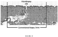
- This arrangement ensures that a significantly smaller cut is applied to the tissue as compared to conventional biopsy devices, (see Figure 10 for an illustration) and therefore minimises pain and scarring.
- the small cut means that only a small sample of biological material is taken. This enables many more samples to be taken across a larger area than is currently possible because suturing is unlikely to be necessary.
- the smaller sample size is also more easily disengaged from the surrounding tissue than a conventional large biopsy sample, meaning that it can be effectively automatically retained in the microbiopsy device's chamber after the sample is formed. This translates into a quicker and more efficient biopsy process than conventional multi step biopsies.
- the two or more opposed cutting elements are arranged to cut a section of tissue having a width of less than 750 microns.
- the two or more opposed cutting elements are arranged to cut a section of tissue having a width of less than 500 microns.
- the two or more opposed cutting elements are arranged to cut a section of tissue having a width of less than 400 microns.
- the two or more opposed cutting elements are arranged to cut a section of tissue having a width of less than 300 microns.
- the two or more opposed cutting elements are arranged to cut a section of tissue having a width of less than 200 microns.
- the two or more opposed cutting elements are arranged to cut a section of tissue having a width between 100 and 200 microns.
- the section of tissue is non circular.
- the section of tissue is substantially rectangular.
- the microbiopsy device has a modular design that can be customized for several different applications.
- the microbiopsy device can be assembled from plates having different functionalities-such as transparent outer plates that enable visual analysis of the sample in the chamber, or absorbent components included in the inner plates that can absorb biological fluids.
- the cutting elements of respective outer plates of the assembly are aligned.
- the inner plate/s include cutting elements which may be laterally spaced from the cutting elements of the outer plates.
- the chamber is defined by one or more recesses in the inner plate/s.
- the recesses are located between the cutting elements of the inner plate/s.
- the volume of the chamber of the microbiopsy device may be less than 5x10 -3 mm 3 , such as less than 3 x10 -3 mm 3 . In an embodiment, the volume is approximately 2 x10 -3 mm 3 such as 1.8x10 -3 mm 3 .
- the chamber retains the biological sample therein by friction.
- the chamber walls may have a surface roughness, R A , less than 25 ⁇ m.
- the surface roughness, R A may be greater than 1 ⁇ m. In an embodiment, the R A is greater than 5 ⁇ m. It has been found that the optimum surface roughness is a balance between sufficient roughness to frictionally retain the sample therein but not too much roughness such that the surface area available for sample collection in the chamber is significantly decreased.
- the microbiopsy device further includes retaining elements to retain the biological sample therein.
- the retaining elements comprises projections extending from one or more chamber walls.
- the projections may be provided at the opening of the chamber.
- the retaining elements comprise projections on one or more inner faces of the cutting elements.
- the chamber comprises a non-circular cross section. Without wishing to be limited by theory, it is thought that a non- circular cross section may be important for frictionally retaining a tissue sample in the chamber without the need for retaining elements.
- the chamber comprises a rectangular cross section. While the non-circular cross-section may have any number of sides, a four sided chamber is likely to be simpler to manufacture.
- the biological sample is tissue.
- the biological sample is a biological fluid, such as blood, plasma or serum.
- the chamber may contain a biological fluid capturing element, such as an absorbent material, and the biological fluid soaks into the chamber (typically over a period of seconds).
- the absorbent material may comprise a fibrous material (e.g. filter paper).
- the fibrous material may be impregnated with chemicals that would lyse cells, denature proteins, and/or protect DNA/RNA. Examples of such a material may be FTATM cards, polyethersulfone and Whatman (Grade 1) filter paper.
- the chamber may be at least partially open sided, for example, the device may include outer plates that include recesses therein to enable (physical and/or visual) access to the absorbent membrane.
- This embodiment of the microbiopsy device has applications in extracting serum samples from patients for example to characterise viral infections in vivo. After applying the microbiopsy device to a patient using an applicator (eg a plunger), the device can be detached from the applicator and either the absorbent material per se, or the entire device (plus absorbent material) can be placed into a tube containing a stabilising preservative (such as RNALater or PaxGene).
- a stabilising preservative such as RNALater or PaxGene
- the microbiopsy device can therefore be used as a minimally invasive means to procure samples for molecular diagnostics. This could be useful across the disease spectrum from viral, bacterial, fungal and protozoan infections.
- the microbiopsy device may be constructed from a biocompatible material.
- biocompatible is meant that the material does not cause a toxic, injurious, or adverse immunological response in living tissue.
- the material may be steel or a polymer of an appropriate medical grade.
- each plate comprises steel.
- the microbiopsy device comprises an insert for a punch biopsy applicator.
- the microbiopsy device includes a securing member for securing the plates in the assembly.
- the securing member comprises a clamp.
- a plurality of microbiopsy devices are provided in an array.
- the array may comprise devices arranged in columns and rows and can be used for example to take multiple samples simultaneously from skin.
- a method for making the microbiopsy device including the steps of providing at least two plates, each plate including a tapered section defining one or more respective cutting elements and at least one of the plates includes a recess therein, and forming an assembly of the plates such that the cutting elements are opposed and spaced from each other and together define a cutting end of the device for cutting tissue to form a biological sample, wherein the cutting elements are arranged to cut a section of tissue having a width of less than 1 mm; characterised in that the one or more recesses define a chamber having (a) an opening between the cutting elements and (b) a closed end and walls such that the retained biological sample is enclosed within the chamber except in the direction of the opening, wherein the chamber is defined by the one or more recesses in the plates.
- the method includes the step of forming the plates from a blank including panels corresponding to the plates.
- the step of forming the plates may comprise folding the blank between the panels.
- the step of forming the plates may comprise cutting the blank between the panels.
- the plates may be formed by laser cutting, moulding, die punching or chemical etching.
- the blank may include two or more panels, each panel may have at least one tapered section which forms one or more of the cutting elements upon assembly, and at least one panel may include a recess wherein the recess or recesses may define the chamber upon assembly.
- the invention in another aspect, relates to a blank for assembly into the microbiopsy device as described above, the blank including two or more panels, each panel having at least one tapered section, and at least one panel includes a recess, wherein upon assembly the tapered sections of the panels form at least two opposed, spaced cutting elements for cutting tissue to form a biological sample, wherein the cutting elements are arranged to cut a section of tissue having a width of less than 1 mm; characterised in that the recess or recesses of the two or more panels define a chamber for receiving and retaining the biological sample having (a) an opening between the cutting elements and (b) a closed end and walls such that a retained biological sample is enclosed within the chamber except in the direction of the opening between the cutting elements.
- the blank may comprise stainless steel.
- the microbiopsy device is formed by molding a plastics material.
- the plastics material may be a medically approved transparent polymer, such that the device can be used to remove a small piece of skin and then immediately image the sample (such as by reflectance confocal microscopy (RCM), multiphoton microscopy (MPM) or fluorescence lifetime imaging (FLIM) without further preparation.
- the polymer may need to be transparent to light from 350-900nm. Depending on the properties of the polymer, it may require additional structural support.
- the biological sample may be subsequently removed from the device for example by vortexing the device and sample.
- the microbiopsy device may penetrate skin to a depth of 200 ⁇ m or higher, such as to a minimum depth of 240 ⁇ m.
- the maximum penetration may exceed 300 ⁇ m, such as up to 370 ⁇ m.
- the microbiopsy device may be used in one or more methods for diagnosing, monitoring or treating a condition.
- the device may be used as follows: The microbiopsy device is applied to a patient's skin and extracts a tissue sample into the chamber. The device plus sample can then be placed into a Polymerase Chain Reaction (PCR) tube containing a nucleic acid stabilizer such as PAXgeneTM (path lab product) or RNAlater® (research lab product). The sample can then be subjected to molecular analysis for a range of conditions.
- PCR Polymerase Chain Reaction
- PAXgeneTM path lab product
- RNAlater® search lab product
- the small size of the microbiopsy device confers a number of significant benefits over conventional skin biopsy punches.
- the punch allows for 'suspicious' (potentially cancerous) skin lesions to be regularly sampled in order to diagnose or follow disease progression or to monitor therapeutic benefit.
- the punch can be used in a number of ways: Monitoring: The primary clinical application of the punch is as a screening tool for skin cancer.
- the punch is ideal for sampling naevi (chronic skin lesion - moles, birthmarks etc) for molecular changes across large skin areas. This allows greater sampling of suspicious lesions than what is possible with conventional large skin biopsy punches which have a cutting diameter of eg ⁇ 3mm. Each sample can be tested for a specific genetic mutation indicative of melanoma.
- sampled material can then be analysed using one or more of the following techniques: polymerase chain reaction, real-time PCR, next generation sequencing, RNASeq, Sanger sequencing, Southern blotting, Northern blotting, Western blotting, Enzyme linked immunoassay, microplate assay, probe hybridization assays, immunohistochemistry, automated protein analysis, 2-D PAGE analysis, microarray, bead based array and in situ hybridization.
- the punch can be used to aid the sampling of naevi to assess therapeutic success of a pharmacological intervention.
- the punch can also be used as a companion diagnostic in conjunction with specific therapeutics.
- NRAS The key melanoma related mutations that could be detected using molecular analysis are found in the NRAS oncogene and the proto-oncogene, BRAF. Both mutations appear to be mutually exclusive although they both affect the same downstream pathway through MAPK: NRAS.
- the most common NRAS mutations are in exon 2 at codon 61, specifically Q61L (leucine substitution for glutamine).
- the Q61 mutations result in a constitutively active form of the protein leading to uncontrolled cellular proliferation.
- BRAF is mutated in 40-60% of melanoma samples.
- the most common BRAF mutation is at codon 600, resulting in the substitution of glutamic acid for valine (V600E mutation).
- V600E mutation This mutation results in constitutive kinase activity of BRAF and subsequent downstream signalling through the MAP kinase pathway.
- the microbiopsy device is an ideal tool to use as a companion diagnostic with a therapeutic such as Zelboraf® (Vemurafenib, Genentech) which is a BRAF inhibitor that is able to block the function of the V600E-mutated BRAF protein.
- KIT a cell surface tyrosine kinase that plays a central role in normal melanocyte development
- PTEN a tumour suppressor gene involved in controlling cell cycle progression, cell growth and cell proliferation
- Biological samples extracted from 5 human (non-diseased) subjects using the microbiopsy device are of sufficient quality to enable their subsequent analysis using molecular tools such as PCR. Tests have shown, for example, that 20 +/- 8 ng of DNA and 28 +/- 6 ng of RNA can be extracted from the samples.,
- M1R melanocortin-1 receptor
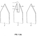
- FIG. 1(a) and Figure 1(b) a partial perspective view of a first embodiment of a microbiopsy device 10 for taking biological samples is shown.
- the microbiopsy device 10 comprises an assembly of three surgical grade stainless steel plates 20, 22, 24. The plates are clamped together (not shown) to jointly provide a body 12 from which extends four cutting elements 14, 15a, 15b and 16 which together provide a cutting end 19 for cutting tissue and forming a biological sample (such as a tissue sample). It may be noted that a different number of cutting elements may be provided in other embodiments.
- Two cutting elements, 14 and 16 comprise respective apices of tapered end sections on the outer plates 20 and 24.
- the other two cutting elements 15a and 15b each comprise a tapered end region on the inner plate 22.
- the cutting elements14 and 16 are axially aligned with each other.
- the cutting elements15a and 15b are laterally spaced from the cutting elements 14 and 16.
- the four cutting elements together define a substantially continuous cutting edge 26.
- a chamber 18 (shown in dotted outline in Figure 1(a) ) is provided inside the microbiopsy device10 for receiving and retaining the tissue sample (not shown).
- the chamber 18 has an opening 17 between the cutting elements 14, 15a, 15b and 16.
- the chamber is defined by a longitudinal recess between the cutting elements 15a and 15b in the inner plate 22. When the plates are assembled, the chamber 18 is therefore substantially rectangular in cross section.
- the cutting elements 14, 15a, 15b and 16 extend for a substantially similar distance from the body 12. This configuration ensures that the points of all four cutting elements contact the skin of a patient at the same time during a biopsy to thereby simultaneously apply points of pressure and result in a precise excision.
- the cutting elements 14, 15a, 15b and 16 are spaced from each other to enable cutting of a section of tissue with a width of less than 1 mm, such as less than 750 ⁇ m.
- cutting elements 14, 15a, 15b and 16 are inserted into tissue using a spring loaded applicator 42,( Figure 1 (c) ) . After the tissue is cut by cutting elements 14, 15a, 15b and 16, at least a portion of that tissue is received in the chamber 18 via the opening 17 and is retained in the chamber 18 by friction, as the microbiopsy device 10 is withdrawn from the tissue.
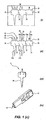
- Figure 1 (c) (i) to (iv) illustrate the formation and use of the first embodiment of a microbiopsy device 10 from a surgical grade stainless steel blank 30.
- Figure 1(c)(i) and (ii) show the laser cut blank 30 prior to and after, respectively, removal from a 0.05 mm thick steel sheet.
- the blank 30 comprises three panels 34, 36 and 38 which respectively include the plates 20, 24 and 22. The three panels are separated by lines 32 along which the panels can be folded or cut then assembled into the microbiopsy device 10, as shown in Figure 1(c)(iii) .
- Panels 34, 36 and 38 respectively include enlarged portions 35, 37 and 39.
- the enlarged portions 35 and 37 respectively include mounting stems 35a and 37a.
- Panel 34 also includes foldable flaps 40 located either side of plate 20 which can be folded over the shoulders 36a, 38a of panels 36 and 38 in order to secure the assembly of panels together.
- the enlarged portions 35, 37 and 39 overlap during assembly together form a mounting member 44 which is configured to be received in a spring loaded applicator 42 as shown in Figure 1 (c) (iv).
- the mounting member 44 is preferably ejectable from the applicator 42 after use.
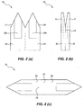
- the microbiopsy device 210 comprises two plates 220 and 224 including respective tapered end sections forming cutting elements 214 and 216.
- the end section of each plate is tapered depthwise as well as longitudinally.
- the thus formed cutting elements 220 and 224 are aligned with each other in the assembled biopsy device 210.
- the plates 220 and 224 include longitudinal channels 226a and 226b which together define a chamber 218 when the plates are assembled into the biopsy device 210.
- the microbiopsy device 210 can be assembled from a surgical grade stainless steel blank 230 that includes plates 220 and 224 and which has been produced by laser cutting. ( Figure 2(c) ). The device 210 can be assembled by cutting or folding the blank 230 along line 232 between the cutting elements.
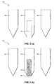
- Figure 3 schematically illustrates partial exploded views of two alternative embodiments of the microbiopsy device in which the plates would be overlaid to form the device.
- Figure 3 (a) shows a partial exploded view of a microbiopsy device 410 which includes an inner stainless steel plate 422 and two outer plates 420, 424 that each comprise transparent, medically approved glass or polymer, to facilitate visual inspection of the collected tissue in the chamber 418.
- the device 410 can be used to remove a small piece of skin and then immediately image the sample (such as by light microscopy, RCM, MPM or FLIM) without further preparation.
- Figure 3 (b) shows a further embodiment of a microbiopsy device 510 which includes two outer surgical grade stainless steel plates 520, 524 and an inner plate 522 that includes a chamber 518 in which is provided an absorbent membrane 560 for absorbing biological fluid, such as blood, plasma or serum, once the device is inserted into the skin.
- the inner plate 522 could be replaced entirely by a membrane of absorbent material.
- Figure 10 is a histological section showing the comparison in size between the skin sample taken by conventional biopsy and that taken by the microbiopsy device of the disclosure. The minimally invasive nature of the latter is clearly evident.
- Example 1 Chamber width and velocity of application.
- microbiopsy devices having varying chamber widths and application velocity with the 0.15 mm chamber configuration.
- Each microbiopsy device comprised 3x50 ⁇ m thick stainless steel plates with the chamber is defined by an elongate recess (channel) in the inner plate.
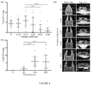
- Figure 4 (a) shows the total extracted DNA (ng) for each channel width at a velocity of 20.2 m/s.
- Figure 4 (b) shows that acceptable quantities of DNA were extracted at a channel width of 0.20 mm or lower when the device was applied at or over 16.6 m/s. The maximum amount of DNA was collected for a channel width of 0.15 mm.
- Figure 4 (c) shows high resolution scanning electron microscopic images of the microbiopsy devices having different channel widths in the inner plate.
- Example 2 a series of experiments were carried out to compare the amount of DNA extracted when a varied pre-application compression force was applied on the skin prior to using the microbiopsy devices. The experiments were conducted on one subject at 3 different forces. The pre-application skin compression forces that were tested were 0, 10 and 20N. In each case, the microbiopsy device comprised an assembly of three stainless steel plates, each plate being of 50 ⁇ m thickness. The impact velocity of the microbiopsy device was also kept constant at 15m/s in all the experiments.
- Figure 5 illustrates a graphical representation of the test results for Example 2. As shown in Figure 5 , a pre-application skin compression force of at least 10N was required to extract 4.5 ng of DNA. Furthermore, applying compression forces of greater than 10N did not lead to significant improvements in the amount of DNA extracted.
- Example 3 a series of experiments were carried out to compare the amount of DNA extracted when the surface roughness of the chamber walls was varied.
- Identical microbiopsy devices comprising an assembly of three stainless steel plates, each plate being 50 ⁇ m thick, were used.
- the total width of the chamber of the device used was kept constant at 150 ⁇ m. All other device parameters were also kept consistent.
- the impact velocity was kept constant at 15m/s and the pre-application skin compression force was also kept constant at 10N.
- microbiopsy devices having roughness amplitude (R A ) ranging from 5.36 to 23.70 were tested.
- the higher roughness amplitudes eg 23.70
- Chamber walls with a low roughness amplitude 0.92
- Example 3 Under the particular conditions of Example 3, it appeared that the optimal amount of sample retained in the chamber was at a surface roughness of around 6 ⁇ m of the chamber walls. Without wishing to be limited by theory, it is believed that there appear to be two opposing factors at work: the first factor being penetration depth of the cutting elements and the second factor being sample retention. It is theorized that rougher surface walls of the inner chamber will help to retain samples by friction but excessive roughness will reduce the surface area available for sample collection in the chamber.
- Example 4 Biological Fluid extracting Microbiopsy device
- a Microbiopsy device 610 was fabricated having a partially open-sided chamber in which was provided an absorbent membrane for taking a sample of serum ( Figure 7a to d ).
- the device included a 50 ⁇ m thick stainless steel plate 622 having a recess 618 therein in which was received a 100 ⁇ m thick porous membrane 660 ( Figure 7c & d ).
- the Microbiobsy device was applied to a patient's skin at a velocity of 6m/s and left for 2 minutes in vivo.
- Figures 7e &f show sera and blood absorbed into the membrane after removal of the device (7e&f, arrowhead in f). The sera was dried and stored for 2 days prior to running on a denaturing protein gel ( ⁇ P) with size markers (M) and stock sera (1 ⁇ l and 2 ⁇ l).
- ⁇ P denaturing protein gel
- M size markers
- Example 5 DNA extraction from melanoma lesions.
- Microbiopsy devices as illustrated in Figure 1 were used to take tissue samples from melanoma lesions in mice. Each microbiopsy device included an assembly of 3 plates, with the chamber being defined by a recess in the inner plate. Total DNA was extracted and PCR analysis of all samples detected the NRAS mutation indicative of melanoma in the lesions.
- Figure 8 (a) shows a clinical photographs of a 6 mm atypical naevus found on the lower back of a 88-years old male patient.
- the excised lesion was cut into halves ( Figure 8b ) and microbiopsies were taken on one half.
- the inset in Figure 8 (c) shows a tissue sample contained in the microbiopsy device taken using a benchtop scanning electron microscope. The sites of the microbiopsy application cannot be seen with the naked eye even at a higher magnification. The locations of the microbiopsy sites were marked with white crosses in Figure 8(d) .
- the site of microbiopsy was identified within the lesional region in the photomicrograph Figure 8(e) and the defect caused by the application of a microbiopsy demonstrated in a higher magnification photomicrograph ( Figure 8(f) was approximately 50 ⁇ m x 200 ⁇ m in size.
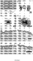
- Figure 9 a is a clinical photograph showing a 6 mm atypical naevus found on the upper back of a 56-years old female patient. Similarly, the excised lesion was cut into halves Figure 9(b) and microbiopsies were taken on one half Figure 9(c) . The sites of the microbiopsy application were also undetectable with the naked eye even at a higher magnification Figure 9(d) . The site of microbiopsy was outside the lesional region as shown in the photomicrograph Figure 9(e) and the defect caused by the application of a microbiopsy demonstrated in a higher magnification photomicrograph ( Figure 9 (f) ) was approximately 150 ⁇ m x 200 ⁇ m in size.
- the microbiopsy device was used to take tissue samples for use in live cell imaging, namely the ex vivo detection of reactive oxygen species (ROS).
- ROI reactive oxygen species
- Microbiopsy tissue capture enables rapid live tissue analysis.
- skin can be treated and the microbiopsy used to extract living skin cells for analysis.
- volunteers were treated with topical cosmetic products and microbiopsy material tested for the presence or absence of oxidative stress.
- the cosmetic products were nanoparticle containing sunscreens.
- Positive control samples including porcine stable - equine kidney (PSEK) cells and microbiopsy samples, were treated with tert-Butyl hydroperoxide (TBHP) at 200 ⁇ M for 60 mins to induce ROS. All microbiopsy samples were obtained from a single volunteer. The samples were treated with a fluorogenic DNA dye using manufacturer's protocol. A nuclei counterstain was applied to the samples 10 mins before the imaging. A Zeiss Meta510 confocal microscope was used to obtain these images.
- PSEK porcine stable - equine kidney
- TBHP tert-Butyl hydroperoxide
- This Example shows the potential of the microbiopsy device as a tool to perform live cell assay in volunteers and animal models.
Landscapes
- Health & Medical Sciences (AREA)
- Life Sciences & Earth Sciences (AREA)
- Engineering & Computer Science (AREA)
- General Health & Medical Sciences (AREA)
- Veterinary Medicine (AREA)
- Heart & Thoracic Surgery (AREA)
- Medical Informatics (AREA)
- Molecular Biology (AREA)
- Surgery (AREA)
- Animal Behavior & Ethology (AREA)
- Pathology (AREA)
- Public Health (AREA)
- Biomedical Technology (AREA)
- Hematology (AREA)
- Physics & Mathematics (AREA)
- Biophysics (AREA)
- Manufacturing & Machinery (AREA)
- Sampling And Sample Adjustment (AREA)
- Measuring Or Testing Involving Enzymes Or Micro-Organisms (AREA)
- Apparatus Associated With Microorganisms And Enzymes (AREA)
Claims (12)
- Dispositif de microbiopsie (10) pour le prélèvement d'échantillons biologiques, comprenant
un corps (12) comprenant un ensemble d'au moins deux plaques (20, 22, 24) incluant deux ou plus de deux éléments tranchants opposés et espacés (14, 15a, 15b, 16) permettant de trancher un tissu pour former un échantillon biologique, dans lequel les éléments tranchants prolongent une extrémité (19) du corps (12), chaque élément tranchant étant défini par une section effilée respective de l'une desdites plaques, et sont agencés pour trancher une section de tissu ayant une largeur de moins de 1 mm ;
dans lequel le dispositif comprend en outre une chambre (18) à l'intérieur du corps (12) pour recevoir et retenir l'échantillon biologique, la chambre ayant une ouverture (17) entre les éléments tranchants (14, 15a, 15b, 16) pour recevoir l'échantillon biologique ; caractérisé en ce que la chambre comprend en outre
une extrémité fermée et des parois telles que l'échantillon biologique retenu est enfermé au sein de la chambre à l'exception de la direction de l'ouverture (17), dans lequel la chambre est définie par un ou plusieurs évidements dans les plaques (20, 22, 24). - Dispositif de microbiopsie selon la revendication 1, dans lequel les deux ou plus de deux éléments tranchants opposés (14, 15a, 15b, 16) définissent ensemble au moins une arête tranchante (26).
- Dispositif de microbiopsie selon la revendication 1 ou la revendication 2, dans lequel les deux ou plus de deux éléments tranchants opposés (14, 15a, 15b, 16) sont agencés pour trancher une section de tissu ayant une largeur de moins de 750 microns, de préférence moins de 500 microns, de manière davantage préférée moins de 400 microns, de manière davantage préférée moins de 300 microns, de manière davantage préférée moins de 200 microns.
- Dispositif de microbiopsie selon une quelconque revendication précédente, dans lequel la chambre (18) y retient l'échantillon biologique par frottement, de préférence dans lequel au moins l'une des parois de la chambre a une rugosité de surface (RA) entre 1 micron et 25 microns, de préférence dans lequel un rapport de la rugosité de surface sur une distance entre au moins deux des deux ou plus de deux éléments tranchants opposés et espacés (14, 15a, 15b, 16) est de moins d'environ 0,15, de manière davantage préférée d'environ 0,04.
- Dispositif de microbiopsie selon une quelconque revendication précédente, dans lequel la chambre (18) a une section non circulaire.
- Dispositif de microbiopsie selon une quelconque revendication précédente, comprenant un ensemble de deux plaques (214, 216) et dans lequel la chambre contient un élément de capture de fluide biologique.
- Dispositif de microbiopsie selon une quelconque revendication précédente, dans lequel la chambre (18) a une largeur de 0,2 mm ou moins.
- Procédé de fabrication du dispositif de microbiopsie selon une quelconque revendication précédente, incluant les étapes :fourniture d'au moins deux plaques (20, 22, 24), chaque plaque ayant une section effilée définissant un ou plusieurs éléments tranchants respectifs (14, 15a, 15b, 16) et au moins une des plaques y renferme un évidement, etformation d'un ensemble des plaques telles que :les éléments tranchants sont opposés et espacés l'un de l'autre et définissent ensemble une extrémité tranchante (19) du dispositif pour trancher un tissu en vue de former un échantillon biologique, dans lequel les éléments tranchants sont agencés pour trancher une section de tissu ayant une largeur de moins de 1 mm ;dans lequel les un ou plusieurs évidements définissent une chambre (18) ayant une ouverture (17) entre les éléments tranchants ; caractérisé en ce que la chambre comprend en outre une extrémité fermée et des parois telles que l'échantillon biologique retenu est enfermé au sein de la chambre à l'exception de la direction de l'ouverture (17), dans lequel la chambre est définie par les un ou plusieurs évidements dans les plaques (20, 22, 24).
- Procédé selon la revendication 8, incluant en outre l'étape de formation des plaques à partir d'une ébauche incluant des panneaux correspondant aux plaques.
- Procédé selon la revendication 9, dans lequel l'étape de formation des plaques comprend le pliage ou la découpe de l'ébauche entre les panneaux.
- Ebauche (30, 230) pour assemblage dans le dispositif de microbiopsie selon l'une quelconque des revendications 1 à 10, l'ébauche incluant deux ou plus de deux panneaux (34, 36, 38, 220, 224),
chaque panneau ayant au moins une section effilée et au moins un panneau incluant un évidement, dans lequel lors de l'assemblage :les sections effilées des panneaux forment au moins deux éléments tranchants opposés et espacés (14, 15a, 15b, 16) pour trancher un tissu en vue de former un échantillon biologique, dans lequel les éléments tranchants sont agencés pour trancher une section de tissu ayant une largeur de moins de 1 mm ;dans lequel l'évidement ou les évidements des deux ou plus de deux panneaux définissent une chambre (18) destinée à recevoir et retenir l'échantillon biologique ayant une ouverture (17) entre les éléments tranchants ; caractérisé en ce que la chambre comprend en outre une extrémité fermée et des parois telles qu'un échantillon biologique retenu est enfermé au sein de la chambre à l'exception de la direction de l'ouverture (17) entre les éléments tranchants. - Ebauche selon la revendication 11, dans laquelle l'ébauche comprend de l'acier inoxydable.
Applications Claiming Priority (2)
| Application Number | Priority Date | Filing Date | Title |
|---|---|---|---|
| AU2012901490A AU2012901490A0 (en) | 2012-04-16 | A Microbiopsy device | |
| PCT/AU2013/000394 WO2013155557A1 (fr) | 2012-04-16 | 2013-04-16 | Dispositif de microbiopsie |
Publications (3)
| Publication Number | Publication Date |
|---|---|
| EP2838434A1 EP2838434A1 (fr) | 2015-02-25 |
| EP2838434A4 EP2838434A4 (fr) | 2015-05-06 |
| EP2838434B1 true EP2838434B1 (fr) | 2019-07-24 |
Family
ID=49382705
Family Applications (1)
| Application Number | Title | Priority Date | Filing Date |
|---|---|---|---|
| EP13778287.6A Active EP2838434B1 (fr) | 2012-04-16 | 2013-04-16 | Dispositif de microbiopsie |
Country Status (4)
| Country | Link |
|---|---|
| US (1) | US9662095B2 (fr) |
| EP (1) | EP2838434B1 (fr) |
| AU (1) | AU2013248930B2 (fr) |
| WO (1) | WO2013155557A1 (fr) |
Cited By (1)
| Publication number | Priority date | Publication date | Assignee | Title |
|---|---|---|---|---|
| US20220291130A1 (en) * | 2021-03-09 | 2022-09-15 | Nanyang Technological University | Diagnostic Device Based On Surface-Enhanced Raman Scattering |
Families Citing this family (10)
| Publication number | Priority date | Publication date | Assignee | Title |
|---|---|---|---|---|
| JP6426160B2 (ja) | 2013-06-05 | 2018-11-21 | エスエヌピーショット トラスティ— リミテッド | 組織試料採取における改良および組織試料採取に関連する改良 |
| WO2015056227A1 (fr) | 2013-10-18 | 2015-04-23 | Snpshot Trustee Limited | Collecteur pour biopsie avec identificateur |
| US20200038097A1 (en) * | 2018-07-31 | 2020-02-06 | Ethicon, Inc. | Kit for removing a tissue lesion |
| US20200038089A1 (en) | 2018-07-31 | 2020-02-06 | Ethicon, Inc. | Tissue resection apparatus |
| US12605150B2 (en) | 2019-07-16 | 2026-04-21 | Prana Thoracic, Inc. | Systems, devices, and methods for coring tissue |
| WO2021137746A1 (fr) | 2020-01-03 | 2021-07-08 | Roxhed Niclas | Dispositif de biopsie et procédé d'échantillonnage de tissu chez des mammifères |
| CA3179231A1 (fr) * | 2020-04-08 | 2021-10-14 | Bibbinstruments Ab | Instrument de biopsie, kit de pieces et procede |
| US12521168B2 (en) | 2020-06-08 | 2026-01-13 | Prana Thoracic, Inc. | Tissue resection control systems and methods |
| US20220214249A1 (en) * | 2021-01-06 | 2022-07-07 | The Board of Trustees of the Leland Stanford Junior University Office of the General Counsel, Bldg | Device for dicing biological tissue into fragments |
| US20240066070A1 (en) * | 2021-01-12 | 2024-02-29 | Agex Therapeutics, Inc. | Methods for the ex vivo induction of tissue regeneration in microbiopsies |
Citations (2)
| Publication number | Priority date | Publication date | Assignee | Title |
|---|---|---|---|---|
| US20060178598A1 (en) * | 2005-02-07 | 2006-08-10 | Seoul National University Industry Foundation | Three-dimensional micro spike and method of manufacturing the same |
| US20070106178A1 (en) * | 2002-12-03 | 2007-05-10 | Roe Steven N | Dual blade lancing test strip |
Family Cites Families (8)
| Publication number | Priority date | Publication date | Assignee | Title |
|---|---|---|---|---|
| US5928161A (en) | 1997-07-03 | 1999-07-27 | The Regents Of The University Of California | Microbiopsy/precision cutting devices |
| US7686770B2 (en) * | 2005-10-14 | 2010-03-30 | Microfabrica Inc. | Discrete or continuous tissue capture device and method for making |
| US20070219459A1 (en) | 2005-10-14 | 2007-09-20 | Microfabrica Inc. | Biopsy Devices, Methods for Using, and Methods for Making |
| WO2004010874A1 (fr) | 2002-07-26 | 2004-02-05 | Brown Stuart B | Dispositif d'echantillonnage de tissu et de fluide |
| TWI321589B (en) * | 2002-12-27 | 2010-03-11 | Ind Tech Res Inst | A dissecting device for cell and tissue aggregates |
| US20040175690A1 (en) * | 2003-03-03 | 2004-09-09 | Kci Licensing, Inc. | Tissue harvesting device and method |
| EP1977686A1 (fr) * | 2007-04-04 | 2008-10-08 | F.Hoffmann-La Roche Ag | Article de diagnostic à usage unique |
| US20120116322A1 (en) * | 2010-11-06 | 2012-05-10 | IntriMed Technologies, Inc. | Method to fabricate a needle having a tapered portion between a distal tip and a longitudinal channel |
-
2013
- 2013-04-16 EP EP13778287.6A patent/EP2838434B1/fr active Active
- 2013-04-16 AU AU2013248930A patent/AU2013248930B2/en active Active
- 2013-04-16 US US14/394,907 patent/US9662095B2/en active Active
- 2013-04-16 WO PCT/AU2013/000394 patent/WO2013155557A1/fr not_active Ceased
Patent Citations (2)
| Publication number | Priority date | Publication date | Assignee | Title |
|---|---|---|---|---|
| US20070106178A1 (en) * | 2002-12-03 | 2007-05-10 | Roe Steven N | Dual blade lancing test strip |
| US20060178598A1 (en) * | 2005-02-07 | 2006-08-10 | Seoul National University Industry Foundation | Three-dimensional micro spike and method of manufacturing the same |
Cited By (1)
| Publication number | Priority date | Publication date | Assignee | Title |
|---|---|---|---|---|
| US20220291130A1 (en) * | 2021-03-09 | 2022-09-15 | Nanyang Technological University | Diagnostic Device Based On Surface-Enhanced Raman Scattering |
Also Published As
| Publication number | Publication date |
|---|---|
| AU2013248930B2 (en) | 2018-08-09 |
| US20150112225A1 (en) | 2015-04-23 |
| WO2013155557A1 (fr) | 2013-10-24 |
| EP2838434A4 (fr) | 2015-05-06 |
| AU2013248930A1 (en) | 2014-12-04 |
| EP2838434A1 (fr) | 2015-02-25 |
| US9662095B2 (en) | 2017-05-30 |
Similar Documents
| Publication | Publication Date | Title |
|---|---|---|
| EP2838434B1 (fr) | Dispositif de microbiopsie | |
| EP2346410B1 (fr) | Instrument de biopsie pour l enrichissement d un matériau échantillon | |
| US11351551B2 (en) | Multi-well plate adaptors | |
| US11064982B2 (en) | Systems, devices and methods for tissue removal and analysis | |
| JP4510908B2 (ja) | 摘出物スライス補助装置及び摘出物スライス補助セット | |
| US20210204921A1 (en) | Microbiopsy device | |
| JP7609413B2 (ja) | 腎組織の蛍光イメージングによる解析方法 | |
| JP2011500285A (ja) | 組織分割生検針 | |
| Watanabe et al. | A dual wedge microneedle for sampling of perilymph solution via round window membrane | |
| EP1885740B1 (fr) | Extraction de proteines de tissu a fixation a la formaline | |
| EP3524957B1 (fr) | Gabarit de division de tissu | |
| US20090286305A1 (en) | Method for non-destructive macromolecule extraction from biological samples on slide | |
| US10231717B2 (en) | Biopsy needle | |
| US9023614B2 (en) | Method for collecting cells for macromolecular analysis | |
| US8642664B2 (en) | Composition for solubilizing tissue and cells comprising N-tetradecyl-N,N-dimethyl-3-ammonio-1-propanesulfonate and polyoxyethylene (10) cetyl ether | |
| US20150050683A1 (en) | Device And Method | |
| US20180161023A1 (en) | Dual-purpose biopsy punch | |
| EP1367380A1 (fr) | Méthode et dispositif pour la localisation et manipulation automatique de cellules | |
| Özden et al. | The long core needle with an end-cut technique for prostate biopsy: does it really have advantages when compared with standard needles? | |
| Fang et al. | A pilot study of using multiphoton microscopy to diagnose schwannoma | |
| Goldenberg et al. | Bedside Diagnostic Techniques in Dermatology | |
| EP2904976B1 (fr) | Instrument pour biopsie | |
| Lin | The skin microbiopsy | |
| US11247206B2 (en) | Harvesting cell-free non-coding RNAS (CFNCRS) from interstitial fluid for sensitive biomarkers | |
| EP1895018A2 (fr) | Procédé et moyen de mise en évidence de papillomavirus humains |
Legal Events
| Date | Code | Title | Description |
|---|---|---|---|
| PUAI | Public reference made under article 153(3) epc to a published international application that has entered the european phase |
Free format text: ORIGINAL CODE: 0009012 |
|
| 17P | Request for examination filed |
Effective date: 20141114 |
|
| AK | Designated contracting states |
Kind code of ref document: A1 Designated state(s): AL AT BE BG CH CY CZ DE DK EE ES FI FR GB GR HR HU IE IS IT LI LT LU LV MC MK MT NL NO PL PT RO RS SE SI SK SM TR |
|
| AX | Request for extension of the european patent |
Extension state: BA ME |
|
| RA4 | Supplementary search report drawn up and despatched (corrected) |
Effective date: 20150407 |
|
| RIC1 | Information provided on ipc code assigned before grant |
Ipc: A61B 10/02 20060101AFI20150330BHEP |
|
| DAX | Request for extension of the european patent (deleted) | ||
| STAA | Information on the status of an ep patent application or granted ep patent |
Free format text: STATUS: EXAMINATION IS IN PROGRESS |
|
| 17Q | First examination report despatched |
Effective date: 20170818 |
|
| GRAP | Despatch of communication of intention to grant a patent |
Free format text: ORIGINAL CODE: EPIDOSNIGR1 |
|
| STAA | Information on the status of an ep patent application or granted ep patent |
Free format text: STATUS: GRANT OF PATENT IS INTENDED |
|
| INTG | Intention to grant announced |
Effective date: 20190305 |
|
| GRAS | Grant fee paid |
Free format text: ORIGINAL CODE: EPIDOSNIGR3 |
|
| GRAA | (expected) grant |
Free format text: ORIGINAL CODE: 0009210 |
|
| STAA | Information on the status of an ep patent application or granted ep patent |
Free format text: STATUS: THE PATENT HAS BEEN GRANTED |
|
| AK | Designated contracting states |
Kind code of ref document: B1 Designated state(s): AL AT BE BG CH CY CZ DE DK EE ES FI FR GB GR HR HU IE IS IT LI LT LU LV MC MK MT NL NO PL PT RO RS SE SI SK SM TR |
|
| REG | Reference to a national code |
Ref country code: GB Ref legal event code: FG4D |
|
| REG | Reference to a national code |
Ref country code: CH Ref legal event code: EP |
|
| REG | Reference to a national code |
Ref country code: DE Ref legal event code: R096 Ref document number: 602013058229 Country of ref document: DE |
|
| REG | Reference to a national code |
Ref country code: AT Ref legal event code: REF Ref document number: 1157213 Country of ref document: AT Kind code of ref document: T Effective date: 20190815 |
|
| REG | Reference to a national code |
Ref country code: IE Ref legal event code: FG4D |
|
| REG | Reference to a national code |
Ref country code: NL Ref legal event code: MP Effective date: 20190724 |
|
| REG | Reference to a national code |
Ref country code: LT Ref legal event code: MG4D |
|
| REG | Reference to a national code |
Ref country code: AT Ref legal event code: MK05 Ref document number: 1157213 Country of ref document: AT Kind code of ref document: T Effective date: 20190724 |
|
| PG25 | Lapsed in a contracting state [announced via postgrant information from national office to epo] |
Ref country code: NO Free format text: LAPSE BECAUSE OF FAILURE TO SUBMIT A TRANSLATION OF THE DESCRIPTION OR TO PAY THE FEE WITHIN THE PRESCRIBED TIME-LIMIT Effective date: 20191024 Ref country code: BG Free format text: LAPSE BECAUSE OF FAILURE TO SUBMIT A TRANSLATION OF THE DESCRIPTION OR TO PAY THE FEE WITHIN THE PRESCRIBED TIME-LIMIT Effective date: 20191024 Ref country code: NL Free format text: LAPSE BECAUSE OF FAILURE TO SUBMIT A TRANSLATION OF THE DESCRIPTION OR TO PAY THE FEE WITHIN THE PRESCRIBED TIME-LIMIT Effective date: 20190724 Ref country code: AT Free format text: LAPSE BECAUSE OF FAILURE TO SUBMIT A TRANSLATION OF THE DESCRIPTION OR TO PAY THE FEE WITHIN THE PRESCRIBED TIME-LIMIT Effective date: 20190724 Ref country code: SE Free format text: LAPSE BECAUSE OF FAILURE TO SUBMIT A TRANSLATION OF THE DESCRIPTION OR TO PAY THE FEE WITHIN THE PRESCRIBED TIME-LIMIT Effective date: 20190724 Ref country code: LT Free format text: LAPSE BECAUSE OF FAILURE TO SUBMIT A TRANSLATION OF THE DESCRIPTION OR TO PAY THE FEE WITHIN THE PRESCRIBED TIME-LIMIT Effective date: 20190724 Ref country code: PT Free format text: LAPSE BECAUSE OF FAILURE TO SUBMIT A TRANSLATION OF THE DESCRIPTION OR TO PAY THE FEE WITHIN THE PRESCRIBED TIME-LIMIT Effective date: 20191125 Ref country code: HR Free format text: LAPSE BECAUSE OF FAILURE TO SUBMIT A TRANSLATION OF THE DESCRIPTION OR TO PAY THE FEE WITHIN THE PRESCRIBED TIME-LIMIT Effective date: 20190724 Ref country code: FI Free format text: LAPSE BECAUSE OF FAILURE TO SUBMIT A TRANSLATION OF THE DESCRIPTION OR TO PAY THE FEE WITHIN THE PRESCRIBED TIME-LIMIT Effective date: 20190724 |
|
| PG25 | Lapsed in a contracting state [announced via postgrant information from national office to epo] |
Ref country code: GR Free format text: LAPSE BECAUSE OF FAILURE TO SUBMIT A TRANSLATION OF THE DESCRIPTION OR TO PAY THE FEE WITHIN THE PRESCRIBED TIME-LIMIT Effective date: 20191025 Ref country code: ES Free format text: LAPSE BECAUSE OF FAILURE TO SUBMIT A TRANSLATION OF THE DESCRIPTION OR TO PAY THE FEE WITHIN THE PRESCRIBED TIME-LIMIT Effective date: 20190724 Ref country code: IS Free format text: LAPSE BECAUSE OF FAILURE TO SUBMIT A TRANSLATION OF THE DESCRIPTION OR TO PAY THE FEE WITHIN THE PRESCRIBED TIME-LIMIT Effective date: 20191124 Ref country code: RS Free format text: LAPSE BECAUSE OF FAILURE TO SUBMIT A TRANSLATION OF THE DESCRIPTION OR TO PAY THE FEE WITHIN THE PRESCRIBED TIME-LIMIT Effective date: 20190724 Ref country code: LV Free format text: LAPSE BECAUSE OF FAILURE TO SUBMIT A TRANSLATION OF THE DESCRIPTION OR TO PAY THE FEE WITHIN THE PRESCRIBED TIME-LIMIT Effective date: 20190724 Ref country code: AL Free format text: LAPSE BECAUSE OF FAILURE TO SUBMIT A TRANSLATION OF THE DESCRIPTION OR TO PAY THE FEE WITHIN THE PRESCRIBED TIME-LIMIT Effective date: 20190724 |
|
| PG25 | Lapsed in a contracting state [announced via postgrant information from national office to epo] |
Ref country code: TR Free format text: LAPSE BECAUSE OF FAILURE TO SUBMIT A TRANSLATION OF THE DESCRIPTION OR TO PAY THE FEE WITHIN THE PRESCRIBED TIME-LIMIT Effective date: 20190724 |
|
| PG25 | Lapsed in a contracting state [announced via postgrant information from national office to epo] |
Ref country code: IT Free format text: LAPSE BECAUSE OF FAILURE TO SUBMIT A TRANSLATION OF THE DESCRIPTION OR TO PAY THE FEE WITHIN THE PRESCRIBED TIME-LIMIT Effective date: 20190724 Ref country code: RO Free format text: LAPSE BECAUSE OF FAILURE TO SUBMIT A TRANSLATION OF THE DESCRIPTION OR TO PAY THE FEE WITHIN THE PRESCRIBED TIME-LIMIT Effective date: 20190724 Ref country code: DK Free format text: LAPSE BECAUSE OF FAILURE TO SUBMIT A TRANSLATION OF THE DESCRIPTION OR TO PAY THE FEE WITHIN THE PRESCRIBED TIME-LIMIT Effective date: 20190724 Ref country code: EE Free format text: LAPSE BECAUSE OF FAILURE TO SUBMIT A TRANSLATION OF THE DESCRIPTION OR TO PAY THE FEE WITHIN THE PRESCRIBED TIME-LIMIT Effective date: 20190724 Ref country code: PL Free format text: LAPSE BECAUSE OF FAILURE TO SUBMIT A TRANSLATION OF THE DESCRIPTION OR TO PAY THE FEE WITHIN THE PRESCRIBED TIME-LIMIT Effective date: 20190724 |
|
| PG25 | Lapsed in a contracting state [announced via postgrant information from national office to epo] |
Ref country code: IS Free format text: LAPSE BECAUSE OF FAILURE TO SUBMIT A TRANSLATION OF THE DESCRIPTION OR TO PAY THE FEE WITHIN THE PRESCRIBED TIME-LIMIT Effective date: 20200224 Ref country code: SK Free format text: LAPSE BECAUSE OF FAILURE TO SUBMIT A TRANSLATION OF THE DESCRIPTION OR TO PAY THE FEE WITHIN THE PRESCRIBED TIME-LIMIT Effective date: 20190724 Ref country code: SM Free format text: LAPSE BECAUSE OF FAILURE TO SUBMIT A TRANSLATION OF THE DESCRIPTION OR TO PAY THE FEE WITHIN THE PRESCRIBED TIME-LIMIT Effective date: 20190724 Ref country code: CZ Free format text: LAPSE BECAUSE OF FAILURE TO SUBMIT A TRANSLATION OF THE DESCRIPTION OR TO PAY THE FEE WITHIN THE PRESCRIBED TIME-LIMIT Effective date: 20190724 |
|
| REG | Reference to a national code |
Ref country code: DE Ref legal event code: R097 Ref document number: 602013058229 Country of ref document: DE |
|
| PLBE | No opposition filed within time limit |
Free format text: ORIGINAL CODE: 0009261 |
|
| STAA | Information on the status of an ep patent application or granted ep patent |
Free format text: STATUS: NO OPPOSITION FILED WITHIN TIME LIMIT |
|
| PG2D | Information on lapse in contracting state deleted |
Ref country code: IS |
|
| 26N | No opposition filed |
Effective date: 20200603 |
|
| PG25 | Lapsed in a contracting state [announced via postgrant information from national office to epo] |
Ref country code: SI Free format text: LAPSE BECAUSE OF FAILURE TO SUBMIT A TRANSLATION OF THE DESCRIPTION OR TO PAY THE FEE WITHIN THE PRESCRIBED TIME-LIMIT Effective date: 20190724 |
|
| PG25 | Lapsed in a contracting state [announced via postgrant information from national office to epo] |
Ref country code: MC Free format text: LAPSE BECAUSE OF FAILURE TO SUBMIT A TRANSLATION OF THE DESCRIPTION OR TO PAY THE FEE WITHIN THE PRESCRIBED TIME-LIMIT Effective date: 20190724 |
|
| REG | Reference to a national code |
Ref country code: CH Ref legal event code: PL |
|
| PG25 | Lapsed in a contracting state [announced via postgrant information from national office to epo] |
Ref country code: CH Free format text: LAPSE BECAUSE OF NON-PAYMENT OF DUE FEES Effective date: 20200430 Ref country code: LU Free format text: LAPSE BECAUSE OF NON-PAYMENT OF DUE FEES Effective date: 20200416 Ref country code: LI Free format text: LAPSE BECAUSE OF NON-PAYMENT OF DUE FEES Effective date: 20200430 |
|
| REG | Reference to a national code |
Ref country code: BE Ref legal event code: MM Effective date: 20200430 |
|
| PG25 | Lapsed in a contracting state [announced via postgrant information from national office to epo] |
Ref country code: BE Free format text: LAPSE BECAUSE OF NON-PAYMENT OF DUE FEES Effective date: 20200430 |
|
| PG25 | Lapsed in a contracting state [announced via postgrant information from national office to epo] |
Ref country code: IE Free format text: LAPSE BECAUSE OF NON-PAYMENT OF DUE FEES Effective date: 20200416 |
|
| PG25 | Lapsed in a contracting state [announced via postgrant information from national office to epo] |
Ref country code: MT Free format text: LAPSE BECAUSE OF FAILURE TO SUBMIT A TRANSLATION OF THE DESCRIPTION OR TO PAY THE FEE WITHIN THE PRESCRIBED TIME-LIMIT Effective date: 20190724 Ref country code: CY Free format text: LAPSE BECAUSE OF FAILURE TO SUBMIT A TRANSLATION OF THE DESCRIPTION OR TO PAY THE FEE WITHIN THE PRESCRIBED TIME-LIMIT Effective date: 20190724 |
|
| PG25 | Lapsed in a contracting state [announced via postgrant information from national office to epo] |
Ref country code: MK Free format text: LAPSE BECAUSE OF FAILURE TO SUBMIT A TRANSLATION OF THE DESCRIPTION OR TO PAY THE FEE WITHIN THE PRESCRIBED TIME-LIMIT Effective date: 20190724 |
|
| P01 | Opt-out of the competence of the unified patent court (upc) registered |
Effective date: 20230530 |
|
| PGFP | Annual fee paid to national office [announced via postgrant information from national office to epo] |
Ref country code: DE Payment date: 20250218 Year of fee payment: 13 |
|
| PGFP | Annual fee paid to national office [announced via postgrant information from national office to epo] |
Ref country code: GB Payment date: 20260303 Year of fee payment: 14 |
|
| PGFP | Annual fee paid to national office [announced via postgrant information from national office to epo] |
Ref country code: FR Payment date: 20260209 Year of fee payment: 14 |