EP2838603B1 - Medizinische leitungen mit einem distalen körper und einer offen gewickelten spirale - Google Patents
Medizinische leitungen mit einem distalen körper und einer offen gewickelten spirale Download PDFInfo
- Publication number
- EP2838603B1 EP2838603B1 EP13703969.9A EP13703969A EP2838603B1 EP 2838603 B1 EP2838603 B1 EP 2838603B1 EP 13703969 A EP13703969 A EP 13703969A EP 2838603 B1 EP2838603 B1 EP 2838603B1
- Authority
- EP
- European Patent Office
- Prior art keywords
- filar
- distal
- tine
- medical lead
- distal body
- Prior art date
- Legal status (The legal status is an assumption and is not a legal conclusion. Google has not performed a legal analysis and makes no representation as to the accuracy of the status listed.)
- Active
Links
Images




Classifications
-
- A—HUMAN NECESSITIES
- A61—MEDICAL OR VETERINARY SCIENCE; HYGIENE
- A61N—ELECTROTHERAPY; MAGNETOTHERAPY; RADIATION THERAPY; ULTRASOUND THERAPY
- A61N1/00—Electrotherapy; Circuits therefor
- A61N1/02—Details
- A61N1/04—Electrodes
- A61N1/05—Electrodes for implantation or insertion into the body, e.g. heart electrode
- A61N1/0551—Spinal or peripheral nerve electrodes
- A61N1/0558—Anchoring or fixation means therefor
-
- A—HUMAN NECESSITIES
- A61—MEDICAL OR VETERINARY SCIENCE; HYGIENE
- A61B—DIAGNOSIS; SURGERY; IDENTIFICATION
- A61B17/00—Surgical instruments, devices or methods
- A61B17/34—Trocars; Puncturing needles
- A61B17/3468—Trocars; Puncturing needles for implanting or removing devices, e.g. prostheses, implants, seeds, wires
-
- A—HUMAN NECESSITIES
- A61—MEDICAL OR VETERINARY SCIENCE; HYGIENE
- A61N—ELECTROTHERAPY; MAGNETOTHERAPY; RADIATION THERAPY; ULTRASOUND THERAPY
- A61N1/00—Electrotherapy; Circuits therefor
- A61N1/02—Details
- A61N1/04—Electrodes
- A61N1/05—Electrodes for implantation or insertion into the body, e.g. heart electrode
-
- A—HUMAN NECESSITIES
- A61—MEDICAL OR VETERINARY SCIENCE; HYGIENE
- A61N—ELECTROTHERAPY; MAGNETOTHERAPY; RADIATION THERAPY; ULTRASOUND THERAPY
- A61N1/00—Electrotherapy; Circuits therefor
- A61N1/02—Details
- A61N1/04—Electrodes
- A61N1/05—Electrodes for implantation or insertion into the body, e.g. heart electrode
- A61N1/056—Transvascular endocardial electrode systems
- A61N1/057—Anchoring means; Means for fixing the head inside the heart
Definitions
- Embodiments are related to medical leads that carry stimulation signals. More particularly, embodiments are related to medical leads that have a distal body and openly coiled filars.
- Medical leads arc used in conjunction with a medical device that generates stimulation signals to deliver the stimulation signals from the medical device to a target stimulation site within a body of a patient.
- the medical leads may be implanted through a percutaneous procedure where an introducer needle is inserted into the body, and a medical lead is inserted through a lumen in the needle.
- a stylet may be included within a lumen of the medical lead to guide the medical lead from the needle to the target site.
- the needle must be of adequate size to facilitate the introduction of the medical lead.
- a smaller needle is less bothersome to the patient.
- minimizing the diameter of the lead is desirable so that the size of the introducer needle may also be minimized.
- the medical lead needs to have a fixed position at the target site, which is particularly true when assessing the efficacy of therapy during a trial period. Movements by the patient may encourage the medical lead to migrate and therefore a fixation structure may be required to provide the fixation of the lead at the target site.
- the structure for fixation may contribute to the size of the medical lead which may call for an undesirable increase in the size of the introducer needle.
- explantation of the lead may be more difficult due to the presence of the fixation structure which resists movement in the direction of explantation.
- fixation structure may also be limited by the compliance of the body of the lead.
- the body of the lead needs a degree of firmness to support the electrodes and to maintain their alignment when at the target site. Yet a stiff lead body extending toward the proximal end of the lead is counterproductive to the fixation structure.
- Embodiments address issues such as these and others by providing a body that utilizes one or more openly coiled filars that act as a portion of the lead body and provides a relatively high degree of compliance.
- EP 0 972 538 A2 US 2007/255368 A1 and US 2007/0255369 A1 describe medical leads for providing medical electrical stimulation to a portion of a patient's nervous system.
- the invention is defined by the claims.
- a distal body present at the distal end of the coiled filar provides a firmer support for the electrodes. Tines on the proximal end offer fixation.
- the coiled filar may have a linear region proximal of the distal body, and the tines may collapse in the proximal direction to avoid increasing the diameter of the lead. Furthermore, the tines may collapse in the opposite direction when subject to a removal force during explantation.
- Embodiments provide a medical lead that includes a filar with an openly coiled center portion.
- the medical lead further includes a distal body having an electrode, with a distal portion of the filar passing through the distal body and being coupled to the electrode.
- the distal body has at least one tine on a proximal end.
- the filar has a linear distal end, the distal body being molded onto a distal portion of the linear distal end of the filar.
- a junction of the at least one tine to the distal body may provide a hinge point, the at least one tine being rotatable about the hinge point between a collapsed state and an extended state. The at least one tine may rotate in the proximal direction from the extended state to the collapsed state to become adjacent to the linear distal end of the coiled filar.
- Embodiments provide a medical system that includes a stimulation device and the medical lead with a proximal end coupled to the stimulation device.
- a method of positioning a medical lead that involves providing the medical lead having an openly coiled filar that has a linear distal end. The method further involves implanting the medical lead by routing the medical lead through a needle with the at least one tine in the collapsed state and with the at least one tine achieving the extended state upon exiting the needle. The method also involves explanting the medical lead by removing the lead in the proximal direction, wherein during exploiting the at least one tine rotates distally from the extended state to a second collapsed state where the at least one tine is adjacent to the distal body.
- Embodiments of medical leads include a compliant lead body formed by one or more openly coiled filars with a firmer distal body coupled to distal ends of the one or more filars.
- the distal body supports the electrodes, and some embodiments of the distal body may include proximal tines that collapse in the proximal direction to minimize the distal body diameter. Furthermore, in some embodiments the tines may collapse in the distal direction when the lead receives a removal force during explantation.
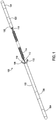
- FIGS. 1 and 2 show one example of a medical lead 100 having a central portion 114 of a filar that is openly coiled.
- the coiled filar is not surrounded by a protective tubular jacket but is instead itself the lead body.
- This openly coiled filar portion 114 provides a relatively high degree of compliance and elasticity for the lead 100.
- the filar may be constructed of various biocompatible conductors such as stainless steel alloys (316L, 316LVM, MP35N,etc.) or other biocompatible metals and alloys such as alloys of platinum (Pt-Ir) or alloys of titanium (TiOsteum ® , Ti-15Mo) that have a non-conductive coating such as polyethylene-co-tetrafluoroethylene (ETFE), polytetrafluoroethylene (PTFE or Teflon ® ), polyurethanes, polyimides, etc.
- the coiled shape defines a lumen 116 through which a stylet may be passed when implanting the medical lead 100.
- both a proximal filar portion 118 and a distal filar portion 112 are linear rather than coiled. These linear portions 112, 118 enter into respective distal and proximal bodies 102, 120. It will be appreciated that in other examples, one or both of these portions may be coiled as well, as in the example discussed below in relation to FIGS. 7 and 8 .
- the proximal body 120 of FIGS. 1 and 2 provides a firmer support for one or more contacts 122, 124 that are ultimately connected to a stimulation device.
- the proximal body 120 may be inserted into a bore within a stimulation device where the electrical connections occur.
- the proximal body 120 may be constructed of various nonconductive biocompatible materials such as polyurethane, polyether block amide (PEBA or PEBAX ® ), polyether ether ketone or polyaryletherketone (PEEK) and others.
- the proximal body 120 may define a lumen 128 that allows a stylet to be inserted during implantation of the medical lead 100.
- the proximal portion 118 of the filar(s) may extend through the proximal body 120 until reaching the respective contacts 122, 124. The proximal portion 118 of the filar(s) is then physically and electrically coupled to the respective contacts 122, 124.
- the distal body 102 provides a firmer support for one or more electrodes 104, 106 that are ultimately positioned at the target stimulation site within the body of the patient.
- the distal body 102 may be constructed of various nonconductive biocompatible materials such as polyurethane, silicone, and surface-modified endgroup (SME) polyurethanes to provide such firmness.
- the distal body 102 may define a lumen 126 that allows a stylet to be inserted when implanting the medical lead 100.
- the distal portion 112 of the filar(s) may extend through the distal body 102 until then coupling to the respective electrode 104, 106.
- the filar may be present within the lumen 126 or may otherwise tunnel through the distal body 102 until reaching the electrode 104, 106.
- the distal-most region of the distal filar portion 112 which is present within the lumen 126 may be coiled rather than linear, which provides an additional mechanical advantage during explantation to minimize strain on the bond of the filar portions 112 to the electrodes 104, 106.
- Another manner of minimizing such strain during explantation involves using a polyurethane coating directly on the metal of the filar portions 112 and then allowing the polyurethane coating to achieve a bond with the polymer forming the distal body 102.
- the distal body 102 may further define one or more proximal tines 108, 110. As shown in FIGS. 1 and 2 , two tines 108, 110 are present on opposite sides of the proximal end of the distal body 102 but any number of tines may be present in various embodiments. These tines have a natural extended state as shown in FIGS. 1 and 2 whereby the tines 108, 110 extend from the distal body 102 at a particular angle. In this extended state, the tines 108, 110 effectively catch upon the surrounding tissue of the body to resist movement in the proximal and distal directions.
- the amount of fixation force created by the tines 108, 110 can be controlled by the physical dimensions chosen for the tines 108, 110 including the angle, the length, the width, the thickness, and the geometry.
- the medical lead 100 may be selected for a particular implantation scenario based on having a tine design that meets the fixation requirements of the scenario.
- the distal body 102 and tines 108, 110 may be constructed by being molded onto the linear distal end 112 of the filars.
- An alternative construction would be to use tine and tubing components assembled manually and bonding them together with adhesives or thermally re-flowing the polymers together.
- the tines 108, 110 can be forced into a collapsed state where the tines 108, 110 are rotated proximally about a hinge point that occurs at the junction of the tines 108, 110 to the distal body 102 by insertion in the distal direction into a lumen of an introducer needle. Once fully rotated, the tines 108, 110 become adjacent to the linear distal portion 112 of the filar(s) so that the overall diameter of the medical lead is no greater than the diameter of the distal body 102. Therefore, the presence of the tines 108, 110 does not require an increase in size of the lumen of the introducer needle.
- the tines 108, 110 can be forced into a collapsed state where the tines 108, 110 are rotated distally to become adjacent to the distal body 102.
- the extraction force applied to the medical lead 102 is greater than the migration forces that the medical lead 102 is subject to such that the extraction force overcomes the natural reluctance of the tines 108, 110 to rotate distally from the extended state to this collapsed state.
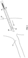
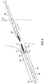
- FIGS. 3 and 4 One example of the process of implantation is shown in FIGS. 3 and 4 .
- the medical lead of FIG. 1 is located within a lumen of the introducer needle 136, and the tines 108, 110 are in the proximally collapsed state.
- the introducer needle 136 is inserted through the body 130 of the patient and directed toward a target stimulation site.
- the target stimulation site is in close proximity to the sacrum in order to stimulate nearby the sacral nerve.
- the electrodes 104, 106 may be positioned within a foramen 134 of the sacrum such that the needle 136 is directed to the foramen 134.
- the medical lead 100 is advanced distally from the needle 136 and through the foramen 134 by manipulation of a stylet 138 that is present within the lumens 116, 126, and 128 of the medical lead 100.
- the stylet 138 is used to steer the distal body 102 to the desired location relative to the sacral nerve.
- the tines 108, 110 naturally begin to rotate distally to the extended state.
- forward motion of the lead 100 by an insertion force from the stylet 138 overcomes any retention force being created by the tines 108, 110.
- the needle 136 and style 138 are then removed.
- FIG. 5 shows the medical lead 100 with the distal body 102 in the target site with the electrodes 104, 106 being in proximity to the sacral nerve.
- the tines 108, 110 are in their fully extended state and provide maximum resistance to further movements of the distal body 102.
- the openly coiled filar portion 114 extends proximally back to a location where a stimulation device 140 is being positioned with the proximal body 120 being coupled to the stimulation device 140.
- the stimulation device 140 is a trial stimulation device being positioned externally on the body 130 such that the filar portion 114 extends beyond the outer surface of the body 130.
- the stimulation device 140 may be implanted within a pocket formed within the body 130.
- a removal force is applied in the proximal direction to the proximal body 120 and the proximal end of the filar portion 114.
- This proximal force causes proximal movement of the distal body 102 which causes the tines 108, 110 to rotate distally until achieving the distally collapsed state as shown.
- the distal body 102 then proceeds proximally until exiting the body 130.
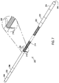
- FIGS. 7 and 8 show another example of a medical lead 200 having a central portion 214 of a filar that is openly coiled. Like the prior example, this openly coiled filar portion 214 provides a relatively high degree of compliance for the lead 200.
- the filar may be constructed of the same various biocompatible conductors with a non-conductive coating as the previous example.
- the coiled shape defines a lumen through which the stylet may be passed when implanting the medical lead 200.
- the filar portion 214 extends from a proximal body 220 to a distal body 202.
- the proximal body 220 provides a firmer support for one or more contacts 222, 224 that are ultimately connected to the stimulation device.
- the proximal body 220 may be inserted into a bore within the stimulation device where the electrical connections occur.
- the proximal body 220 may be constructed of the same various nonconductive biocompatible materials as the previous example.
- the proximal body 220 may define a lumen 228 that allows the stylet to be inserted during implantation of the medical lead 200.
- the filar(s) may extend through the proximal body 220 until reaching the respective contacts 222, 224. The filar(s) are then physically and electrically coupled to the respective contacts 222, 224.
- the distal body 202 provides a firmer support for one or more electrodes 204, 206 that are ultimately positioned at the target stimulation site within the body of the patient.
- the distal body 202 may be constructed of the same various nonconductive biocompatible materials such as the previous example to provide such firmness.
- the distal body 202 may define a lumen 226 that allows a stylet to be inserted when implanting the medical lead 200.
- the filar(s) may extend through the distal body 202 until then coupling to the respective electrode 204, 206.
- the filar may be present within the lumen 226 or may otherwise tunnel through the distal body 202 until reaching the electrode 204, 206.
- the distal-most region of the filars which is present within the lumen 226 may be coiled rather than linear, which provides an additional mechanical advantage during explantation to minimize strain on the bond of the filars to the electrodes 204, 206.
- Another manner of minimizing such strain during explantation involves using a polyurethane coating directly on the metal of the filars and then allowing the polyurethane coating to achieve a bond with the polymer forming the distal body 202.
- the distal body 202 may further define one or more proximal tines 208, 210. As shown in FIGS. 7 and 8 , two tines 208, 210 are present on opposite sides of the proximal end of the distal body 202 but any number of tines may be present in various embodiments. These tines 208, 210 have a natural extended state as shown in FIGS. 7 and 8 whereby the tines 208, 210 extend from the distal body 202 at a particular angle. In this extended state, the tines 208, 210 effectively catch upon the surrounding tissue of the body to resist movement in the axial proximal and distal directions.
- the distal body 202 and tines 208, 210 may be constructed in the same manner as discussed above for the embodiment of FIG.1
- the distal body 202 and tines 208, 210 may be molded onto the linear distal end 112 of the filars.
- An alternative construction would again be to use separate components (tines, tubings, etc.) assembled manually and bonding them together with adhesives or thermally re-flowing the polymers together.
- the tines 208, 210 can be forced into a collapsed state where the tines 208, 210 are rotated proximally about a hinge point that occurs at the junction of the tines 208, 210 to the distal body 202 by insertion in the distal direction into a lumen of the introducer needle. Once fully rotated, the tines 208, 210 become adjacent to the central portion 214 of the filar(s).
- the tines 208, 210 define an arced shape in a lateral dimension that rests on the arced lateral surface of the central portion 214.
- the presence of the tines 208, 210 does not require an increase in size of the lumen of the introducer needle.
- the tines 208, 210 can be forced into a collapsed state where the tines 208, 210 are rotated distally to become adjacent to the distal body 202.
- the extraction force applied to the medical lead 202 is greater than the migration forces that the medical lead 200 is subject to such that the extraction force overcomes the natural reluctance of the tines 208, 210 to rotate distally from the extended state to this collapsed state.
- the implantation of the medical lead 200 proceeds in the same manner discussed above in relation to FIGS. 3 and 4 .
- the explantation of the medical lead 200 proceeds in the same manner discussed above in relation to FIG. 6 .
Landscapes
- Health & Medical Sciences (AREA)
- Life Sciences & Earth Sciences (AREA)
- Public Health (AREA)
- Veterinary Medicine (AREA)
- Biomedical Technology (AREA)
- Nuclear Medicine, Radiotherapy & Molecular Imaging (AREA)
- Engineering & Computer Science (AREA)
- Heart & Thoracic Surgery (AREA)
- Animal Behavior & Ethology (AREA)
- General Health & Medical Sciences (AREA)
- Cardiology (AREA)
- Radiology & Medical Imaging (AREA)
- Surgery (AREA)
- Pathology (AREA)
- Medical Informatics (AREA)
- Molecular Biology (AREA)
- Neurology (AREA)
- Neurosurgery (AREA)
- Orthopedic Medicine & Surgery (AREA)
- Electrotherapy Devices (AREA)
Claims (10)
- Medizinische Leitung (100, 200), umfassend:einen Leitungskörper;einen Faden mit einem offen gewickelten Mittelabschnitt (114, 214), wobei der offen gewickelte Mittelabschnitt des Fadens ein gewickelter Abschnitt des Fadens ist, der nicht von einem röhrenförmigen Schutzmantel umgeben ist, sondern stattdessen selbst der Leitungskörper ist;einen distalen Körper (102, 202), der eine Elektrode (104, 106, 204, 206) aufweist, wobei ein distaler Abschnitt des Fadens durch den distalen Körper verläuft und mit der Elektrode gekoppelt ist, wobei der distale Körper wenigstens einen Zinken (108, 110, 208, 210) an einem proximalen Ende aufweist, wobei der Faden ein lineares distales Ende aufweist und wobei der distale Körper auf einen distalen Abschnitt des linearen distalen Endes des Faden geformt ist.
- Medizinische Leitung (100, 200) nach Anspruch 1, ferner umfassend einen proximalen Körper (120, 220), der von dem distalen Körper getrennt ist und einen Kontakt (122, 124, 222, 224) aufweist, wobei ein proximales Ende des Fadens durch den proximalen Körper verläuft und mit dem Kontakt gekoppelt ist.
- Medizinische Leitung (100, 200) nach einem der Ansprüche 1-2, wobei der Faden ein erster Faden ist und die Leitung ferner einen zweiten Faden mit einem offen gewickelten Mittelabschnitt umfasst, der mit dem ersten Faden gepaart ist, wobei der zweite Faden ein lineares distales Ende aufweist und wobei der distale Körper eine zweite Elektrode aufweist, die mit dem linearen distalen Ende des zweiten Fadens gekoppelt ist.
- Medizinische Leitung (100, 200) nach einem der Ansprüche 1-3, wobei eine Verbindung des wenigstens einen Zinkens mit dem distalen Körper einen Gelenkpunkt bereitstellt, wobei der wenigstens eine Zinken zwischen einem zusammengeklappten Zustand und einem ausgefahrenen Zustand um den Gelenkpunkt drehbar ist, wobei sich der wenigstens eine Zinken aus dem ausgefahrenen Zustand in den zusammengeklappten Zustand in die proximale Richtung dreht, um an das lineare distale Ende des Fadens angrenzend zu werden.
- Medizinische Leitung (100, 200) nach Anspruch 4, wobei der distale Abschnitt einen ersten (108, 208) und einen zweiten Zinken (208, 210) aufweist.
- Medizinische Leitung (100, 200) nach einem der Ansprüche 1-3, wobei der wenigstens eine Zinken eine gewölbte Form in einer lateralen Abmessung aufweist, wobei eine Verbindung des wenigstens einen Zinkens mit dem distalen Körper einen Gelenkpunkt bereitstellt, wobei der wenigstens eine Zinken zwischen einem zusammengeklappten Zustand und einem ausgefahrenen Zustand um den Gelenkpunkt drehbar ist, wobei sich der wenigstens einen Zinken aus dem ausgefahrenen Zustand in den zusammengeklappten Zustand in die proximale Richtung dreht, um an den gewickelten Faden angrenzend zu werden.
- Medizinische Leitung (100, 200) nach einem der Ansprüche 1-3, wobei ein distaler Abschnitt des linearen distalen Endes des Fadens durch den distalen Körper verläuft und mit der Elektrode gekoppelt ist, wobei eine Verbindung des wenigstens einen Zinkens mit dem distalen Körper einen Gelenkpunkt bereitstellt, wobei der wenigstens eine Zinken zwischen einem zusammengeklappten Zustand und einem ausgefahrenen Zustand um den Gelenkpunkt drehbar ist, wobei sich der wenigstens eine Zinken aus dem ausgefahrenen Zustand in den zusammengeklappten Zustand in die proximale Richtung dreht, um an das lineare distale Ende des Fadens angrenzend zu werden.
- Medizinische Leitung (100, 200) nach Anspruch 7, wobei der distale Abschnitt einen ersten (108, 208) und einen zweiten Zinken (110, 210) aufweist.
- Medizinische Leitung (100, 200) nach Anspruch 8, wobei der erste Zinken (108, 208) und der zweite Zinken (110, 210) auf gegenüberliegenden Seiten des distalen Körpers positioniert sind.
- Medizinisches System, Folgendes umfassend:eine Stimulationsvorrichtung (140); undeine medizinische Leitung (100, 200) nach einem der Ansprüche 7-9, wobei ein proximales Ende mit der Stimulationsvorrichtung gekoppelt ist.
Applications Claiming Priority (2)
| Application Number | Priority Date | Filing Date | Title |
|---|---|---|---|
| US201261635798P | 2012-04-19 | 2012-04-19 | |
| PCT/US2013/023626 WO2013158188A1 (en) | 2012-04-19 | 2013-01-29 | Medical leads having a distal body and an openly coiled filar |
Publications (2)
| Publication Number | Publication Date |
|---|---|
| EP2838603A1 EP2838603A1 (de) | 2015-02-25 |
| EP2838603B1 true EP2838603B1 (de) | 2021-12-15 |
Family
ID=47710344
Family Applications (1)
| Application Number | Title | Priority Date | Filing Date |
|---|---|---|---|
| EP13703969.9A Active EP2838603B1 (de) | 2012-04-19 | 2013-01-29 | Medizinische leitungen mit einem distalen körper und einer offen gewickelten spirale |
Country Status (3)
| Country | Link |
|---|---|
| US (2) | US10086191B2 (de) |
| EP (1) | EP2838603B1 (de) |
| WO (1) | WO2013158188A1 (de) |
Families Citing this family (18)
| Publication number | Priority date | Publication date | Assignee | Title |
|---|---|---|---|---|
| WO2014146016A2 (en) | 2013-03-15 | 2014-09-18 | Alfred E. Mann Foundation For Scientific Research | Current sensing multiple output current stimulators with fast turn on time |
| CA3075310C (en) | 2013-07-29 | 2022-04-05 | Alfred E. Mann Foundation For Scientific Research | Microprocessor controlled class e driver |
| EP3180072B1 (de) | 2014-08-15 | 2018-11-28 | Axonics Modulation Technologies Inc. | Positionierung einer elektromyografischen elektrode und stimulationstitrierung in einem nervenstimulierungssystem zur behandlung von hyperaktiver blase |
| WO2016025915A1 (en) | 2014-08-15 | 2016-02-18 | Axonics Modulation Technologies, Inc. | Integrated electromyographic clinician programmer for use with an implantable neurostimulator |
| CN106659882A (zh) | 2014-08-15 | 2017-05-10 | 艾克索尼克斯调制技术股份有限公司 | 用于进行神经刺激以减轻膀胱功能障碍和其他适应症的可植入引线附着结构 |
| US9855423B2 (en) | 2014-08-15 | 2018-01-02 | Axonics Modulation Technologies, Inc. | Systems and methods for neurostimulation electrode configurations based on neural localization |
| EP3180071B1 (de) | 2014-08-15 | 2021-09-22 | Axonics, Inc. | Externe impulsgeneratorvorrichtung und zugehörige system zur versuchsnervenstimulation |
| CN107427685B (zh) | 2015-01-09 | 2021-09-21 | 艾克索尼克斯股份有限公司 | 与神经刺激充电设备一起使用的附接设备及相关联方法 |
| EP3242718B1 (de) | 2015-01-09 | 2019-05-08 | Axonics Modulation Technologies, Inc. | Verbesserte antenne und verfahren zur verwendung von implantierbarem nervenstimulator |
| AU2016205047B2 (en) | 2015-01-09 | 2020-07-02 | Axonics Modulation Technologies, Inc. | Patient remote and associated methods of use with a nerve stimulation system |
| CN107847731B (zh) | 2015-07-10 | 2019-06-28 | 艾克索尼克斯调制技术股份有限公司 | 具有无asic的内部电子设备的可植入神经刺激器以及使用方法 |
| WO2017132374A1 (en) | 2016-01-29 | 2017-08-03 | Axonics Modulation Technologies, Inc. | Methods and systems for frequency adjustment to optimize charging of implantable neurostimulator |
| CN108697897B (zh) | 2016-02-12 | 2023-01-13 | 艾克索尼克斯股份有限公司 | 用于试验神经刺激的外部脉冲发生器设备和相关联方法 |
| CN111741789B (zh) | 2018-02-22 | 2024-07-05 | 艾克索尼克斯股份有限公司 | 用于试验神经刺激的神经刺激引线和使用方法 |
| US11642537B2 (en) | 2019-03-11 | 2023-05-09 | Axonics, Inc. | Charging device with off-center coil |
| US11439829B2 (en) | 2019-05-24 | 2022-09-13 | Axonics, Inc. | Clinician programmer methods and systems for maintaining target operating temperatures |
| US11848090B2 (en) | 2019-05-24 | 2023-12-19 | Axonics, Inc. | Trainer for a neurostimulator programmer and associated methods of use with a neurostimulation system |
| US12420103B1 (en) | 2020-08-20 | 2025-09-23 | Axonics, Inc. | Neurostimulation leads with reduced current leakage |
Family Cites Families (15)
| Publication number | Priority date | Publication date | Assignee | Title |
|---|---|---|---|---|
| US4506679A (en) * | 1982-09-30 | 1985-03-26 | Mann Alfred E | Endocardial electrode |
| US4945922A (en) * | 1989-03-13 | 1990-08-07 | Vitatron Medical B.V. | Pacing lead |
| US5571157A (en) | 1995-07-19 | 1996-11-05 | Pacesetter, Inc. | Endocardial lead with reduced diameter tip portion and method for making such lead |
| US6104960A (en) * | 1998-07-13 | 2000-08-15 | Medtronic, Inc. | System and method for providing medical electrical stimulation to a portion of the nervous system |
| US6240322B1 (en) | 1998-11-04 | 2001-05-29 | Cardiac Pacemakers, Inc. | System and apparatus having low profile collapsible tines |
| AU6953300A (en) | 1999-07-07 | 2001-01-22 | Cardiac Pacemakers, Inc. | Endocardial electrode assembly having conductive fixation features |
| US6999819B2 (en) | 2001-08-31 | 2006-02-14 | Medtronic, Inc. | Implantable medical electrical stimulation lead fixation method and apparatus |
| US8135476B2 (en) * | 2006-04-27 | 2012-03-13 | Medtronic, Inc. | Implantable medical electrical stimulation lead fixation method and apparatus |
| US8892214B2 (en) * | 2006-04-28 | 2014-11-18 | Medtronic, Inc. | Multi-electrode peripheral nerve evaluation lead and related system and method of use |
| US20070255368A1 (en) | 2006-04-28 | 2007-11-01 | Bonde Eric H | Implantable medical electrical stimulation lead with distal fixation and method |
| US7881783B2 (en) | 2006-04-28 | 2011-02-01 | Medtronics, Inc. | Implantable medical electrical stimulation lead, such as a PNE lead, and method of use |
| AU2008210504B2 (en) * | 2007-01-29 | 2012-07-26 | Spinal Modulation, Inc. | Sutureless lead retention features |
| US8335570B2 (en) * | 2008-10-09 | 2012-12-18 | Boston Scientific Neuromodulation Corporation | Electrical stimulation leads having RF compatibility and methods of use and manufacture |
| US9387323B2 (en) | 2009-09-23 | 2016-07-12 | Lake Region Manufacturing, Inc. | Guidewire-style pacing lead |
| US8478425B2 (en) * | 2010-03-31 | 2013-07-02 | Medtronic, Inc. | Medical leads and related systems that include a lumen body that is joined to a lead body and that has multiple filar lumens |
-
2013
- 2013-01-29 EP EP13703969.9A patent/EP2838603B1/de active Active
- 2013-01-29 WO PCT/US2013/023626 patent/WO2013158188A1/en not_active Ceased
- 2013-01-29 US US14/395,247 patent/US10086191B2/en active Active
-
2018
- 2018-09-24 US US16/139,641 patent/US11013915B2/en active Active
Also Published As
| Publication number | Publication date |
|---|---|
| US10086191B2 (en) | 2018-10-02 |
| US20190022374A1 (en) | 2019-01-24 |
| US11013915B2 (en) | 2021-05-25 |
| US20150133955A1 (en) | 2015-05-14 |
| EP2838603A1 (de) | 2015-02-25 |
| WO2013158188A1 (en) | 2013-10-24 |
Similar Documents
| Publication | Publication Date | Title |
|---|---|---|
| US11013915B2 (en) | Medical leads having a distal body and an openly coiled filar | |
| US8738153B2 (en) | Implantable lead with braided conductors | |
| US11160974B2 (en) | Neurostimulation lead with stiffened proximal array | |
| CN113747936B (zh) | 用于电刺激来治疗癌症的电极 | |
| US9510857B2 (en) | System and method for making and using a lead introducer for an implantable electrical stimulation system | |
| US10398890B2 (en) | Introduction of medical lead into patient | |
| US9700350B2 (en) | Systems and methods for making and using a lead introducer for an implantable electrical stimulation system | |
| US8112159B2 (en) | Kit for implantation of therapy elements | |
| US7532939B2 (en) | Active fixation medical lead | |
| EP2564892A1 (de) | Leitungskörper mit koaxialen Innen- und Außenspulen | |
| CN113677391B (zh) | 用于电疗和/或电生理学的装置、套件和组件 | |
| CN110975145A (zh) | 用于通过经血管神经刺激辅助呼吸的装置和方法 | |
| US8868209B2 (en) | Fixation mechanisms for temporary implantable medical electrical stimulation leads | |
| US9604050B2 (en) | Systems and methods for percutaneously implanting into a patient a paddle lead of an electrical stimulation system | |
| US20160158539A1 (en) | Acutely stiff implantable electrodes | |
| US7672735B2 (en) | Two-part implantable cardiac lead | |
| WO2008055025A1 (en) | Medical lead delivery device | |
| US8694125B2 (en) | Medical leads having a distal body and an openly coiled filar | |
| JP2025501333A (ja) | 電気療法及び/又は電気生理学のための装置並びに方法 |
Legal Events
| Date | Code | Title | Description |
|---|---|---|---|
| PUAI | Public reference made under article 153(3) epc to a published international application that has entered the european phase |
Free format text: ORIGINAL CODE: 0009012 |
|
| 17P | Request for examination filed |
Effective date: 20141117 |
|
| AK | Designated contracting states |
Kind code of ref document: A1 Designated state(s): AL AT BE BG CH CY CZ DE DK EE ES FI FR GB GR HR HU IE IS IT LI LT LU LV MC MK MT NL NO PL PT RO RS SE SI SK SM TR |
|
| AX | Request for extension of the european patent |
Extension state: BA ME |
|
| DAX | Request for extension of the european patent (deleted) | ||
| STAA | Information on the status of an ep patent application or granted ep patent |
Free format text: STATUS: EXAMINATION IS IN PROGRESS |
|
| 17Q | First examination report despatched |
Effective date: 20171031 |
|
| GRAP | Despatch of communication of intention to grant a patent |
Free format text: ORIGINAL CODE: EPIDOSNIGR1 |
|
| STAA | Information on the status of an ep patent application or granted ep patent |
Free format text: STATUS: GRANT OF PATENT IS INTENDED |
|
| INTG | Intention to grant announced |
Effective date: 20210203 |
|
| GRAJ | Information related to disapproval of communication of intention to grant by the applicant or resumption of examination proceedings by the epo deleted |
Free format text: ORIGINAL CODE: EPIDOSDIGR1 |
|
| STAA | Information on the status of an ep patent application or granted ep patent |
Free format text: STATUS: EXAMINATION IS IN PROGRESS |
|
| INTC | Intention to grant announced (deleted) | ||
| GRAP | Despatch of communication of intention to grant a patent |
Free format text: ORIGINAL CODE: EPIDOSNIGR1 |
|
| STAA | Information on the status of an ep patent application or granted ep patent |
Free format text: STATUS: GRANT OF PATENT IS INTENDED |
|
| INTG | Intention to grant announced |
Effective date: 20210715 |
|
| GRAS | Grant fee paid |
Free format text: ORIGINAL CODE: EPIDOSNIGR3 |
|
| GRAA | (expected) grant |
Free format text: ORIGINAL CODE: 0009210 |
|
| STAA | Information on the status of an ep patent application or granted ep patent |
Free format text: STATUS: THE PATENT HAS BEEN GRANTED |
|
| AK | Designated contracting states |
Kind code of ref document: B1 Designated state(s): AL AT BE BG CH CY CZ DE DK EE ES FI FR GB GR HR HU IE IS IT LI LT LU LV MC MK MT NL NO PL PT RO RS SE SI SK SM TR |
|
| REG | Reference to a national code |
Ref country code: GB Ref legal event code: FG4D Ref country code: CH Ref legal event code: EP |
|
| REG | Reference to a national code |
Ref country code: IE Ref legal event code: FG4D Ref country code: DE Ref legal event code: R096 Ref document number: 602013080406 Country of ref document: DE |
|
| REG | Reference to a national code |
Ref country code: AT Ref legal event code: REF Ref document number: 1455016 Country of ref document: AT Kind code of ref document: T Effective date: 20220115 |
|
| REG | Reference to a national code |
Ref country code: LT Ref legal event code: MG9D |
|
| REG | Reference to a national code |
Ref country code: NL Ref legal event code: MP Effective date: 20211215 |
|
| PG25 | Lapsed in a contracting state [announced via postgrant information from national office to epo] |
Ref country code: RS Free format text: LAPSE BECAUSE OF FAILURE TO SUBMIT A TRANSLATION OF THE DESCRIPTION OR TO PAY THE FEE WITHIN THE PRESCRIBED TIME-LIMIT Effective date: 20211215 Ref country code: LT Free format text: LAPSE BECAUSE OF FAILURE TO SUBMIT A TRANSLATION OF THE DESCRIPTION OR TO PAY THE FEE WITHIN THE PRESCRIBED TIME-LIMIT Effective date: 20211215 Ref country code: FI Free format text: LAPSE BECAUSE OF FAILURE TO SUBMIT A TRANSLATION OF THE DESCRIPTION OR TO PAY THE FEE WITHIN THE PRESCRIBED TIME-LIMIT Effective date: 20211215 Ref country code: BG Free format text: LAPSE BECAUSE OF FAILURE TO SUBMIT A TRANSLATION OF THE DESCRIPTION OR TO PAY THE FEE WITHIN THE PRESCRIBED TIME-LIMIT Effective date: 20220315 |
|
| REG | Reference to a national code |
Ref country code: AT Ref legal event code: MK05 Ref document number: 1455016 Country of ref document: AT Kind code of ref document: T Effective date: 20211215 |
|
| PG25 | Lapsed in a contracting state [announced via postgrant information from national office to epo] |
Ref country code: SE Free format text: LAPSE BECAUSE OF FAILURE TO SUBMIT A TRANSLATION OF THE DESCRIPTION OR TO PAY THE FEE WITHIN THE PRESCRIBED TIME-LIMIT Effective date: 20211215 Ref country code: NO Free format text: LAPSE BECAUSE OF FAILURE TO SUBMIT A TRANSLATION OF THE DESCRIPTION OR TO PAY THE FEE WITHIN THE PRESCRIBED TIME-LIMIT Effective date: 20220315 Ref country code: LV Free format text: LAPSE BECAUSE OF FAILURE TO SUBMIT A TRANSLATION OF THE DESCRIPTION OR TO PAY THE FEE WITHIN THE PRESCRIBED TIME-LIMIT Effective date: 20211215 Ref country code: HR Free format text: LAPSE BECAUSE OF FAILURE TO SUBMIT A TRANSLATION OF THE DESCRIPTION OR TO PAY THE FEE WITHIN THE PRESCRIBED TIME-LIMIT Effective date: 20211215 Ref country code: GR Free format text: LAPSE BECAUSE OF FAILURE TO SUBMIT A TRANSLATION OF THE DESCRIPTION OR TO PAY THE FEE WITHIN THE PRESCRIBED TIME-LIMIT Effective date: 20220316 |
|
| PG25 | Lapsed in a contracting state [announced via postgrant information from national office to epo] |
Ref country code: NL Free format text: LAPSE BECAUSE OF FAILURE TO SUBMIT A TRANSLATION OF THE DESCRIPTION OR TO PAY THE FEE WITHIN THE PRESCRIBED TIME-LIMIT Effective date: 20211215 |
|
| PG25 | Lapsed in a contracting state [announced via postgrant information from national office to epo] |
Ref country code: SM Free format text: LAPSE BECAUSE OF FAILURE TO SUBMIT A TRANSLATION OF THE DESCRIPTION OR TO PAY THE FEE WITHIN THE PRESCRIBED TIME-LIMIT Effective date: 20211215 Ref country code: SK Free format text: LAPSE BECAUSE OF FAILURE TO SUBMIT A TRANSLATION OF THE DESCRIPTION OR TO PAY THE FEE WITHIN THE PRESCRIBED TIME-LIMIT Effective date: 20211215 Ref country code: RO Free format text: LAPSE BECAUSE OF FAILURE TO SUBMIT A TRANSLATION OF THE DESCRIPTION OR TO PAY THE FEE WITHIN THE PRESCRIBED TIME-LIMIT Effective date: 20211215 Ref country code: PT Free format text: LAPSE BECAUSE OF FAILURE TO SUBMIT A TRANSLATION OF THE DESCRIPTION OR TO PAY THE FEE WITHIN THE PRESCRIBED TIME-LIMIT Effective date: 20220418 Ref country code: ES Free format text: LAPSE BECAUSE OF FAILURE TO SUBMIT A TRANSLATION OF THE DESCRIPTION OR TO PAY THE FEE WITHIN THE PRESCRIBED TIME-LIMIT Effective date: 20211215 Ref country code: EE Free format text: LAPSE BECAUSE OF FAILURE TO SUBMIT A TRANSLATION OF THE DESCRIPTION OR TO PAY THE FEE WITHIN THE PRESCRIBED TIME-LIMIT Effective date: 20211215 Ref country code: CZ Free format text: LAPSE BECAUSE OF FAILURE TO SUBMIT A TRANSLATION OF THE DESCRIPTION OR TO PAY THE FEE WITHIN THE PRESCRIBED TIME-LIMIT Effective date: 20211215 |
|
| PG25 | Lapsed in a contracting state [announced via postgrant information from national office to epo] |
Ref country code: PL Free format text: LAPSE BECAUSE OF FAILURE TO SUBMIT A TRANSLATION OF THE DESCRIPTION OR TO PAY THE FEE WITHIN THE PRESCRIBED TIME-LIMIT Effective date: 20211215 Ref country code: AT Free format text: LAPSE BECAUSE OF FAILURE TO SUBMIT A TRANSLATION OF THE DESCRIPTION OR TO PAY THE FEE WITHIN THE PRESCRIBED TIME-LIMIT Effective date: 20211215 |
|
| REG | Reference to a national code |
Ref country code: CH Ref legal event code: PL |
|
| REG | Reference to a national code |
Ref country code: DE Ref legal event code: R097 Ref document number: 602013080406 Country of ref document: DE |
|
| PG25 | Lapsed in a contracting state [announced via postgrant information from national office to epo] |
Ref country code: MC Free format text: LAPSE BECAUSE OF FAILURE TO SUBMIT A TRANSLATION OF THE DESCRIPTION OR TO PAY THE FEE WITHIN THE PRESCRIBED TIME-LIMIT Effective date: 20211215 Ref country code: IS Free format text: LAPSE BECAUSE OF FAILURE TO SUBMIT A TRANSLATION OF THE DESCRIPTION OR TO PAY THE FEE WITHIN THE PRESCRIBED TIME-LIMIT Effective date: 20220415 |
|
| REG | Reference to a national code |
Ref country code: BE Ref legal event code: MM Effective date: 20220131 |
|
| PLBE | No opposition filed within time limit |
Free format text: ORIGINAL CODE: 0009261 |
|
| STAA | Information on the status of an ep patent application or granted ep patent |
Free format text: STATUS: NO OPPOSITION FILED WITHIN TIME LIMIT |
|
| PG25 | Lapsed in a contracting state [announced via postgrant information from national office to epo] |
Ref country code: LU Free format text: LAPSE BECAUSE OF NON-PAYMENT OF DUE FEES Effective date: 20220129 Ref country code: DK Free format text: LAPSE BECAUSE OF FAILURE TO SUBMIT A TRANSLATION OF THE DESCRIPTION OR TO PAY THE FEE WITHIN THE PRESCRIBED TIME-LIMIT Effective date: 20211215 Ref country code: AL Free format text: LAPSE BECAUSE OF FAILURE TO SUBMIT A TRANSLATION OF THE DESCRIPTION OR TO PAY THE FEE WITHIN THE PRESCRIBED TIME-LIMIT Effective date: 20211215 |
|
| 26N | No opposition filed |
Effective date: 20220916 |
|
| GBPC | Gb: european patent ceased through non-payment of renewal fee |
Effective date: 20220315 |
|
| PG25 | Lapsed in a contracting state [announced via postgrant information from national office to epo] |
Ref country code: SI Free format text: LAPSE BECAUSE OF FAILURE TO SUBMIT A TRANSLATION OF THE DESCRIPTION OR TO PAY THE FEE WITHIN THE PRESCRIBED TIME-LIMIT Effective date: 20211215 Ref country code: BE Free format text: LAPSE BECAUSE OF NON-PAYMENT OF DUE FEES Effective date: 20220131 |
|
| PG25 | Lapsed in a contracting state [announced via postgrant information from national office to epo] |
Ref country code: LI Free format text: LAPSE BECAUSE OF NON-PAYMENT OF DUE FEES Effective date: 20220131 Ref country code: FR Free format text: LAPSE BECAUSE OF NON-PAYMENT OF DUE FEES Effective date: 20220215 Ref country code: CH Free format text: LAPSE BECAUSE OF NON-PAYMENT OF DUE FEES Effective date: 20220131 |
|
| PG25 | Lapsed in a contracting state [announced via postgrant information from national office to epo] |
Ref country code: IE Free format text: LAPSE BECAUSE OF NON-PAYMENT OF DUE FEES Effective date: 20220129 Ref country code: GB Free format text: LAPSE BECAUSE OF NON-PAYMENT OF DUE FEES Effective date: 20220315 |
|
| PG25 | Lapsed in a contracting state [announced via postgrant information from national office to epo] |
Ref country code: IT Free format text: LAPSE BECAUSE OF FAILURE TO SUBMIT A TRANSLATION OF THE DESCRIPTION OR TO PAY THE FEE WITHIN THE PRESCRIBED TIME-LIMIT Effective date: 20211215 |
|
| PG25 | Lapsed in a contracting state [announced via postgrant information from national office to epo] |
Ref country code: HU Free format text: LAPSE BECAUSE OF FAILURE TO SUBMIT A TRANSLATION OF THE DESCRIPTION OR TO PAY THE FEE WITHIN THE PRESCRIBED TIME-LIMIT; INVALID AB INITIO Effective date: 20130129 |
|
| PG25 | Lapsed in a contracting state [announced via postgrant information from national office to epo] |
Ref country code: MK Free format text: LAPSE BECAUSE OF FAILURE TO SUBMIT A TRANSLATION OF THE DESCRIPTION OR TO PAY THE FEE WITHIN THE PRESCRIBED TIME-LIMIT Effective date: 20211215 Ref country code: CY Free format text: LAPSE BECAUSE OF FAILURE TO SUBMIT A TRANSLATION OF THE DESCRIPTION OR TO PAY THE FEE WITHIN THE PRESCRIBED TIME-LIMIT Effective date: 20211215 |
|
| PG25 | Lapsed in a contracting state [announced via postgrant information from national office to epo] |
Ref country code: MT Free format text: LAPSE BECAUSE OF FAILURE TO SUBMIT A TRANSLATION OF THE DESCRIPTION OR TO PAY THE FEE WITHIN THE PRESCRIBED TIME-LIMIT Effective date: 20211215 |
|
| PG25 | Lapsed in a contracting state [announced via postgrant information from national office to epo] |
Ref country code: TR Free format text: LAPSE BECAUSE OF FAILURE TO SUBMIT A TRANSLATION OF THE DESCRIPTION OR TO PAY THE FEE WITHIN THE PRESCRIBED TIME-LIMIT Effective date: 20211215 |
|
| PGFP | Annual fee paid to national office [announced via postgrant information from national office to epo] |
Ref country code: DE Payment date: 20251217 Year of fee payment: 14 |