EP2839252B1 - Gaszähler mit passivrepeater - Google Patents
Gaszähler mit passivrepeater Download PDFInfo
- Publication number
- EP2839252B1 EP2839252B1 EP13729430.2A EP13729430A EP2839252B1 EP 2839252 B1 EP2839252 B1 EP 2839252B1 EP 13729430 A EP13729430 A EP 13729430A EP 2839252 B1 EP2839252 B1 EP 2839252B1
- Authority
- EP
- European Patent Office
- Prior art keywords
- meter
- control unit
- antenna
- battery
- gas
- Prior art date
- Legal status (The legal status is an assumption and is not a legal conclusion. Google has not performed a legal analysis and makes no representation as to the accuracy of the status listed.)
- Active
Links
Images


Classifications
-
- G—PHYSICS
- G01—MEASURING; TESTING
- G01F—MEASURING VOLUME, VOLUME FLOW, MASS FLOW OR LIQUID LEVEL; METERING BY VOLUME
- G01F15/00—Details of, or accessories for, apparatus of groups G01F1/00 - G01F13/00 insofar as such details or appliances are not adapted to particular types of such apparatus
-
- G—PHYSICS
- G01—MEASURING; TESTING
- G01F—MEASURING VOLUME, VOLUME FLOW, MASS FLOW OR LIQUID LEVEL; METERING BY VOLUME
- G01F15/00—Details of, or accessories for, apparatus of groups G01F1/00 - G01F13/00 insofar as such details or appliances are not adapted to particular types of such apparatus
- G01F15/06—Indicating or recording devices
- G01F15/061—Indicating or recording devices for remote indication
-
- G—PHYSICS
- G01—MEASURING; TESTING
- G01F—MEASURING VOLUME, VOLUME FLOW, MASS FLOW OR LIQUID LEVEL; METERING BY VOLUME
- G01F15/00—Details of, or accessories for, apparatus of groups G01F1/00 - G01F13/00 insofar as such details or appliances are not adapted to particular types of such apparatus
- G01F15/06—Indicating or recording devices
- G01F15/061—Indicating or recording devices for remote indication
- G01F15/063—Indicating or recording devices for remote indication using electrical means
Definitions
- the present invention relates to gas meters, and particularly to static gas meters of the type comprising a radio transmitter for the communication with an external communication network.
- the invention particularly relates to a static gas meter according to the preamble of claim 1.
- the static meters require a battery power supply able to power the measurement sensor (and the relevant management electronics) for a high numbers of years, as necessary accordingly to the legal life of the meter seal.
- the object of the present invention is to provide a static gas meter of the innovative type allowing the life of the battery/batteries to be optimized.
- the general idea of the present invention consists in providing the meter with a passive repeater that couples with an antenna of the meter.
- the passive repeater is mounted so as to receive a signal transmitted by the meter inside the cabinet and to transmit it outside of the cabinet itself.
- the passive repeater comprises a pair of antennas electrically connected through antenna connection means, e.g. a cable, wherein at least an antenna of the pair is connected in a removable way to said means via a connector.
- antenna connection means e.g. a cable
- an antenna of the pair is integrated into a plastic body that can be associated to the body of the meter by electrical connectors and coupling means. This solution allows a good coupling between meter's transmitter and passive repeater, because the two of them are placed at short distance and in a predefined position.
- an antenna of the repeater is integrated into a plastic body integrated with the body (2) of the meter.
- Such plastic body is further provided with a connector for the connection to a cable of the repeater; in this way mounting of the repeater is simplified.
- the antenna connection means that connect the two antennas can be a cable or can be replaced by rigid connectors which allows to put in direct contact the two antennas.
- the passive repeater comprises a fastening system, particularly clamps, for coupling the passive repeater to a surface, typically the one of a cabinet.
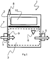
- Figure 1 schematically shows a gas meter 1 of the static type.
- the meter 1 comprises, in a known manner, a hollow body 2 defining a measuring compartment 3 provided with an inlet pipe 4 and an outlet pipe 5 for the passage of the gas (shown by the arrows in fig.1 ) that, from the pipe network, has to go to the user.
- the sensor 6 is connected to a control unit 7 that processes the measurements of the sensor, stores the measurement value and it transmits it by activating a transmitter 8.
- the control unit controls a valve 9, inside the meter, that opens or closes the gas passage from the pipe network to the user service pipe. Then the meter is provided with a LCD display 10 for an operator to read the consumption measurement.
- Figure 2 shows a block diagram of the meter 1, according to a first embodiment of the present invention.
- the meter 1 comprises a battery 11 with such a capacity to power all the electric/electronic components of the meter.
- the battery 11 is a lithium battery with a capacity of 19 Ah (type D) able to maintain at its ends a voltage of 3,6V for its entire useful life if the current required to it is limited to low and constant values.
- the battery 11 is selected so as to operate within a wide range of temperatures, preferably ranging from -25°C to +55°C, this because the meter has to be able to be installed in places with very different environmental conditions (sea and mountain) and it has to withstand considerable thermal ranges (day/night, summer/winter).
- batteries of this type are not able, without a considerable deterioration of the life intrinsic characteristics over time, to meet the requirements of instantaneous current required by the transmitter 8 (and by the inboard electronics, generally denoted by reference 12) for transmitting via radio the measurements of the meter for generally allowing utility companies to have the remote access thereto.
- a charging pack 13 is provided which is able to supply to the transmitter 8 the current it needs for the maximum established time for transmitting the amount of data defined by the specific connection.
- the charging pack 13 is replaced by a plurality of capacitors in series, and particularly a plurality of super-capacitors (known by the English term supercaps), able to store the energy sufficient for operating the transmitter 8 for the time sufficient for communicating the measurement of the gas consumption and all the data about the management of the user over time.
- super-capacitors known by the English term supercaps
- Supposing the transmitter 8 is of the GPRS type, and in order to allow a suitable communication time, in the preferred embodiment two supercaps are used which are placed in series.
- the voltage supplied from the battery 11 is supplied at the ends of the transmitter 8 and of the charging pack 13 through a voltage regulating circuit 14 controlled by the control unit 7 comprising a microcontroller.
- the regulating circuit 14 is an electronic switch (for example a transistor) that opens or closes the connection between the battery 11 and the charging pack 13.
- the control unit 7 controls the charging cycles of the charging pack 13 and it keeps the energy consumptions under control as shown in figure 3 .
- the control unit 7 is programmed for activating the transmitter and for transmitting the measurements of the sensor every t1 seconds, for example every 12 hours.
- the transmission lasts a time ⁇ 2, e.g. 30s, depending on the amount of data to be transmitted and on the response time of the network the gas meter connects to, and it requires an average energy E1.
- the control unit 7 controls the regulating circuit 14 and therefore it connects the charging pack 13 to the battery 11 at a moment t0, prior to time t1 of the beginning of the transmission.
- the time t0 is calculated by the control unit such that in the time t0-t1 ( ⁇ 1), the charging pack 13 is charged and it stores an energy higher than or equal to E1.
- the voltage control circuit 14 of figure 2 is replaced by two blocks, denoted by reference numbers 15 and 16, arranged upstream and downstream of the charging pack 13.
- the block 15 is a controlled booster, able to perform two functions: to provide an output voltage higher than the input one and to limit the output current, that is the charging current of the charging pack 13.
- the control unit 7 When the control unit 7 activates the booster, the voltage supplied by the battery (3.6V) is risen to 4.8V such that the charging pack 13 charges more quickly till storing more energy than a charging with a voltage of 3.6V, the stored energy being proportional to the square of the voltage.
- the choice of the voltage of 4.8V depends on the intrinsic parameters of the supercaps of the charging pack 13, particularly, the booster 15 is controlled by the control unit 7 so as to provide an output voltage V out equal to NV MAX , where V MAX is the maximum voltage, according to specifications, that can be withstood by the supercap without being damaged, while N is the number of supercaps arranged in series in the charging pack 13.
- the choice of 4.8V is therefore optimal for a charging pack comprising two supercaps arranged in series and able to withstand a maximum voltage of 2,4 V guaranteeing the functional profile as regards electrical characteristics and quality over time.
- the booster 15 is controlled so as to raise the output voltage gradually from a minimum value (in the example described here 3.6V) to a maximum one (in the example described here 4,8V); thus the control unit can be configured so as to raise the voltage at the ends of the charging pack 13 according to a raising curve that depends on the choice of the capacitors.
- the curve is selected such that 4.8V are kept for a relatively short time during the day (and typically only in anticipation of a scheduled transmission) so as to optimize the life of the capacitors.
- the booster 15 is preferably controlled such that the voltage at the node n2 is always higher than or equal to the operating voltage of the transmitter 8, that in the example described here is equal to 3.6 V.
- the booster 15 limits the current required by the battery, and necessary for charging the supercaps, to a value suitable for optimizing the average life thereof.
- the current is limited to a value ranging from 3 to 5 mA, more preferably equal to 4 mA.
- a reading circuit outlined by line 17, reports to the control unit 7 the voltage at node n2, thus the control unit knows at each moment the voltage at the ends of the charging pack and it stops the booster when it detects a voltage equal to 4.8V.
- the frequency of such control over time is a programmable parameter.
- the transmitter 8 operates at 3.6V (with a minimum operation limit also lower and equal to 3.2V), therefore between the charging pack 13 and the transmitter 8 there is provided a DC/DC converter (Buck converter) that restores the voltage from 4.8V to a value useful for the operation of the transmitter, for example ranging from 3.3 V to 3.6V.
- a DC/DC converter Buck converter
- control unit 7 controls the buck converter 16 by disconnecting the connection between the charging pack 13 and the transmitter 8 during the charging phases of the charging pack 13 so as to optimize them and to reduce the consumptions (and leakages) of the system.
- the control unit 7 disconnects the connection between the battery 11 and the charging pack 13 during the transmission of the consumption measurements (or each datum related thereto and stored in the memory of the electronics) by the transmitter 8 and more preferably for all the time when the charging pack 13 needs not to be charged; this is performed by controlling the booster 15.
- the control unit is programmed for transmitting the data by using the transmission module at a predetermined time moment T TR (e.g. at a specific day and time in the day); before transmitting the data the control unit disconnects the booster circuit from the battery, such that the transmission takes place by using only the energy stored in the charging pack 13.
- the use of the booster 15 and of the buck converter 16 controllable by the control unit 7, allows the charging pack 13 to be completely isolated, and the reading of the sensor to be kept stable. Should the measuring electronics and the control electronics directly be connected to the charging pack, the current peaks absorbed by the communication circuit during the transmission inevitably would cause serious voltage drops thereon disturbing or preventing them to operate. Particularly the fact of using a booster 15 that limits the current that can be required by the battery, prevents the sudden requirement of current by the transmitter 8 when it has to transmit from causing oscillations on the power supply voltage of the sensor changing the measurement in a non-predictable manner.
- the sensor 6 and the actuators 90 controlling the valve 9 are powered by a line provided with a current limiter 18 that starts from the node n3, such node being the node closest to the battery 11. That is to say, all the other devices of the meter take the power supply upstream of the sensors 6 and of the valve actuators 90.
- the limiter 18 is necessary as a protection for limiting the energy flow towards the circuit part disposed in the gas environment (the sensor 6 and the valve 9) that, due also to faults leading to a short-circuit thereof, could potentially dissipate such an energy to trigger an explosion of the gas mixture.
- valve actuators 90 are powered by the charging pack 13 and therefore they are connected thereto by a buck converter that can be controlled by the control unit such not to absorb or waste current when not in operation.
- the actuators 90 are therefore connected downstream of the buck converter 16. This choice optimizes the average life of the battery 11, since such actuators (e.g. the motor of the valve 9) can require some dozens of milliamperes and so the battery can be stressed.
- the limiter 18 is a limiter controllable through an activation input ( enable), for example the limiter 18 comprises an integrated limiting circuit of the type used in HDMI connections. This type of circuits however has some leakages ( leakage- leakage currents) that can be reduced by sending on the enable input a signal for powering off the limiter, that, actually, sets at zero the output voltage from the limiter.
- the limiter 18 comprises an integrated limiting circuit 180, of the type used in HDMI solutions, that, between the input and output pins, has a bypass resistance R with such a dimension for a current to pass which is just sufficient for maintaining the sensor in stand-by (which otherwise would be switched off and would require to be switched on at each measurement step); preferably such current is of few milliamperes, preferably 1 ⁇ A.
- control unit 7 can be configured for effectively performing discrete flow measurements over time and contemporaneously reducing at the minimum the power dissipated in the steps between one and the other measurement.
- the control unit 7 disables the limiter 18 and it goes in a standby condition reducing the energy consumptions. After a predetermined time, for example 2s, an internal clock of the control unit 7 activates it again and in turn it activates the limiter 18 allowing the sensor to quickly leave the standby condition, so it can measure the flow gas in few ⁇ s. This would not be possible without the bypass resistance that powers the sensor when this latter does not measure and is in the low absorption condition, since by completely disabling the sensor, it would take more time to awake it, and as a consequence, this would result in a higher waste of energy associated to each awakening.
- measurements are not taken regularly on the basis of a predetermined time, but they are taken by following a prediction algorithm that calculates, on the basis of the previous measurements, whether gas is currently used therefore it is better to perform measurements more frequent over time and/or measurements with a different accuracy and a consequent different energy balance.
- the control unit detects a gas flow higher than the previous measurements and so it decides that the following measurement has to be taken not after 2s but within a shorter time.
- the time interval is preferably chosen on the basis of the value of the measurement, or still better on the basis of the differential to the previous measurement.
- the senor 6 is able to perform measurements of two types: a QUICK measurement and an ACCURATE one.
- the latter is very accurate, but it requires a lot of energy, while the former is less accurate and requires less energy.
- the control unit in this case, as an alternative or in combination with the regulation of the measurement intervals, it is possible to configure the control unit such that it requires ACCURATE measurements when it verifies a (positive or negative) derivative higher than a threshold value in the consumption curve.
- a threshold value in the consumption curve This is better shown with reference to the consumption curve shown in figure 7 ; at time T0 hot water is turned on and therefore the sensor detects, every 2s, a regular consumption; therefore the control unit controls the sensor in order to perform QUICK measurements. Then, at time T1 the user turns on the fire and so the consumptions raise till settling at the final value reached at time T2. Between T1 and T2 the control unit detects an increase in the consumptions and so it performs ACCURATE measurements.
- the choice between QUICK and ACCURATE measurements depends not only on the derivative of the consumptions, but also on the historical data used for reducing to the minimum amount necessary the number of ACCURATE measurements, which have the highest energy consumption.
- gas distribution occurs not always in a constant manner, on the contrary it has a nonlinear pattern.
- the historical data can assist in understanding the periodicity of such pattern and in deciding that possible increases in the flow value measured depend on the pattern of the gas distribution and not on a real additional requirement of gas by the user; in this case the control unit will order to the sensor to perform QUICK measurements despite an increase in the consumptions detected between two successive measurements.
- Figure 8 shows a preferred embodiment of the control unit 7.
- the control unit comprises two microcontrollers, one (70) dedicated to the communication devices (e.g. transmitter 8) and one (71) dedicated to the metrology part of the gas meter (e.g. sensor 6) and the other most frequently used devices (e.g. display) and relevant to the so-called “Legally relevant" part of the metering apparatus.
- the microcontrollers 70 and 71 are made with different architectures, particularly the microcontroller 71 that controls the measuring circuit (sensor 6), as it is used more frequently, is made with an architecture optimized for the low power (e.g. 8 bit) and therefore it uses a silicon area smaller than the other microcontroller 70, e.g. a 32 bit microcontroller.
- the two microcontrollers 70 and 71 are put in communication, but the microcontroller 71 is equipped with a firmware identified by an identification code, for example a CRC code (Cyclic Redundancy Check) or digital signature.
- an identification code for example a CRC code (Cyclic Redundancy Check) or digital signature.
- the control unit is provided with a dual port RFID receiver 72 comprising a nonvolatile rewritable memory for example a flash memory, a reading and writing circuit of the memory able to allow the memory to be read and written by a microprocessor external to the receiver and connected thereto through a data line, particularly a serial data line.
- a data line particularly a serial data line.
- the RFID interface of each meter is protected by a 32bit password, such that by irradiating several meters contemporaneously with a signal provided with a specific password, only one of such meters recognizes the password as valid and it is activated by loading the data transmitted with the signal irradiated.
- the transmitted data comprise specific data of the meter (calibration coefficient of the sensor, various IDs of the meter such as serial number of the meter, serial number of the valve ecc..) and a code (sealing) that warns the meter that from now on it cannot be calibrated again anymore.
- the data received in this manner are stored into a nonvolatile memory, e.g. a flash memory, of the RFID receiver.
- the RFID receiver directly supplies, by the energy obtained from the RF radiation, a small dedicated microcontroller 73, which sends a LOCK signal to the receiver locking the mechanisms of rewriting of the nonvolatile memory.
- a small dedicated microcontroller 73 which sends a LOCK signal to the receiver locking the mechanisms of rewriting of the nonvolatile memory.
- the writing of the nonvolatile memory of the RFID receiver is locked at the first starting of the meter.
- the control unit 7 reads the data present into the memory of the RFID receiver and it sends the Lock command to the RFID receiver for preventing its memory from being re-written in the future.
- the data written in the memory of the RFID interface are encrypted in order to prevent them from being re-written during the transport phase or anyway before turning the meter on for the first time. This protection serves for covering the time between the exit of the meter from the plant to the first installation thereof.
- the gas meter is equipped with a transceiver 8 that receives and transmits data from/to a remote server, directly (GPRS connection) or by a concentration apparatus that manages several meters, and in turn it connects to the remote server through a GPRS connection.
- a transceiver 8 that receives and transmits data from/to a remote server, directly (GPRS connection) or by a concentration apparatus that manages several meters, and in turn it connects to the remote server through a GPRS connection.
- gas meters have to be installed in locations not covered by the radio network to which they have to be connected for transmitting data (e.g. a cellar), or they may be installed into a metal cabinet, that, shielding the meters, prevents them from being reached via radio.
- the meter is provided with a transmission kit composed of a passive repeater system composed of two antennas calibrated and connected by a cable.
- Figure 10 shows the meter 1 installed inside a cabinet 100 that has a metal shielding that would prevent the transmitter 8 of the meter and an access apparatus 111 of a communication network 110 from communicating.
- the passive repeater system 19 is mounted 100 by passing the cable 190 connecting the two antennas 191 and 192 through an opening (possibly made during the installation phase by drilling a hole in the cabinet 100).
- at least one of the antennas 191, 192 is fastened to the cable 190 by a removable connector, more preferably both the antennas are provided with such connector, such that, depending on applications, it is possible to use cables of various lengths, or as an alternative to the cable, other antenna connection means, such as for example rigid connectors, that allow the two antennas to be put in direct contact.
- the passive repeater system is provided with a mounting kit that comprises, for example, clamps for coupling the cable and/or the antennas to different surfaces.
- the antenna of the transmitter 8 sends radio waves that are received by the antenna 191 of the passive repeater arranged inside the cabinet 100; the radio signal is then converted into an electric signal, that, through the cable, reaches the antenna 192 arranged outside the cabinet. This latter antenna, in turn, generates a radio signal due to the signal in the cable 190.
- the data transmitted from the antenna of the meter 1 in this manner, reach the access system of the network 110 and consequently a remote server.
- the meter 1 shown in figure 11 is not provided with an autonomous antenna for the transmission.
- the passive repeater 19 comprises, instead, an antenna 193 embedded into a plastic body suitably shaped for coupling to the body of the container 1.
- Such body is provided, in addition to removable coupling means, with electrical connectors for the electrical connection of the antenna to the transceiver system (modulator, demodulator and antenna amplifier) of the meter 1.
- such antenna is integrated in the body of the meter and to provide a connector for the connection to the cable 190.
- a part of the passive repeater system is integrated to the body of the meter.
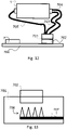
- Figure 12 shows a detail of the battery 11 and of its connection to the PCB board 700 housing the control unit 7.
- the conventional solution to be used in similar cases would provide an anti-tamper button that is activated if the cover of the battery compartment is removed with consequent mechanical complications and an increase in the costs.
- the two poles of the battery 11 are cabled to a connector 701 adapted to be fitted into a corresponding connector 702 arranged on the PCB 700.
- the cabling of the battery 11 provides two ground cables 703 and 704 connected to the negative pole and individually brought to the power supply connector 701, and only one cable 705 going from the positive pole of the battery 11 to the connector 701.
- the cable 703 is actually used for performing the ground connection function, while the cable 704 brings again (by a line not shown in the figure) the ground itself to an input of the microprocessor such that it can detects the presence of the signal relevant to the ground connection.
- This arrangement allows the removal of the battery to be detected without a microswitch intended for the purpose and therefore with a cost saving of mechanical parts.
- control unit 7 Upon the removal of the battery the system is still powered by the charging pack 13, the control unit 7 detects a voltage change at the input connected to the cable 704 causing an alarm condition. Therefore the control unit uses the energy of the charging pack 13 to power the transmitter 8 and to send an alarm signal, for example a text message such as a SMS.
- the meter is provided with a backup battery, usually not connected to the electric/electronic system, and it is able to allow the meter to operate for a specific time, for example two years.
- control unit 7 When the control unit 7 detects a power supply voltage (e.g. at the node n1) falling below a threshold value, it connects (for example by operating a switch in the closing condition) the backup battery instead of the battery 11, such that it allows all the components to operate: from the sensor to the transmitter.
- a power supply voltage e.g. at the node n1
- the backup battery instead of the battery 11, such that it allows all the components to operate: from the sensor to the transmitter.
- control unit can be arranged for transmitting an alarm signal or for displaying such signal on the display.
- the meter can be provided with two batteries, one (e.g. a D type 19A battery) intended for powering the metrological components of the meter, and a smaller one (e.g. a B or D type battery) intended for powering the components of the meter in charge of the communication.
- a D type 19A battery intended for powering the metrological components of the meter
- a smaller one e.g. a B or D type battery
- the power supply circuits of the metrological part and of the communication part are separated, therefore there are no problems as regards the measurement as described above and resulting from the oscillation of the power supply voltage of the metrological sensor when the meter communicates the data or when the charging pack 13 has to be recharged.
- FIG. 13 Due to the energy requirements of the system, in one embodiment schematically shown in figure 13 , there is implemented a system for the protection against electrostatic discharges (ESD) by designing a discharger 706 integrated on the printed circuit (PCB, 700) and by designing a preferred discharging path for the energy that in the example of figure 13 is depicted by a plurality of triangles whose upper vertex (opposite to the base) is faced towards the connector 702, and wherein the base of the triangle is connected to a ground line 707.
- ESD electrostatic discharges
- Zener diodes, Varistors, ecc) that, besides being a cost, they dissipate current.
- a triangle is provided for each pin of the connector 702.
- the discharger 706 can take different shapes, provided that there are provided tips faced towards the connector 702 so as to collect and convey electrostatic discharges, if any, to the ground.
- the fact of connecting (in any way also different from the connector of figure 12 ) a pole of the battery both to a ground line of the meter and to an alarm input of the control unit, together to the fact of configuring the control unit for sending an alarm signal through the transmission system when the voltage at the alarm input changes over a certain predetermined threshold, allows to detect in a simple and effective way possible tamperings of the battery.
- the invention is therefore directed also to a static gas meter comprising:
- a pole of the battery is connected both to a ground line of the meter, and to an alarm input of the control unit and that the control unit is configured for sending an alarm signal via the transmission system, when the voltage at the alarm input changes over a specific threshold.
- the meter further comprising an auxiliary battery and the control unit is adapted to connect said auxiliary battery to the metrological components of the meter if the voltage at the alarm input changes over a specific threshold.
- the main battery is connected to a printed circuit board, upon which the control unit is mounted, by a connector.
- the printed circuit board is further provided with a system for the protection against electrostatic discharges which comprises a discharger designed on the printed circuit board and comprises a preferential discharging path for the energy.
- the discharger comprises a plurality of discharging elements, particularly triangles, which have a vertex remotely positioned with respect to the connector and connected to a ground line of the meter.
- the discharger comprises a number of discharging elements equal to the number of pins of the connector.
Landscapes
- Physics & Mathematics (AREA)
- Fluid Mechanics (AREA)
- General Physics & Mathematics (AREA)
- Arrangements For Transmission Of Measured Signals (AREA)
- Measuring Volume Flow (AREA)
Claims (3)
- Gaszähler umfassend:- eine Steuereinheit (7),- eine Messschaltung (6) zur Erfassung eines Gasflusses,- ein drahtloses Übertragungssystem (8) zum Übertragen der von der Messschaltung vorgenommenen Messungen,- eine Batterie, die dazu eingerichtet ist, eine Versorgungsspannung zur Versorgung der Steuereinheit (7), der Messschaltung (6) und des Übertragungssystems (8) zu erzeugen,dadurch gekennzeichnet, dass das Übertragungssystem (8) einen Modulator, einen Demodulator, einen Antennenverstärker und einen passiven Repeater (19) umfasst;wobei der passive Repeater (19) eine erste Antenne (193), die in das Gehäuse des Zählers integriert ist, und eine zweite Antenne (192) umfasst, die mit der ersten Antenne über ein Kabel (190) verbunden ist, wobei das Kabel (190) mit der ersten Antenne (193) über einen Verbinder verbunden ist, wobei die erste Antenne mit elektrischen Verbindern für die Verbindung der ersten Antenne mit dem Modulator, Demodulator und Antennenverstärker versehen ist.
- Zähler nach Anspruch 1, wobei das passive Repeater-System ein Befestigungssystem, insbesondere Klemmen, zur Verbindung des passiven Repeaters mit einer Oberfläche umfasst.
- Zähler nach Anspruch 1 oder 2, wobei die Messschaltung einen elektronischen Sensor umfasst, der für eine Messung der Masseart geeignet ist.
Applications Claiming Priority (3)
| Application Number | Priority Date | Filing Date | Title |
|---|---|---|---|
| IT000628A ITMI20120628A1 (it) | 2012-04-17 | 2012-04-17 | Contatore gas statico con sistema di allarme batteria |
| IT000630A ITMI20120630A1 (it) | 2012-04-17 | 2012-04-17 | Contatore gas con ripetitore passivo |
| PCT/IB2013/053047 WO2013156947A1 (en) | 2012-04-17 | 2013-04-17 | Gas meter with passive repeater |
Publications (2)
| Publication Number | Publication Date |
|---|---|
| EP2839252A1 EP2839252A1 (de) | 2015-02-25 |
| EP2839252B1 true EP2839252B1 (de) | 2022-03-30 |
Family
ID=48628744
Family Applications (1)
| Application Number | Title | Priority Date | Filing Date |
|---|---|---|---|
| EP13729430.2A Active EP2839252B1 (de) | 2012-04-17 | 2013-04-17 | Gaszähler mit passivrepeater |
Country Status (2)
| Country | Link |
|---|---|
| EP (1) | EP2839252B1 (de) |
| WO (1) | WO2013156947A1 (de) |
Families Citing this family (5)
| Publication number | Priority date | Publication date | Assignee | Title |
|---|---|---|---|---|
| GB2519121A (en) * | 2013-10-10 | 2015-04-15 | Abb Ltd | Metering device and parts therefor |
| CN105957322A (zh) * | 2016-05-24 | 2016-09-21 | 河南师范大学 | 一种远程燃气流量计系统及其控制方法 |
| WO2018152620A1 (en) | 2017-02-24 | 2018-08-30 | Les Systemes Fonex Data Inc. | System and method for programming pluggable transceivers |
| WO2019108986A1 (en) * | 2017-11-30 | 2019-06-06 | Michael Munoz | Internet of things (iot) enabled wireless sensor system enabling process control, predictive maintenance of electrical distribution networks, liquid and gas pipelines and monitoring of air pollutants including nuclear, chemical, and biological agents using attached and/or embedded passive electromagnetic sensors |
| CA3127348A1 (en) | 2018-12-21 | 2020-06-25 | Fonex Data Systems Inc. | Systems and methods for programming pluggable transceivers |
Citations (3)
| Publication number | Priority date | Publication date | Assignee | Title |
|---|---|---|---|---|
| US5659300A (en) * | 1995-01-30 | 1997-08-19 | Innovatec Corporation | Meter for measuring volumetric consumption of a commodity |
| WO2002073735A2 (en) * | 2001-03-09 | 2002-09-19 | Arad Measuring Technologies Ltd. | Meter register and antenna |
| EP2187174A1 (de) * | 2008-11-14 | 2010-05-19 | Kamstrup A/S | Kommunikationsvorrichtung zur drahtlosen Kommunikation mit Verbrauchsmesser |
Family Cites Families (2)
| Publication number | Priority date | Publication date | Assignee | Title |
|---|---|---|---|---|
| US7337078B2 (en) * | 2004-01-16 | 2008-02-26 | Worldtelemetry, Inc. | System and method for remote asset monitoring |
| JP5663475B2 (ja) * | 2008-05-23 | 2015-02-04 | ローズマウント インコーポレイテッド | エネルギの流れの計算を備える多変数プロセス流体の流れの装置 |
-
2013
- 2013-04-17 EP EP13729430.2A patent/EP2839252B1/de active Active
- 2013-04-17 WO PCT/IB2013/053047 patent/WO2013156947A1/en not_active Ceased
Patent Citations (3)
| Publication number | Priority date | Publication date | Assignee | Title |
|---|---|---|---|---|
| US5659300A (en) * | 1995-01-30 | 1997-08-19 | Innovatec Corporation | Meter for measuring volumetric consumption of a commodity |
| WO2002073735A2 (en) * | 2001-03-09 | 2002-09-19 | Arad Measuring Technologies Ltd. | Meter register and antenna |
| EP2187174A1 (de) * | 2008-11-14 | 2010-05-19 | Kamstrup A/S | Kommunikationsvorrichtung zur drahtlosen Kommunikation mit Verbrauchsmesser |
Also Published As
| Publication number | Publication date |
|---|---|
| WO2013156947A1 (en) | 2013-10-24 |
| EP2839252A1 (de) | 2015-02-25 |
Similar Documents
| Publication | Publication Date | Title |
|---|---|---|
| EP2839250B1 (de) | Statischer gaszähler mit massnahmenübertragungssystem und zugehöriges übertragungsverfahren | |
| EP2839252B1 (de) | Gaszähler mit passivrepeater | |
| US7746246B2 (en) | Housing for utility meter AMR components | |
| US8866634B2 (en) | System and method for remotely monitoring and controlling a water meter | |
| CN102629123B (zh) | 能进行射频通信的过程现场设备 | |
| KR101528298B1 (ko) | 쓰레기 수거용 모듈 장치 및 상기 모듈 장치의 동작 방법 | |
| US20080316051A1 (en) | Mutltiple mode amr system for water meters | |
| EP3486617B1 (de) | Gaszähler mit intelligenter stromversorgung | |
| WO2013156946A1 (en) | Static gas meter with improved electronics | |
| EP3217154B1 (de) | Drahtloses automatisches verbrauchszähler | |
| CA2905142C (en) | Utility device interface | |
| US11493544B2 (en) | Electronic electricity meter | |
| ITMI20120631A1 (it) | Contatore gas statico | |
| KR102440340B1 (ko) | 외장형 전원을 구비한 원격 검침 단말기 | |
| US10073124B2 (en) | Electronic meter seal arrangement and method | |
| KR102765510B1 (ko) | 원격검침용 통신모뎀 전환 장치 및 방법 | |
| KR101680062B1 (ko) | 근거리 통신 장치, 표시장치 및 콘센트장치 | |
| AU2019325340B2 (en) | System, method, and computer program product for wake up of a water meter | |
| ITMI20120628A1 (it) | Contatore gas statico con sistema di allarme batteria | |
| ITMI20120630A1 (it) | Contatore gas con ripetitore passivo | |
| ITMI20120627A1 (it) | Contatore gas statico con sistema di trasmissione delle misure e relativo metodo di trasmissione | |
| US20240304920A1 (en) | Intrinsically-safe battery assembly for wireless field devices | |
| CN205657139U (zh) | 一种内置通讯模块的物联网电池 | |
| CN106133479B (zh) | 对受保护设备的工作的管理 | |
| US20250219440A1 (en) | Power management systems, devices, and methods |
Legal Events
| Date | Code | Title | Description |
|---|---|---|---|
| PUAI | Public reference made under article 153(3) epc to a published international application that has entered the european phase |
Free format text: ORIGINAL CODE: 0009012 |
|
| 17P | Request for examination filed |
Effective date: 20141114 |
|
| AK | Designated contracting states |
Kind code of ref document: A1 Designated state(s): AL AT BE BG CH CY CZ DE DK EE ES FI FR GB GR HR HU IE IS IT LI LT LU LV MC MK MT NL NO PL PT RO RS SE SI SK SM TR |
|
| AX | Request for extension of the european patent |
Extension state: BA ME |
|
| DAX | Request for extension of the european patent (deleted) | ||
| STAA | Information on the status of an ep patent application or granted ep patent |
Free format text: STATUS: EXAMINATION IS IN PROGRESS |
|
| 17Q | First examination report despatched |
Effective date: 20191023 |
|
| REG | Reference to a national code |
Ref country code: DE Ref legal event code: R079 Ref document number: 602013081248 Country of ref document: DE Free format text: PREVIOUS MAIN CLASS: G01F0015060000 Ipc: G01F0015000000 |
|
| GRAP | Despatch of communication of intention to grant a patent |
Free format text: ORIGINAL CODE: EPIDOSNIGR1 |
|
| STAA | Information on the status of an ep patent application or granted ep patent |
Free format text: STATUS: GRANT OF PATENT IS INTENDED |
|
| RIC1 | Information provided on ipc code assigned before grant |
Ipc: G01F 15/06 20060101ALI20211201BHEP Ipc: G01F 15/00 20060101AFI20211201BHEP |
|
| INTG | Intention to grant announced |
Effective date: 20220105 |
|
| GRAS | Grant fee paid |
Free format text: ORIGINAL CODE: EPIDOSNIGR3 |
|
| GRAA | (expected) grant |
Free format text: ORIGINAL CODE: 0009210 |
|
| STAA | Information on the status of an ep patent application or granted ep patent |
Free format text: STATUS: THE PATENT HAS BEEN GRANTED |
|
| AK | Designated contracting states |
Kind code of ref document: B1 Designated state(s): AL AT BE BG CH CY CZ DE DK EE ES FI FR GB GR HR HU IE IS IT LI LT LU LV MC MK MT NL NO PL PT RO RS SE SI SK SM TR |
|
| REG | Reference to a national code |
Ref country code: GB Ref legal event code: FG4D |
|
| REG | Reference to a national code |
Ref country code: CH Ref legal event code: EP |
|
| REG | Reference to a national code |
Ref country code: DE Ref legal event code: R096 Ref document number: 602013081248 Country of ref document: DE |
|
| REG | Reference to a national code |
Ref country code: AT Ref legal event code: REF Ref document number: 1479607 Country of ref document: AT Kind code of ref document: T Effective date: 20220415 |
|
| REG | Reference to a national code |
Ref country code: IE Ref legal event code: FG4D |
|
| REG | Reference to a national code |
Ref country code: NL Ref legal event code: FP |
|
| REG | Reference to a national code |
Ref country code: LT Ref legal event code: MG9D |
|
| PG25 | Lapsed in a contracting state [announced via postgrant information from national office to epo] |
Ref country code: SE Free format text: LAPSE BECAUSE OF FAILURE TO SUBMIT A TRANSLATION OF THE DESCRIPTION OR TO PAY THE FEE WITHIN THE PRESCRIBED TIME-LIMIT Effective date: 20220330 Ref country code: RS Free format text: LAPSE BECAUSE OF FAILURE TO SUBMIT A TRANSLATION OF THE DESCRIPTION OR TO PAY THE FEE WITHIN THE PRESCRIBED TIME-LIMIT Effective date: 20220330 Ref country code: NO Free format text: LAPSE BECAUSE OF FAILURE TO SUBMIT A TRANSLATION OF THE DESCRIPTION OR TO PAY THE FEE WITHIN THE PRESCRIBED TIME-LIMIT Effective date: 20220630 Ref country code: LT Free format text: LAPSE BECAUSE OF FAILURE TO SUBMIT A TRANSLATION OF THE DESCRIPTION OR TO PAY THE FEE WITHIN THE PRESCRIBED TIME-LIMIT Effective date: 20220330 Ref country code: HR Free format text: LAPSE BECAUSE OF FAILURE TO SUBMIT A TRANSLATION OF THE DESCRIPTION OR TO PAY THE FEE WITHIN THE PRESCRIBED TIME-LIMIT Effective date: 20220330 Ref country code: BG Free format text: LAPSE BECAUSE OF FAILURE TO SUBMIT A TRANSLATION OF THE DESCRIPTION OR TO PAY THE FEE WITHIN THE PRESCRIBED TIME-LIMIT Effective date: 20220630 |
|
| REG | Reference to a national code |
Ref country code: AT Ref legal event code: MK05 Ref document number: 1479607 Country of ref document: AT Kind code of ref document: T Effective date: 20220330 |
|
| PG25 | Lapsed in a contracting state [announced via postgrant information from national office to epo] |
Ref country code: LV Free format text: LAPSE BECAUSE OF FAILURE TO SUBMIT A TRANSLATION OF THE DESCRIPTION OR TO PAY THE FEE WITHIN THE PRESCRIBED TIME-LIMIT Effective date: 20220330 Ref country code: GR Free format text: LAPSE BECAUSE OF FAILURE TO SUBMIT A TRANSLATION OF THE DESCRIPTION OR TO PAY THE FEE WITHIN THE PRESCRIBED TIME-LIMIT Effective date: 20220701 Ref country code: FI Free format text: LAPSE BECAUSE OF FAILURE TO SUBMIT A TRANSLATION OF THE DESCRIPTION OR TO PAY THE FEE WITHIN THE PRESCRIBED TIME-LIMIT Effective date: 20220330 |
|
| PG25 | Lapsed in a contracting state [announced via postgrant information from national office to epo] |
Ref country code: SM Free format text: LAPSE BECAUSE OF FAILURE TO SUBMIT A TRANSLATION OF THE DESCRIPTION OR TO PAY THE FEE WITHIN THE PRESCRIBED TIME-LIMIT Effective date: 20220330 Ref country code: SK Free format text: LAPSE BECAUSE OF FAILURE TO SUBMIT A TRANSLATION OF THE DESCRIPTION OR TO PAY THE FEE WITHIN THE PRESCRIBED TIME-LIMIT Effective date: 20220330 Ref country code: RO Free format text: LAPSE BECAUSE OF FAILURE TO SUBMIT A TRANSLATION OF THE DESCRIPTION OR TO PAY THE FEE WITHIN THE PRESCRIBED TIME-LIMIT Effective date: 20220330 Ref country code: PT Free format text: LAPSE BECAUSE OF FAILURE TO SUBMIT A TRANSLATION OF THE DESCRIPTION OR TO PAY THE FEE WITHIN THE PRESCRIBED TIME-LIMIT Effective date: 20220801 Ref country code: ES Free format text: LAPSE BECAUSE OF FAILURE TO SUBMIT A TRANSLATION OF THE DESCRIPTION OR TO PAY THE FEE WITHIN THE PRESCRIBED TIME-LIMIT Effective date: 20220330 Ref country code: EE Free format text: LAPSE BECAUSE OF FAILURE TO SUBMIT A TRANSLATION OF THE DESCRIPTION OR TO PAY THE FEE WITHIN THE PRESCRIBED TIME-LIMIT Effective date: 20220330 Ref country code: CZ Free format text: LAPSE BECAUSE OF FAILURE TO SUBMIT A TRANSLATION OF THE DESCRIPTION OR TO PAY THE FEE WITHIN THE PRESCRIBED TIME-LIMIT Effective date: 20220330 Ref country code: AT Free format text: LAPSE BECAUSE OF FAILURE TO SUBMIT A TRANSLATION OF THE DESCRIPTION OR TO PAY THE FEE WITHIN THE PRESCRIBED TIME-LIMIT Effective date: 20220330 |
|
| REG | Reference to a national code |
Ref country code: DE Ref legal event code: R119 Ref document number: 602013081248 Country of ref document: DE |
|
| PG25 | Lapsed in a contracting state [announced via postgrant information from national office to epo] |
Ref country code: PL Free format text: LAPSE BECAUSE OF FAILURE TO SUBMIT A TRANSLATION OF THE DESCRIPTION OR TO PAY THE FEE WITHIN THE PRESCRIBED TIME-LIMIT Effective date: 20220330 Ref country code: IS Free format text: LAPSE BECAUSE OF FAILURE TO SUBMIT A TRANSLATION OF THE DESCRIPTION OR TO PAY THE FEE WITHIN THE PRESCRIBED TIME-LIMIT Effective date: 20220730 Ref country code: AL Free format text: LAPSE BECAUSE OF FAILURE TO SUBMIT A TRANSLATION OF THE DESCRIPTION OR TO PAY THE FEE WITHIN THE PRESCRIBED TIME-LIMIT Effective date: 20220330 |
|
| REG | Reference to a national code |
Ref country code: CH Ref legal event code: PL |
|
| REG | Reference to a national code |
Ref country code: BE Ref legal event code: MM Effective date: 20220430 |
|
| PG25 | Lapsed in a contracting state [announced via postgrant information from national office to epo] |
Ref country code: MC Free format text: LAPSE BECAUSE OF FAILURE TO SUBMIT A TRANSLATION OF THE DESCRIPTION OR TO PAY THE FEE WITHIN THE PRESCRIBED TIME-LIMIT Effective date: 20220330 Ref country code: LU Free format text: LAPSE BECAUSE OF NON-PAYMENT OF DUE FEES Effective date: 20220417 Ref country code: LI Free format text: LAPSE BECAUSE OF NON-PAYMENT OF DUE FEES Effective date: 20220430 Ref country code: DK Free format text: LAPSE BECAUSE OF FAILURE TO SUBMIT A TRANSLATION OF THE DESCRIPTION OR TO PAY THE FEE WITHIN THE PRESCRIBED TIME-LIMIT Effective date: 20220330 Ref country code: DE Free format text: LAPSE BECAUSE OF NON-PAYMENT OF DUE FEES Effective date: 20221103 Ref country code: CH Free format text: LAPSE BECAUSE OF NON-PAYMENT OF DUE FEES Effective date: 20220430 |
|
| PLBE | No opposition filed within time limit |
Free format text: ORIGINAL CODE: 0009261 |
|
| STAA | Information on the status of an ep patent application or granted ep patent |
Free format text: STATUS: NO OPPOSITION FILED WITHIN TIME LIMIT |
|
| PG25 | Lapsed in a contracting state [announced via postgrant information from national office to epo] |
Ref country code: BE Free format text: LAPSE BECAUSE OF NON-PAYMENT OF DUE FEES Effective date: 20220430 |
|
| 26N | No opposition filed |
Effective date: 20230103 |
|
| PG25 | Lapsed in a contracting state [announced via postgrant information from national office to epo] |
Ref country code: IE Free format text: LAPSE BECAUSE OF NON-PAYMENT OF DUE FEES Effective date: 20220417 Ref country code: FR Free format text: LAPSE BECAUSE OF NON-PAYMENT OF DUE FEES Effective date: 20220530 |
|
| PG25 | Lapsed in a contracting state [announced via postgrant information from national office to epo] |
Ref country code: SI Free format text: LAPSE BECAUSE OF FAILURE TO SUBMIT A TRANSLATION OF THE DESCRIPTION OR TO PAY THE FEE WITHIN THE PRESCRIBED TIME-LIMIT Effective date: 20220330 |
|
| P01 | Opt-out of the competence of the unified patent court (upc) registered |
Effective date: 20230517 |
|
| PG25 | Lapsed in a contracting state [announced via postgrant information from national office to epo] |
Ref country code: HU Free format text: LAPSE BECAUSE OF FAILURE TO SUBMIT A TRANSLATION OF THE DESCRIPTION OR TO PAY THE FEE WITHIN THE PRESCRIBED TIME-LIMIT; INVALID AB INITIO Effective date: 20130417 |
|
| PG25 | Lapsed in a contracting state [announced via postgrant information from national office to epo] |
Ref country code: MK Free format text: LAPSE BECAUSE OF FAILURE TO SUBMIT A TRANSLATION OF THE DESCRIPTION OR TO PAY THE FEE WITHIN THE PRESCRIBED TIME-LIMIT Effective date: 20220330 Ref country code: CY Free format text: LAPSE BECAUSE OF FAILURE TO SUBMIT A TRANSLATION OF THE DESCRIPTION OR TO PAY THE FEE WITHIN THE PRESCRIBED TIME-LIMIT Effective date: 20220330 |
|
| PG25 | Lapsed in a contracting state [announced via postgrant information from national office to epo] |
Ref country code: TR Free format text: LAPSE BECAUSE OF FAILURE TO SUBMIT A TRANSLATION OF THE DESCRIPTION OR TO PAY THE FEE WITHIN THE PRESCRIBED TIME-LIMIT Effective date: 20220330 |
|
| PG25 | Lapsed in a contracting state [announced via postgrant information from national office to epo] |
Ref country code: MT Free format text: LAPSE BECAUSE OF FAILURE TO SUBMIT A TRANSLATION OF THE DESCRIPTION OR TO PAY THE FEE WITHIN THE PRESCRIBED TIME-LIMIT Effective date: 20220330 |
|
| PGFP | Annual fee paid to national office [announced via postgrant information from national office to epo] |
Ref country code: NL Payment date: 20250426 Year of fee payment: 13 |
|
| PGFP | Annual fee paid to national office [announced via postgrant information from national office to epo] |
Ref country code: GB Payment date: 20250426 Year of fee payment: 13 |
|
| PGFP | Annual fee paid to national office [announced via postgrant information from national office to epo] |
Ref country code: IT Payment date: 20250428 Year of fee payment: 13 |