EP2839617B1 - Procédés et dispositifs pour la transmission de signaux dans un système de télécommunication - Google Patents
Procédés et dispositifs pour la transmission de signaux dans un système de télécommunication Download PDFInfo
- Publication number
- EP2839617B1 EP2839617B1 EP12874625.2A EP12874625A EP2839617B1 EP 2839617 B1 EP2839617 B1 EP 2839617B1 EP 12874625 A EP12874625 A EP 12874625A EP 2839617 B1 EP2839617 B1 EP 2839617B1
- Authority
- EP
- European Patent Office
- Prior art keywords
- user
- blocks
- slot
- block
- transmitter
- Prior art date
- Legal status (The legal status is an assumption and is not a legal conclusion. Google has not performed a legal analysis and makes no representation as to the accuracy of the status listed.)
- Active
Links
Images






Classifications
-
- H—ELECTRICITY
- H04—ELECTRIC COMMUNICATION TECHNIQUE
- H04L—TRANSMISSION OF DIGITAL INFORMATION, e.g. TELEGRAPHIC COMMUNICATION
- H04L27/00—Modulated-carrier systems
- H04L27/26—Systems using multi-frequency codes
- H04L27/2601—Multicarrier modulation systems
- H04L27/2647—Arrangements specific to the receiver only
- H04L27/2649—Demodulators
- H04L27/26524—Fast Fourier transform [FFT] or discrete Fourier transform [DFT] demodulators in combination with other circuits for demodulation
-
- H—ELECTRICITY
- H04—ELECTRIC COMMUNICATION TECHNIQUE
- H04L—TRANSMISSION OF DIGITAL INFORMATION, e.g. TELEGRAPHIC COMMUNICATION
- H04L1/00—Arrangements for detecting or preventing errors in the information received
- H04L1/004—Arrangements for detecting or preventing errors in the information received by using forward error control
- H04L1/0056—Systems characterized by the type of code used
- H04L1/0057—Block codes
-
- H—ELECTRICITY
- H04—ELECTRIC COMMUNICATION TECHNIQUE
- H04J—MULTIPLEX COMMUNICATION
- H04J11/00—Orthogonal multiplex systems, e.g. using WALSH codes
-
- H—ELECTRICITY
- H04—ELECTRIC COMMUNICATION TECHNIQUE
- H04L—TRANSMISSION OF DIGITAL INFORMATION, e.g. TELEGRAPHIC COMMUNICATION
- H04L1/00—Arrangements for detecting or preventing errors in the information received
- H04L1/0001—Systems modifying transmission characteristics according to link quality, e.g. power backoff
-
- H—ELECTRICITY
- H04—ELECTRIC COMMUNICATION TECHNIQUE
- H04L—TRANSMISSION OF DIGITAL INFORMATION, e.g. TELEGRAPHIC COMMUNICATION
- H04L1/00—Arrangements for detecting or preventing errors in the information received
- H04L1/004—Arrangements for detecting or preventing errors in the information received by using forward error control
- H04L1/0041—Arrangements at the transmitter end
-
- H—ELECTRICITY
- H04—ELECTRIC COMMUNICATION TECHNIQUE
- H04L—TRANSMISSION OF DIGITAL INFORMATION, e.g. TELEGRAPHIC COMMUNICATION
- H04L27/00—Modulated-carrier systems
- H04L27/26—Systems using multi-frequency codes
- H04L27/2601—Multicarrier modulation systems
- H04L27/2602—Signal structure
-
- H—ELECTRICITY
- H04—ELECTRIC COMMUNICATION TECHNIQUE
- H04L—TRANSMISSION OF DIGITAL INFORMATION, e.g. TELEGRAPHIC COMMUNICATION
- H04L27/00—Modulated-carrier systems
- H04L27/26—Systems using multi-frequency codes
- H04L27/2601—Multicarrier modulation systems
- H04L27/2602—Signal structure
- H04L27/26035—Maintenance of orthogonality, e.g. for signals exchanged between cells or users, or by using covering codes or sequences
-
- H—ELECTRICITY
- H04—ELECTRIC COMMUNICATION TECHNIQUE
- H04L—TRANSMISSION OF DIGITAL INFORMATION, e.g. TELEGRAPHIC COMMUNICATION
- H04L27/00—Modulated-carrier systems
- H04L27/26—Systems using multi-frequency codes
- H04L27/2601—Multicarrier modulation systems
- H04L27/2626—Arrangements specific to the transmitter only
- H04L27/2627—Modulators
- H04L27/2634—Inverse fast Fourier transform [IFFT] or inverse discrete Fourier transform [IDFT] modulators in combination with other circuits for modulation
-
- H—ELECTRICITY
- H04—ELECTRIC COMMUNICATION TECHNIQUE
- H04W—WIRELESS COMMUNICATION NETWORKS
- H04W72/00—Local resource management
- H04W72/04—Wireless resource allocation
- H04W72/044—Wireless resource allocation based on the type of the allocated resource
- H04W72/0446—Resources in time domain, e.g. slots or frames
-
- H—ELECTRICITY
- H04—ELECTRIC COMMUNICATION TECHNIQUE
- H04J—MULTIPLEX COMMUNICATION
- H04J13/00—Code division multiplex systems
- H04J13/0007—Code type
- H04J13/004—Orthogonal
- H04J13/0048—Walsh
-
- H—ELECTRICITY
- H04—ELECTRIC COMMUNICATION TECHNIQUE
- H04L—TRANSMISSION OF DIGITAL INFORMATION, e.g. TELEGRAPHIC COMMUNICATION
- H04L1/00—Arrangements for detecting or preventing errors in the information received
- H04L1/08—Arrangements for detecting or preventing errors in the information received by repeating transmission, e.g. Verdan system
-
- H—ELECTRICITY
- H04—ELECTRIC COMMUNICATION TECHNIQUE
- H04L—TRANSMISSION OF DIGITAL INFORMATION, e.g. TELEGRAPHIC COMMUNICATION
- H04L27/00—Modulated-carrier systems
- H04L27/18—Phase-modulated carrier systems, i.e. using phase-shift keying
- H04L27/20—Modulator circuits; Transmitter circuits
- H04L27/2003—Modulator circuits; Transmitter circuits for continuous phase modulation
-
- H—ELECTRICITY
- H04—ELECTRIC COMMUNICATION TECHNIQUE
- H04L—TRANSMISSION OF DIGITAL INFORMATION, e.g. TELEGRAPHIC COMMUNICATION
- H04L27/00—Modulated-carrier systems
- H04L27/18—Phase-modulated carrier systems, i.e. using phase-shift keying
- H04L27/20—Modulator circuits; Transmitter circuits
- H04L27/2003—Modulator circuits; Transmitter circuits for continuous phase modulation
- H04L27/2007—Modulator circuits; Transmitter circuits for continuous phase modulation in which the phase change within each symbol period is constrained
- H04L27/2017—Modulator circuits; Transmitter circuits for continuous phase modulation in which the phase change within each symbol period is constrained in which the phase changes are non-linear, e.g. generalized and Gaussian minimum shift keying, tamed frequency modulation
Definitions
- the present invention relates to methods and devices for transmission of signals in a telecommunication system.
- a fast feedback channel for Voice over IP is proposed, see GERAN#44 GP-091988 "Fast Feedback Channel” (v1).
- IP Voice over internet protocol
- VAMOS Voice services over Adaptive Multi-user channels on One Slot
- VAMOS is a standardized 3GPP/GSM feature.
- the receiver requires complex multi-user detection since the two user signals are ordinary Gaussian minimum shift keying (GMSK) co-channel interferers.
- GMSK Gaussian minimum shift keying
- US 6,215,762 B1 discuss a spread spectrum communication system for transmitting information signals overlapping in time.
- the information signals is orthogonally encoded prior to transmission.
- the orthogonally encoded information signals comprises successively repeated blocks of information symbols having a modification factor applied to each repeated block to form mutually orthogonal coding sequences. Due to the scarcity of the electromagnetic spectrum, it is desirable to multiplex more than 2 users into a single time slot, while keeping the receiver complexity low. Moreover, it is desirable to allow the users to employ GMSK modulation. This nonlinear modulation technique has very good spectral properties and it is well suited for energy efficient analog RF front ends. Energy efficiency is always important in mobile stations.
- Multi-user multiplexing has been standardized in GSM.
- the users transmit using GMSK modulation, and become ordinary co-channel interferers.
- the downlink AQPSK modulation is used, see 3GPP TS 45.004 v9.1.0. Note that neither the uplink nor the downlink transmission modes in VAMOS create truly orthogonal subchannels.
- VAMOS Voice over IP Multimedia Subsystem
- PCT/SE2010/051082 relies on the fact that a linear modulator is used.
- user specific symbol rotation is introduced in order to generate truly orthogonal sub-channels. This idea can not be applied to GMSK or other non-linear continuous phase modulation techniques.
- transmitter and receiver technologies that allow more than two users to share the same time slot by creating orthogonal sub-channels, while keeping the receiver complexity low are provided.
- the users can in accordance with some embodiments employ GMSK or other non-linear continuous phase modulation technique.
- the transmitted signals employ some non-linear continuous phase modulation (CPM) such as GMSK.
- CPM continuous phase modulation
- GMSK GMSK
- Several users can be multiplexed into the same time slot.
- the transmission and reception methods create truly orthogonal sub-channels.
- the data for each user can be perfectly separated with a single antenna receiver.
- a method of transmitting signal with orthogonality that is appropriate for GMSK signals or other non-linear CPM signals is described.
- the method is based on block repetition, followed by a block-wise application of a technique based on the Hadamard transform.
- the Hadamard transform is usually applied to real or complex numbers, but can here serve as a tool for transforming blocks of bits. This procedure creates signals that are orthogonal.
- the received signal is split into blocks.
- the blocks are stacked into a block column vector, and a Hadamard transform is applied block-wise to the vector. This procedure decouples the users, and each user can be demodulated independently of the others, using an ordinary GMSK demodulator.
- a method of modulating a signal to be transmitted from a transmitter where the transmitted signal is transmitted in a slot with multiple N u users, with N u ⁇ 2 m , where 2 m is channel multiplexing order.
- the method is mainly characterized in that it comprises, for user k, the steps of obtaining user specific payload bits in 2 n k blocks and a rate 2 n k /2 m by which the transmitter is to transmit in the slot, where 0 ⁇ n k ⁇ m, and repeating the blocks to form a combined block, where the blocks are repeated a number of times equal to the inverse of the rate with which the transmitter transmits in the slot.
- the bits in each repeated block are then left intact or are flipped.
- the blocks that are flipped are selected according to sign of entries of a row of a 2 m *2 m Hadamard matrix.
- the selected row is user specific among the multiple users of the slot, and the method further comprises burst formatting and modulating the combined block of payload bits using a non-linear continuous phase modulation.
- the number of columns of the Hadamard matrix is at least the inverse of the rate with which the transmitter transmits in the slot.
- the combined block is divided into two equal block halves.
- a cyclic prefix is added to each of the two block halves of equal length.
- the burst is formatted in accordance with a GSM burst format. In accordance with one embodiment the burst is modulated using a GMSK modulator.
- the modulated signal is transmitted from a mobile station.
- the bandwidth in the slot is divided unequally between the users in the slot.
- the bandwidth in the slot is divided equally between the users in the slot.
- a method of receiving a modulated signal from a user equipment transmitting a signal is provided in a slot with multiple N u users, with N u ⁇ 2 m , where 2 m is channel multiplexing order.
- the method is mainly characterized by comprising, for user k, the steps of obtaining user specific payload bits in 2 n k blocks and a rate 2 n k /2 m used by the user equipment for transmitting the signal in the slot, where 0 ⁇ n k ⁇ m, wherein the transmit signal conveys a combined block of payload bits generated by the user equipment by repeating the blocks of bits a number of times equal to the inverse of the rate of transmission by the user equipment, obtaining a 2 m *2 m row of a Hadamard matrix used by the user, wherein the selected row is user specific among the multiple users of the slot, determining the synchronization position, partitioning the received signal into blocks of equal length, where the number of blocks corresponds to the inverse of the rate of the user, unflipping the samples in each partitioned block such that all blocks flipped at a transmitter are multiplied by -1, form a result block by adding elementwise the entries in all the partitioned blocks, and demodulating the result block.
- the invention also extends to receivers and transmitters arranged to perform the methods as described herein.
- the receivers and transmitters can be provided with a controller/controller circuitry for performing the above methods.
- the controller(s) can be implemented using suitable hardware and or software.
- the hardware can comprise one or many processors that can be arranged to execute software stored in a readable storage media.
- the processor(s) can be implemented by a single dedicated processor, by a single shared processor, or by a plurality of individual processors, some of which may be shared or distributed.
- a processor may include, without limitation, digital signal processor (DSP) hardware, ASIC hardware, read only memory (ROM), random access memory (RAM), and/or other storage media.
- DSP digital signal processor
- ASIC application specific integrated circuitry
- ROM read only memory
- RAM random access memory
- a transmitter adapted to modulate a signal where the signal is transmitted in a slot with multiple N u users, with N u ⁇ 2 m , where 2 m is channel multiplexing order.
- the transmitter is mainly characterized in that, the transmitter comprises, for user k, controller circuitry for obtaining user specific payload bits in 2 n k blocks and a rate 2 n k /2 m by which the transmitter is to transmit in the slot, where 0 ⁇ n k ⁇ m, the transmitter further comprising controller circuitry for repeating the blocks to form a combined block, where the blocks are repeated a number of times equal to the inverse of the rate with which the transmitter transmits in the slot and where the bits in each repeated block are then left intact or are flipped, wherein the blocks that are flipped are selected according to sign of entries of a row of a 2 m *2 m Hadamard matrix, and wherein the selected row is user specific among the multiple users of the slot, and burst formatting and modulating the combined
- the number of columns of the Hadamard matrix is at least the inverse of the rate with which the transmitter is adapted to transmit in the slot.
- the transmitter further comprises dividing the combined block into two equal block halves.
- a receiver for receiving a modulated signal from a user equipment transmitting a signal is provided in a slot with multiple N u users, with N u ⁇ 2 m , where 2 m is channel multiplexing order.
- the receiver is mainly characterized in that the receiver comprises, for user k, controller circuitry for obtaining user specific payload bits in 2 n k blocks and a rate 2 n k /2 m used by the user equipment for transmitting the signal in the slot, where 0 ⁇ n k ⁇ m, wherein the transmit signal conveys a combined block of payload bits generated by the user equipment by repeating the blocks of bits a number of times equal to the inverse of the rate of transmission by the user equipment, obtaining a 2 m *2 m row of a Hadamard matrix used by the user, wherein the selected row is user specific among the multiple users of the slot, determining the synchronization position, partitioning the received signal into blocks of equal length, where the number of blocks corresponds to the inverse of the rate
- a burst is a period of Radio Frequency (RF) carrier which is modulated by a data stream.
- RF Radio Frequency
- Tail bits are modulating bits with predefined states, known to both the receiver and the transmitter. They are appended at the beginning and end of a burst. Tail bits need not be user specific.
- Training sequence bits are modulating bits with predefined states, known to both the receiver and the transmitter. They are typically inserted as a midamble in a burst. Training sequence bits are user specific.
- Payload bits are bits obtained from the information data stream that each user needs to transmit, after channel coding (channel coding includes interleaving and possibly puncturing) and (optionally) encryption.
- the payload bits may also include bits used for in-band signaling, such as stealing flags.
- the payload bits are user specific and are unknown at the receiver side.
- Cyclic prefix bits are payload bits that are copied from the end of a block of payload bits and appended at the beginning of said block.
- a burst can contain more than one cyclic prefix, since it is sometimes advantageous to divide the payload data into several sub-blocks and append a cyclic prefix to each sub-block.
- H n ⁇ H n 2 n ⁇ I, where I denotes the identity matrix.
- the entry in the k -th row and m -th column of the Hadamard matrix shall be denoted Hn ( k,m ), 1 ⁇ k,m ⁇ 2 n .
- r ⁇ 1 ⁇ + 1 • b ⁇ , + 1 • b ⁇ ⁇
- r ⁇ 2 ⁇ + 1 • b ⁇ , ⁇ 1 • b ⁇ ⁇ .
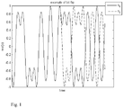
- bit flipping induces a relative phase shift of ⁇ radians between the two signals, as illustrated in Fig. 1 .
- Fig. 1 the effect of bit flip on baseband signals is shown. Only the real part shown. Ignoring border effects, the superposition of the two halves of the first signal give an amplification of the first signal, while the superposition of the two halves of the second signal cancels completely the second signal. Similarly, the difference of the two halves of the first signal cancels out the first signal, while the difference of the two halves of the second signal amplifies the second signal.
- bit flipping is tailored to the GMSK modulator with differential encoding. Had a GMSK modulation without differential encoding been used then a different definition had been stated.
- ⁇ denotes the Kronecker product
- 1 M ⁇ N is a matrix of ones of size M ⁇ N
- Matlab shorthand A ( k ,:) or A ( k , m : n ) to denote a row or a slice of a row of the matrix A .
- transmitters described below are only exemplary. Hence some of the steps performed by the transmitters may be optional in other transmitter examples without explicitly being designated as optional. The same applies to the receivers described herein.
- Let b k be the vector of N payload bits for user 1 ⁇ k ⁇ 2 m , t ⁇ left k , t ⁇ right k be the vectors of left and right tail bits, and s k be the vector of training sequence bits.
- the formatted burst for user k consists of tail bits, training sequence bits and 2 m repetitions of the block of payload bits b k , each block being modified by bit flip according to the sign of the entries in the k -th row of the Hadamard matrix.
- ⁇ 0 k is a random phase that is constant during the duration of one burst.
- the first step in the GMSK modulator is to perform differential encoding of the transmitted bits r k .
- the multiplication operation • would have to be re-defined in order to obtain the desired orthogonality properties among the transmitted signals.
- the payload bits for each user can be stacked into a matrix which can be expressed succinctly in terms of block repetition (given by the Kronecker product below) times (using the generalized Hadamard product) the Hadamard transform matrix.
- the users can have different transmitters and be located in physically separated places. So the transmitter algorithm can be thought of as a distributed application of the generalized Hadamard transform using the generalized Hadamard product.
- a simplification of the receiver processing can be achieved by adding a cyclic prefix at beginning of each half burst.
- L ⁇ 0 be the length of the cyclic prefix. It is a design parameter. A value around 4, 5 or 6 can be appropriate for GSM. For simplicity we shall restrict our to the case of 4 users. Two users do not require cyclic prefix.
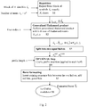
- FIG. 2 shows the transmitter processing for one user. Each user performs similar processing.
- a flow chart depicting processing in a transmitter for user number k , 1 ⁇ k ⁇ N u is shown.
- the transmitter receives as input the user specific payload bits and the total number N u of users.
- the input is the block of repeated bits as output from step S1 and the index of the user.
- the user index can for example be a unique integer that identifies the user. For example if there are 4 users the user indices are in accordance with one embodiment 1, 2, 3 and 4. According to the user index, a row of a Hadamard matrix is chosen. Each user will choose a different row. Each entry in the row is either one or minus one. There are as many entries in the row as there are repeated blocks. The bits in each block will be left intact or will be flipped according to the sign of the corresponding entry. For example if the third entry in the row is a one, then the third block is left unchanged.
- step S2 is a modification of the input block by flipping some sub-blocks according to a row of a Hadamard matrix.
- step S3 the input is the output from step S2 (i.e. the repeated, flipped, payload bits for the user) and the output is the input blocks for a user divided into two block halves of equal length. This can be useful when inserting a training sequence in the middle.
- a cyclic prefix is added to each of the two halves. This step S4 is optional.
- burst formatting is performed.
- Guard, tail and training bits are inserted, and placed in a predefined order together with the two halves of the payload bits.
- a GMSK normal burst is formatted as follows see also 3GPP TS 45.002 v9.5.0. Guard bits are added at the beginning, followed by tail bits, followed by the first half of the payload, then training sequence bits are added, followed by the second half of the payload bits. Finally more tail bits and guard bits are added.
- a modulator in particular a GMSK modulator, such as the modulator described in 3GPP TS 45.004 v9.1.0.
- r(n) denote the received signal.
- ⁇ k ( n ) ⁇ 1 - 2 b k ( n ) denote the payload symbols for user k , and let n 0 be the start of the payload symbols.
- N t be the number of training bits.
- N t be the number of training bits.
- This application of the Hadamard transform has completely separated the users.
- Y ( k ) [ y k ( 1 ), ⁇ , y k ( N )] the following expression is valid.
- ⁇ k i ⁇ k N ⁇ i , i ⁇ 0
- the noise term is independent, identically distributed v k n ⁇ N 0 ⁇ w 2 2 m .
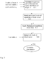
- Fig. 3 illustrates some steps performed in an exemplary receiver when processing a received signal.
- the received signal can for example be generated using a transmitter as described herein.
- a cyclic prefix is used at the transmitter side.
- the receiver is a single antenna receiver. This is typically the most challenging case for multi-user reception, and generalizations to more antenna branches are straightforward.
- the signals are received for user k , 1 ⁇ k ⁇ N u .
- step S11 the input is a received digital signal, the total number of users and a hypothesized synchronization position.
- the received signal is split into partitioned time blocks of equal length. There are as many blocks as there are users.
- a step S12 the partitioned signal is stacked to form a block vector, typically a column block vector.
- Unflipping is the opposite of flipping.
- a Hadamard transform is applied block-wise to the block vector of received samples. This means that the entries of the input block vector are multiplied by one or minus one (multiplication of vector and scalar is performed as usual, all entries of the vector are multiplied by the scalar, in this case either one or minus one.).
- the samples of a partitioned block all blocks flipped at the transmitter are multiplied by -1.
- the output is a block vector of the same dimensions as the input vector.
- one entry of the block vector is chosen according to the user index. This entry is itself a vector and contains only energy from the chosen user, while the energy from all other users has been cancelled.
- step S15 the block of samples containing only energy from one user is sent to an ordinary modulator.
- the modulator will be a GMSK demodulator.
- R [ R 1 ,..., R 2 m ] T in a slightly different form.
- R 1 r n 0 + L : n 0 + N ⁇ 1
- R 2 r n 0 + N + L : n 0 + 2 N ⁇ 1
- ⁇ R 2 m ⁇ 1 r n 0 + 2 m ⁇ 1 ⁇ 1 N + L : n 0 + 2 m ⁇ 1 N ⁇ 1
- R 2 m ⁇ 1 + 1 r n 0 + N t + 2 m ⁇ 1 N + L : n 0 + N t + 2 m ⁇ 1 N + N ⁇ 1
- R 2 m r n 0 + N t + 2 m ⁇ 1 N + L : n 0 + N t + 2 m ⁇ 1 N + N ⁇ 1
- ⁇ R 2 m r n 0 + N t + 2 m ⁇ 1 N + L : n
- Fig. 4 illustrates some steps performed in an exemplary receiver when processing a received signal not having a cyclic prefix.
- the signals are received for user k , 1 ⁇ k ⁇ N u .
- Fig. 4 the receiver side processing for one user, in case a cyclic prefix is not used at the transmitter is illustrated.
- the exemplary processing in Fig. 4 assumes a single antenna receiver. This is typically the most challenging case for multi-user reception, and generalizations to more antenna branches are straightforward.
- the input is a received digital signal, the total number of users and a hypothesized synchronization position.
- the received signal is split into partitioned time blocks of equal length. There are as many blocks as there are users. However, the first samples of each block are discarded. In one exemplary embodiment as many samples as there are channel taps are discarded.
- a step S22 the partitioned signal is stacked to form a block vector, typically a column block vector can be formed.
- a Hadamard transform is applied block-wise to the block vector of received samples. This means that the entries of the input block vector are multiplied by one or minus one (multiplication of vector and scalar is performed as usual, all entries of the vector are multiplied by the scalar, in this case either one or minus one.)
- the output is a block vector of the same dimensions as the input vector.
- each entry of the block vector is picked and sent to an ordinary demodulator.
- the demodulator can be GMSK demodulator.
- step S25 all user signals are demodulated in parallel.
- the output of the modulation in step S25 yields estimates for the last bits in each block.
- a step S26 the estimated bits for all users are used to compensate for the lack of cyclic prefix. In this way the received signal can be modified and it will appear as if a cyclic prefix was introduced at the transmitter.
- step S27 the modified received signal, compensated by the lack of cyclic prefix, is sent to the receiver illustrated in Fig. 3 using the modified received signal instead of the received signal in Fig. 3 . It is to be noted that the bits that have been demodulated in Step 25 need not be demodulated again.
- CPM differentially encoded continuous phase modulated
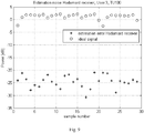
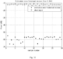
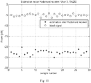
- TUx, HTx and RAx are the usual abbreviations for Typical Urban, Hilly Terrain, Rural Area at a speed of x km/h. It can be seen that at low speeds the sub-channels are, for practical purposes, orthogonal, and separation of the users is possible. At high speeds the users are no longer truly orthogonal and a noise floor is introduced. This may affect the performance of the demodulator. On the other hand, the separation algorithm also reduces the thermal noise power by 6 dB.
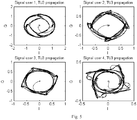
- Fig. 5 shows all the user signals separately, including Rx filtering in the receiver.
- Fig. 5 shows baseband signals for 4 users undergoing independent fading. It is meant for illustrative purposes only; the signals do not exist individually after the transmitters have emitted the electromagnetic waves.
- Fig. 6 depicts the received signal, without any thermal noise. It is obtained by the superposition of the 4 signals in Fig. 5 . The signal sampled at the symbol rate is also shown. This is the digital signal that is fed to the user separation algorithm.
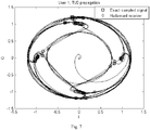
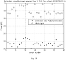
- Fig. 7 shows the ideal and estimated I and Q components of the digital signal for one of the users.
- Figs. 8 - 13 illustrate the estimation error introduced by the user separation algorithm.
- "Hadamard receiver" refers to the method described herein.
- the above transmission techniques all divide the available channel bandwidth equally between the sub-channels of the different users in the same slot. In some cases it can be envisaged that a greater flexibility would be advantageous. To address this need the possibility to divide the available channel bandwidth unequally between the sub-channels can be added.
- the technique described above creates 2 m orthogonal sub-channels, each sub-channel constituting 1/2 m of the available channel bandwidth in a slot.
- the receiver as described above for equal bandwidth is configured so that the received signal is split into 2 m time blocks, and the time blocks collected into a block matrix.
- the block matrix is multiplied by the k th row of the Hadamard matrix used in the transmitter.
- the block matrix is further divided into 2 n k block matrices corresponding to the 2 n k transmitted vectors (the division is user-specific and is defined by the order the vectors are transmitted).
- Each block matrix is multiplied to a sub-vector of row ⁇ k of the Hadamard matrix to separate each transmitted vector of user k from the signals of the other users.
- the ratio 2 n k /2 m will here be denoted the sub-channel rate .
- the sub-channel rate may be different for different users.
- the methods in the transmitter and receiver for a given user k depend only on the rate of that user, not on the rate of the other users. Despite this, orthogonality is maintained between the sub-channels as long as the total rate sums up to 1 (or less) and the set of rows of the Hadamard matrix to use in the transmitter/receiver is selected wisely as will be described below.
- ⁇ denotes the Kronecker product, 1 M ⁇ N , is a matrix of ones of size M ⁇ N , and we use the Matlab shorthand A ( k ,:) or A ( k , m : n ) to denote a row or a slice of a row of the matrix A .
- N v 2 m (for some m > 0) be the multiplexing order of the channel. This number gives the number of vectors of N payload bits to be transmitted during a burst. If the sub-channel rate is 1/2 m for all users, the multiplexing order is equal to N u , the number of users sharing the channel, but in general N u ⁇ N v .
- b ⁇ k , 1 , ⁇ , b ⁇ k , 2 n k be the 2 n k vectors of payload bits for user k. In order to avoid degenerate cases where there is just one user, it is assumed that n k ⁇ m.
- t ⁇ k left , t ⁇ k right be the vectors of left and right tail bits and s k be the vector of training sequence bits.
- the bit flip operation and the generalized Hadamard matrix product (denoted ⁇ and ⁇ respectively) are defined as above.
- the formatted burst for user k consists of tail bits, training sequence bits and 2 m - n k repetitions of the block of payload bits ⁇ b ⁇ k , 1 , ⁇ , b ⁇ k , 2 n k ⁇ , each vector being modified by bit flip according to the sign of the entries in row ⁇ k of the Hadamard matrix.
- the numbers in the nodes denote matrix row numbers r k .
- the transmitter can be the same as for a transmitter described above in conjunction with Fig. 2 .
- a first example will now be given that illustrates the teachings for unequal sub-channel bandwidth.
- a total of 4 users are multiplexed together using multiplexing order 8, creating one sub-channel of rate 1 ⁇ 2, one sub-channel of rate 1 ⁇ 4 and two sub-channels of rate 1/8.
- Table 1 Example of row selection for the Hadamard matrix H 3 . k n k 2 m-n k 2 n k ⁇ k Sub-channel rate 1 0 8 1 1 1/8 2 2 2 4 5 1/2 3 1 4 2 3 1/4 4 0 8 1 2 1/8
- a simplification of the receiver processing can be achieved by adding a cyclic prefix at beginning of each half burst.
- L ⁇ 0 be the length of the cyclic prefix. It is a design parameter. A value around 4, 5 or 6 should be appropriate for GSM.
- u k ( i )( j ) is here used to denote the j th element of the i th vector in the block vector u k .
- Fig. 17 shows exemplary transmitter processing steps performed by on user for one user. Each user using the same channel performs similar processing.
- step S1701 the transmitter receives as input the 2 n k blocks of user specific payload bits and the multiplexing order N v .
- step S1701 the input blocks are repeated such that the output from step S1701 consists of 2 m-n k repetitions of the input blocks.
- Step S1703 takes as input the block of repeated bits and the row index.
- a row of a Hadamard matrix is chosen.
- Each user will choose a different row.
- the row index to be used for each user needs to be selected depending on the sub-channel rates for all users.
- Each entry in the row is either one or minus one.
- the bits in each block will be left intact or will be flipped according to the sign of the corresponding entry. For example if the third entry in the row is a one, then the third block is left unchanged. But if the third entry in the row is a minus one, then all the bits in the third block are flipped.
- step S1703 modifies the input block by bit flipping some sub-blocks according to a row of a Hadamard matrix.
- Step S1705 takes as input the repeated, flipped, payload bits for the user and divides them into two halves of equal length.
- step S1707 a cyclic prefix before every second block.
- a step S1709 performs burst formatting is performed, Guard, tail and training bits are inserted, and placed in a predefined order together with the two halves of the payload bits.
- Guard bits are added at the beginning, followed by tail bits, followed by the first half of the payload, then training sequence bits are added, followed by the second half of the payload bits. Finally more tail bits and guard bits are added.
- step S1711 the formatted burst to a modulator For example to a GMSK modulator as described in 3GPP TS 45.004 v9.1.0.
- r(n) denote the received signal.
- ⁇ k ( n ) ⁇ 1 - 2 b k ( n ) denote the payload symbols for user k , and let n 0 be the start of the payload symbols.
- N t be the number of training bits.
- N t be the number of training bits.
- the receiver processing steps are illustrated in Fig. 18 .
- Fig. 18 depicts receiver side processing for one user, in case a cyclic prefix is used at the transmitter. It assumes a single antenna receiver. This is typically the most challenging case for multi-user reception, and generalizations to more antenna branches are straightforward.
- step S1801 received digital signal is input, the multiplexing order and the hypothesized synchronization position are also obtained in step S1801.
- step S1801 the received signal is partitioned into time blocks of equal length.
- step S1803 the partitioned signal is stacked to form a column block vector.
- a step 1805 the number of blocks of data bits 2 n k and the row index ⁇ k of user k are input. Also the column block vector of received samples R and row ⁇ k of the Hadamard matrix are each divided into 2 n k sub-vectors, for example as described above. The sub-vectors are block-wise multiplied. This means that the entries of the block vector are multiplied by one or minus one. Multiplication of vector and scalar is performed as usual, all entries of the vector are multiplied by the scalar, in this case either one or minus one. The output is 2 n k vectors representing the data bits transmitted by user k . These vectors contain only energy from a chosen user, while the energy from all other users has been cancelled.
- the vectors are sent to a demodulator for example to an ordinary GMSK demodulator.
- the receiver is modified accordingly for the multi-rate case.
- time dispersive channel can be modeled as addition of one or more time shifted versions of the transmitted signal.
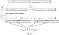
- the inter-symbol interference into the subsequent time blocks marked with circles in Fig. 19 can be described by the generalized Hadamard matrix product of the last L bits of the transmitted bit vector b k ,1 by a row of a column-permuted version of the Hadamard matrix H 2 , here denoted H 2 ° .
- the payload bits of each user are repeated blockwise M times.
- the users are assigned rates 1/R1, 1/R2,...,1/RM by the network.
- the numbers R1,...,RM are positive integers.
- 1/R1 + 1/R2 + ... +1/RM ⁇ 1.
- the k-th user needs to know its rate Rk, but it does not need to know the rate of the other users.
- the k-th user repeats its data block Rk times. In other words the rate is the reciprocal of the number of repetitions.
- each user is assigned a rate.
- user k is assigned the number of repetitions Rk, which is the reciprocal of the rate 1/Rk.
- the selection of the size of the Hadamard matrix will correspond to the inverse of the rate of the user with the lowest rate.
- the size of the Hadamard matrix needs to have a size of 8x8.
- each user can select a unique row in the Hadamard matrix to be used when determining which bits to flip.
- the rate will correspond to the number of users in the slot so for the case with equal number of users the required size of the Hadamard matrix will correspond to the number of users.
- Fig. 14 depicts a transmitter 701 for generating and transmitting signals as described herein.
- the transmitter can be implemented in a mobile station.
- the transmitter can also be implemented in a radio base station.
- the transmitter 701 comprises controller circuitry 703 for performing the various steps required when forming a signal for transmission in accordance with the principles described herein.
- the controller circuitry can be implemented using suitable hardware and or software.
- the hardware can comprise one or many processors that can be arranged to execute software stored in a readable storage media.
- the processor(s) can be implemented by a single dedicated processor, by a single shared processor, or by a plurality of individual processors, some of which may be shared or distributed.
- a processor or may include, without limitation, digital signal processor (DSP) hardware, ASIC hardware, read only memory (ROM), random access memory (RAM), and/or other storage media.
- DSP digital signal processor
- Fig. 15 depicts a receiver 701 for receiving and processing received signals as described herein.
- the receiver can be implemented in a radio base station.
- the receiver can also be implemented in a mobile station.
- the receiver 301 comprises controller circuitry 703 for performing the various steps required when receiving signals in accordance with the principles described herein.
- the controller circuitry can be implemented using suitable hardware and or software.
- the hardware can comprise one or many processors that can be arranged to execute software stored in a readable storage media.
- the processor(s) can be implemented by a single dedicated processor, by a single shared processor, or by a plurality of individual processors, some of which may be shared or distributed.
- a processor or may include, without limitation, digital signal processor (DSP) hardware, ASIC hardware, read only memory (ROM), random access memory (RAM), and/or other storage media.
- DSP digital signal processor
- ASIC application specific integrated circuit
- ROM read only memory
- RAM random access memory
- Using the transmission methods and devices as described herein provides a way to multiplex several modulated signals into one time slot.
- Using the methods and devices as described herein can provide the benefits that orthogonal channels are created, and the method can be used in both uplink and downlink transmissions.
- truly orthogonal channels can be achieved meaning that perfect orthogonality (in the frequency domain) can be achieved for two or more users.
- the transmitters may employ GMSK modulation or other form of CPM, which due to its constant envelope, is very convenient for use in mobile stations and leads to energy efficiency. Further a single antenna receiver is enough to receive and demodulate more than 2 users.
- GMSK demodulator may be used.
- the methods and devices may be used in conjunction with Multiple Input Multiple Output (MIMO) or Multi-User MIMO (MU-MIMO). They can be used to create shared signaling channels (e.g. fast feedback channels in GSM), or shared data channels.
- MIMO Multiple Input Multiple Output
- MU-MIMO Multi-User MIMO
- GSM Global System for Mobile Communications
- they may be of use in satellite communications systems or maritime communications systems, whenever the energy efficiency calls for constant envelope modulation and whenever there is a need to multiplex several users into one time slot. Also burst formatting of today can be kept intact and that legacy mobiles supporting GMSK modulation can be used with additional complexity of bit flipping and bit repetition.
Landscapes
- Engineering & Computer Science (AREA)
- Computer Networks & Wireless Communication (AREA)
- Signal Processing (AREA)
- Physics & Mathematics (AREA)
- Discrete Mathematics (AREA)
- General Physics & Mathematics (AREA)
- Mathematical Physics (AREA)
- Quality & Reliability (AREA)
- Digital Transmission Methods That Use Modulated Carrier Waves (AREA)
- Mobile Radio Communication Systems (AREA)
Claims (14)
- Procédé de modulation d'un signal qui est destiné à être émis depuis un émetteur (701), dans lequel le signal émis est émis dans une fenêtre temporelle qui comporte de multiples utilisateurs au nombre de Nu, avec Nu ≤ 2m, où 2m est un ordre de multiplexage de canal, le procédé comprenant, pour un utilisateur k, les étapes consistant à :- obtenir (S1) des bits de charge utile spécifiques d'utilisateur selon 2 n
k blocs et selon un débit de 2 nk /2m selon lesquels l'émetteur (701) doit émettre dans la fenêtre temporelle, où 0 < nk < m ;- répéter (S1) les blocs de manière à former un bloc combiné, dans lequel les blocs sont répétés un nombre de fois qui est égal à l'inverse du débit selon lequel l'émetteur (701) émet dans la fenêtre temporelle et dans lequel les bits dans chaque bloc répété sont ensuite laissés intacts ou sont inversés, dans lequel les blocs qui sont inversés sont sélectionnés conformément à un signe d'entrées d'une rangée d'une matrice 2m x 2m de Hadamard, et dans lequel la rangée sélectionnée est spécifique d'utilisateur parmi les multiples utilisateurs de la fenêtre temporelle ; et- le formatage par salve (S5) et la modulation (S6) du bloc combiné de bits de charge utile en utilisant une modulation de phase continue non linéaire. - Procédé selon la revendication 1, dans lequel le nombre de colonnes de la matrice de Hadamard est au moins l'inverse du débit selon lequel l'émetteur (701) émet dans la fenêtre temporelle.
- Procédé selon l'une quelconque des revendications précédentes, comprenant en outre la division du bloc combiné selon deux moitiés de bloc égales.
- Procédé selon la revendication 3, dans lequel un préfixe cyclique est ajouté à chacune des deux moitiés de bloc de longueurs égales.
- Procédé selon l'une quelconque des revendications précédentes, dans lequel la salve est formatée conformément à un format de salve GSM.
- Procédé selon l'une quelconque des revendications précédentes, dans lequel la salve est modulée en utilisant un modulateur GMSK.
- Procédé selon l'une quelconque des revendications précédentes, dans lequel le signal modulé est émis depuis une station mobile.
- Procédé selon l'une quelconque des revendications précédentes, dans lequel la bande passante dans la fenêtre temporelle est divisée de manière inégale entre les utilisateurs dans la fenêtre temporelle.
- Procédé selon l'une quelconque des revendications précédentes, dans lequel la bande passante dans la fenêtre temporelle est divisée de manière égale entre les utilisateurs dans la fenêtre temporelle.
- Procédé de réception d'un signal modulé qui provient d'un équipement d'utilisateur qui émet un signal dans une fenêtre temporelle qui comporte de multiples utilisateurs au nombre de Nu, avec Nu ≤ 2m, où 2m est un ordre de multiplexage de canal, le procédé comprenant, pour un utilisateur k, les étapes consistant à :- obtenir (S11) des bits de charge utile spécifiques d'utilisateur selon 2 n
k blocs et selon un débit de 2 nk /2m qui sont utilisés par l'équipement d'utilisateur pour émettre le signal dans la fenêtre temporelle, où 0 < nk < m, dans lequel le signal d'émission convoie un bloc combiné de bits de charge utile qui sont générés par l'équipement d'utilisateur en répétant les blocs de bits un nombre de fois qui est égal à l'inverse du débit d'émission par l'équipement d'utilisateur ;- obtenir (S11) une rangée d'une matrice 2m x 2m de Hadamard qui est utilisée par l'utilisateur, dans lequel la rangée sélectionnée est spécifique d'utilisateur parmi les multiples utilisateurs de la fenêtre temporelle ;- déterminer (S11) la position de synchronisation ;- partitionner (S11) le signal reçu selon des blocs de longueurs égales, dans lequel le nombre de blocs correspond à l'inverse du débit de l'utilisateur ;- remettre dans le sens initial (S 13) les échantillons dans chaque bloc partitionné de telle sorte que tous les blocs qui sont inversés au niveau d'un émetteur (701) soient multipliés par -1 ;- former (S 14) un bloc de résultat en additionnant par élément les entrées dans tous les blocs partitionnés ; et- démoduler le bloc de résultat. - Émetteur (701) adapté de manière à moduler un signal, dans lequel le signal est émis dans une fenêtre temporelle qui comporte de multiples utilisateurs au nombre de Nu, avec Nu ≤ 2m, où 2m est un ordre de multiplexage de canal, l'émetteur (701) comprenant, pour un utilisateur k, un circuit de contrôleur (703) pour :- obtenir des bits de charge utile spécifiques d'utilisateur selon 2 n
k blocs et selon un débit de 2 nk /2m selon lesquels l'émetteur (701) doit émettre dans la fenêtre temporelle, où 0 < nk < m, l'émetteur (701) comprenant en outre un circuit de contrôleur (703) pour :- répéter les blocs de manière à former un bloc combiné, dan lequel les blocs sont répétés un nombre de fois qui est égal à l'inverse du débit selon lequel l'émetteur (701) émet dans la fenêtre temporelle et dans lequel les bits dans chaque bloc répété sont ensuite laissés intacts ou sont inversés, dans lequel les blocs qui sont inversés sont sélectionnés conformément à un signe d'entrées d'une rangée d'une matrice 2m x 2m de Hadamard, et dans lequel la rangée sélectionnée est spécifique d'utilisateur parmi les multiples utilisateurs de la fenêtre temporelle ; et- formater par salve et moduler le bloc combiné de bits de charge utile en utilisant une modulation de phase continue non linéaire. - Émetteur (701) selon la revendication 11, dans lequel le nombre de colonnes de la matrice de Hadamard est au moins l'inverse du débit selon lequel l'émetteur (701) est adapté de manière à émettre dans la fenêtre temporelle.
- Émetteur (701) selon l'une quelconque des revendications précédentes, comprenant en outre la division du bloc combiné selon deux moitiés de bloc égales.
- Récepteur (801) pour recevoir un signal modulé qui provient d'un équipement d'utilisateur qui émet un signal dans une fenêtre temporelle qui comporte de multiples utilisateurs au nombre de Nu, avec Nu ≤ 2m, où 2m est un ordre de multiplexage de canal, le récepteur (801) comprenant, pour un utilisateur k, un circuit de contrôleur (803) pour :- obtenir des bits de charge utile spécifiques d'utilisateur selon 2 n
k blocs et selon un débit de 2 nk /2m qui sont utilisés par l'équipement d'utilisateur pour émettre le signal dans la fenêtre temporelle, où 0 < nk < m, dans lequel le signal d'émission convoie un bloc combiné de bits de charge utile qui sont générés par l'équipement d'utilisateur en répétant les blocs de bits un nombre de fois qui est égal à l'inverse du débit d'émission par l'équipement d'utilisateur ;- obtenir une rangée d'une matrice 2m x 2m de Hadamard qui est utilisée par l'utilisateur, dans lequel la rangée sélectionnée est spécifique d'utilisateur parmi les multiples utilisateurs de la fenêtre temporelle ;- déterminer la position de synchronisation ;- partitionner le signal reçu selon des blocs de longueurs égales, dans lequel le nombre de blocs correspond à l'inverse du débit de l'utilisateur ;- remettre dans le sens initial les échantillons dans chaque bloc partitionné de telle sorte que tous les blocs qui sont inversés au niveau d'un émetteur (701) soient multipliés par -1 ;- former un bloc de résultat en additionnant par élément les entrées dans tous les blocs partitionnés ; et- démoduler le bloc de résultat.
Applications Claiming Priority (2)
| Application Number | Priority Date | Filing Date | Title |
|---|---|---|---|
| US201261625313P | 2012-04-17 | 2012-04-17 | |
| PCT/SE2012/050933 WO2013158005A1 (fr) | 2012-04-17 | 2012-09-03 | Procédés et dispositifs pour la transmission de signaux dans un système de télécommunication |
Publications (3)
| Publication Number | Publication Date |
|---|---|
| EP2839617A1 EP2839617A1 (fr) | 2015-02-25 |
| EP2839617A4 EP2839617A4 (fr) | 2015-08-19 |
| EP2839617B1 true EP2839617B1 (fr) | 2017-11-08 |
Family
ID=49383812
Family Applications (1)
| Application Number | Title | Priority Date | Filing Date |
|---|---|---|---|
| EP12874625.2A Active EP2839617B1 (fr) | 2012-04-17 | 2012-09-03 | Procédés et dispositifs pour la transmission de signaux dans un système de télécommunication |
Country Status (3)
| Country | Link |
|---|---|
| US (1) | US9332541B2 (fr) |
| EP (1) | EP2839617B1 (fr) |
| WO (1) | WO2013158005A1 (fr) |
Families Citing this family (9)
| Publication number | Priority date | Publication date | Assignee | Title |
|---|---|---|---|---|
| US9609631B2 (en) * | 2012-01-20 | 2017-03-28 | Mediatek Inc. | Wireless communication apparatuses and related methods |
| US9306691B2 (en) | 2012-04-02 | 2016-04-05 | Telefonaktiebolaget L M Ericsson | Methods and devices for transmission of signals in a telecommunication system |
| US9794780B2 (en) | 2014-03-21 | 2017-10-17 | Telefonaktiebolaget Lm Ericsson (Publ) | Mobile station, access node and various methods for implementing an accelerated system access procedure |
| EP3142274B1 (fr) | 2014-05-09 | 2019-07-03 | Panasonic Intellectual Property Corporation of America | Terminal, station de base, procédé de transmission et procédé de réception |
| US9673891B2 (en) | 2014-05-09 | 2017-06-06 | Telefonaktiebolaget Lm Ericsson (Publ) | Code division multiple access (CDMA) overlay to other multiplexing scheme |
| US9780980B2 (en) * | 2014-05-20 | 2017-10-03 | Telefonaktiebolaget Lm Ericsson (Publ) | Transmitter, a receiver, and methods therein |
| WO2016028215A1 (fr) | 2014-08-20 | 2016-02-25 | Telefonaktiebolaget L M Ericsson (Publ) | Nœud de réseau radio, dispositif sans fil, et procédés correspondants, via une modulation gmsk utilisant un indice de modulation négatif |
| US10159077B2 (en) | 2015-04-14 | 2018-12-18 | Telefonaktiebolaget Lm Ericsson (Publ) | Methods and arrangements relating to sending information repeatedly from a sending node to a receiving node in a cell of a wireless communication network |
| CN111357222B (zh) * | 2017-10-30 | 2022-07-22 | 瑞典爱立信有限公司 | 解码包括编码的数据符号的信号的方法和设备 |
Family Cites Families (16)
| Publication number | Priority date | Publication date | Assignee | Title |
|---|---|---|---|---|
| US6215762B1 (en) | 1997-07-22 | 2001-04-10 | Ericsson Inc. | Communication system and method with orthogonal block encoding |
| US20040196861A1 (en) * | 2001-01-12 | 2004-10-07 | Joseph Rinchiuso | Packet data transmission within a broad-band communication system |
| US6947446B2 (en) * | 2001-01-16 | 2005-09-20 | Motorola, Inc. | Slot format and acknowledgement method for a wireless communication system |
| US8489949B2 (en) * | 2003-08-05 | 2013-07-16 | Qualcomm Incorporated | Combining grant, acknowledgement, and rate control commands |
| US8908496B2 (en) * | 2003-09-09 | 2014-12-09 | Qualcomm Incorporated | Incremental redundancy transmission in a MIMO communication system |
| US7352795B2 (en) | 2005-05-04 | 2008-04-01 | Harris Corporation | System and method for communicating data using constant amplitude waveform with hybrid orthogonal and MSK or GMSK modulation |
| US7889806B2 (en) * | 2006-07-20 | 2011-02-15 | Intel Corporation | Method and apparatus to improve performance in a multicarrier MIMO channel using the hadamard transform |
| US8755770B2 (en) * | 2006-08-01 | 2014-06-17 | L-3 Communications Corporation | Methods for identifying wireless devices connected to potentially threatening devices |
| AU2011202942B2 (en) | 2007-09-12 | 2012-08-23 | Qualcomm Incorporated | Capacity increasing devices and methods for wireless communication |
| US8767637B2 (en) * | 2007-11-05 | 2014-07-01 | Apple Inc. | Methods and systems for resource allocation |
| US8788918B2 (en) * | 2008-03-20 | 2014-07-22 | Marvell World Trade Ltd. | Block encoding with a variable rate block code |
| KR101743123B1 (ko) * | 2009-05-21 | 2017-06-15 | 삼성전자주식회사 | 디지털 방송 송신기, 디지털 방송 수신기 및 그들의 스트림 구성 및 처리 방법 |
| JP5420339B2 (ja) * | 2009-07-29 | 2014-02-19 | 京セラ株式会社 | 無線端末及び伝送速度予測方法 |
| US8543863B2 (en) * | 2009-11-18 | 2013-09-24 | Microsoft Corporation | Efficiency of hardware memory access using dynamically replicated memory |
| US8331478B2 (en) * | 2010-01-08 | 2012-12-11 | Research In Motion Limited | Transmit diversity using low code rate spatial multiplexing |
| WO2011136559A2 (fr) * | 2010-04-27 | 2011-11-03 | 엘지전자 주식회사 | Procédé et appareil pour la transmission d'informations de commande de liaison montante dans un système de communication sans fil |
-
2012
- 2012-09-03 WO PCT/SE2012/050933 patent/WO2013158005A1/fr not_active Ceased
- 2012-09-03 EP EP12874625.2A patent/EP2839617B1/fr active Active
- 2012-09-03 US US13/635,624 patent/US9332541B2/en active Active
Non-Patent Citations (1)
| Title |
|---|
| None * |
Also Published As
| Publication number | Publication date |
|---|---|
| EP2839617A1 (fr) | 2015-02-25 |
| US9332541B2 (en) | 2016-05-03 |
| EP2839617A4 (fr) | 2015-08-19 |
| US20130272273A1 (en) | 2013-10-17 |
| WO2013158005A1 (fr) | 2013-10-24 |
Similar Documents
| Publication | Publication Date | Title |
|---|---|---|
| US9332541B2 (en) | Methods and devices for transmission of signals in a telecommunication system | |
| CN108028669B (zh) | 在数字混沌协作网络中通信数据的方法和设备 | |
| US8582622B2 (en) | Spread-spectrum coding of data bursts | |
| US5555268A (en) | Multicode direct sequence spread spectrum | |
| US10277438B2 (en) | Method and apparatus for communicating data in a digital chaos communication system | |
| US20180034676A1 (en) | Method and apparatus for transmitting a signal | |
| US20060109925A1 (en) | Method and apparatus for error reduction in an orthogonal modulation system | |
| Chung | Spectral precoding for rectangularly pulsed OFDM | |
| US20160301551A1 (en) | Radio Frame for Communicating Data in a Digital Chaos Communication System | |
| EP2371068B1 (fr) | Système de communication, unités de communication et procédé pour utiliser un schéma d'émission pilote | |
| EP2124371B1 (fr) | Dispositif de réception, dispositif de transmission, système de transmission/réception radio et procédé de réception radio | |
| EP3219036B1 (fr) | Noeud d'émission et procédés mis en oeuvre dans ce dernier | |
| WO2017010623A1 (fr) | Procédé permettant d'estimer un canal d'auto-brouillage non linéaire dans un système de communication sans fil et dispositif pour ce dernier | |
| US9306691B2 (en) | Methods and devices for transmission of signals in a telecommunication system | |
| US20090175160A1 (en) | Precoder Matrix for Multichannel Transmission | |
| CN101208878B (zh) | 发射分集方案 | |
| US9998309B2 (en) | Transmitter, a receiver, and methods therein | |
| US9780980B2 (en) | Transmitter, a receiver, and methods therein | |
| US9270398B2 (en) | Methods and devices for transmission of signals in a telecommunication system | |
| EP3544202B1 (fr) | Insertion d'un signal de référence pré-dft pour stbc à symbole unique | |
| US20250202752A1 (en) | Single sideband dft-s-ofdm |
Legal Events
| Date | Code | Title | Description |
|---|---|---|---|
| PUAI | Public reference made under article 153(3) epc to a published international application that has entered the european phase |
Free format text: ORIGINAL CODE: 0009012 |
|
| 17P | Request for examination filed |
Effective date: 20140821 |
|
| AK | Designated contracting states |
Kind code of ref document: A1 Designated state(s): AL AT BE BG CH CY CZ DE DK EE ES FI FR GB GR HR HU IE IS IT LI LT LU LV MC MK MT NL NO PL PT RO RS SE SI SK SM TR |
|
| AX | Request for extension of the european patent |
Extension state: BA ME |
|
| DAX | Request for extension of the european patent (deleted) | ||
| RA4 | Supplementary search report drawn up and despatched (corrected) |
Effective date: 20150722 |
|
| RIC1 | Information provided on ipc code assigned before grant |
Ipc: H04L 27/18 20060101AFI20150716BHEP Ipc: H04J 13/00 20110101ALI20150716BHEP Ipc: H04L 27/20 20060101ALN20150716BHEP |
|
| 17Q | First examination report despatched |
Effective date: 20161007 |
|
| STAA | Information on the status of an ep patent application or granted ep patent |
Free format text: STATUS: EXAMINATION IS IN PROGRESS |
|
| GRAP | Despatch of communication of intention to grant a patent |
Free format text: ORIGINAL CODE: EPIDOSNIGR1 |
|
| STAA | Information on the status of an ep patent application or granted ep patent |
Free format text: STATUS: GRANT OF PATENT IS INTENDED |
|
| RIC1 | Information provided on ipc code assigned before grant |
Ipc: H04L 27/20 20060101ALN20170316BHEP Ipc: H04L 27/18 20060101AFI20170316BHEP |
|
| INTG | Intention to grant announced |
Effective date: 20170330 |
|
| GRAS | Grant fee paid |
Free format text: ORIGINAL CODE: EPIDOSNIGR3 |
|
| GRAA | (expected) grant |
Free format text: ORIGINAL CODE: 0009210 |
|
| STAA | Information on the status of an ep patent application or granted ep patent |
Free format text: STATUS: THE PATENT HAS BEEN GRANTED |
|
| AK | Designated contracting states |
Kind code of ref document: B1 Designated state(s): AL AT BE BG CH CY CZ DE DK EE ES FI FR GB GR HR HU IE IS IT LI LT LU LV MC MK MT NL NO PL PT RO RS SE SI SK SM TR |
|
| REG | Reference to a national code |
Ref country code: GB Ref legal event code: FG4D |
|
| REG | Reference to a national code |
Ref country code: CH Ref legal event code: EP Ref country code: AT Ref legal event code: REF Ref document number: 945168 Country of ref document: AT Kind code of ref document: T Effective date: 20171115 |
|
| REG | Reference to a national code |
Ref country code: IE Ref legal event code: FG4D |
|
| REG | Reference to a national code |
Ref country code: DE Ref legal event code: R096 Ref document number: 602012039652 Country of ref document: DE |
|
| REG | Reference to a national code |
Ref country code: NL Ref legal event code: MP Effective date: 20171108 |
|
| REG | Reference to a national code |
Ref country code: LT Ref legal event code: MG4D |
|
| REG | Reference to a national code |
Ref country code: AT Ref legal event code: MK05 Ref document number: 945168 Country of ref document: AT Kind code of ref document: T Effective date: 20171108 |
|
| PG25 | Lapsed in a contracting state [announced via postgrant information from national office to epo] |
Ref country code: NL Free format text: LAPSE BECAUSE OF FAILURE TO SUBMIT A TRANSLATION OF THE DESCRIPTION OR TO PAY THE FEE WITHIN THE PRESCRIBED TIME-LIMIT Effective date: 20171108 Ref country code: LT Free format text: LAPSE BECAUSE OF FAILURE TO SUBMIT A TRANSLATION OF THE DESCRIPTION OR TO PAY THE FEE WITHIN THE PRESCRIBED TIME-LIMIT Effective date: 20171108 Ref country code: ES Free format text: LAPSE BECAUSE OF FAILURE TO SUBMIT A TRANSLATION OF THE DESCRIPTION OR TO PAY THE FEE WITHIN THE PRESCRIBED TIME-LIMIT Effective date: 20171108 Ref country code: SE Free format text: LAPSE BECAUSE OF FAILURE TO SUBMIT A TRANSLATION OF THE DESCRIPTION OR TO PAY THE FEE WITHIN THE PRESCRIBED TIME-LIMIT Effective date: 20171108 Ref country code: NO Free format text: LAPSE BECAUSE OF FAILURE TO SUBMIT A TRANSLATION OF THE DESCRIPTION OR TO PAY THE FEE WITHIN THE PRESCRIBED TIME-LIMIT Effective date: 20180208 Ref country code: FI Free format text: LAPSE BECAUSE OF FAILURE TO SUBMIT A TRANSLATION OF THE DESCRIPTION OR TO PAY THE FEE WITHIN THE PRESCRIBED TIME-LIMIT Effective date: 20171108 |
|
| PG25 | Lapsed in a contracting state [announced via postgrant information from national office to epo] |
Ref country code: RS Free format text: LAPSE BECAUSE OF FAILURE TO SUBMIT A TRANSLATION OF THE DESCRIPTION OR TO PAY THE FEE WITHIN THE PRESCRIBED TIME-LIMIT Effective date: 20171108 Ref country code: GR Free format text: LAPSE BECAUSE OF FAILURE TO SUBMIT A TRANSLATION OF THE DESCRIPTION OR TO PAY THE FEE WITHIN THE PRESCRIBED TIME-LIMIT Effective date: 20180209 Ref country code: IS Free format text: LAPSE BECAUSE OF FAILURE TO SUBMIT A TRANSLATION OF THE DESCRIPTION OR TO PAY THE FEE WITHIN THE PRESCRIBED TIME-LIMIT Effective date: 20180308 Ref country code: BG Free format text: LAPSE BECAUSE OF FAILURE TO SUBMIT A TRANSLATION OF THE DESCRIPTION OR TO PAY THE FEE WITHIN THE PRESCRIBED TIME-LIMIT Effective date: 20180208 Ref country code: LV Free format text: LAPSE BECAUSE OF FAILURE TO SUBMIT A TRANSLATION OF THE DESCRIPTION OR TO PAY THE FEE WITHIN THE PRESCRIBED TIME-LIMIT Effective date: 20171108 Ref country code: HR Free format text: LAPSE BECAUSE OF FAILURE TO SUBMIT A TRANSLATION OF THE DESCRIPTION OR TO PAY THE FEE WITHIN THE PRESCRIBED TIME-LIMIT Effective date: 20171108 Ref country code: AT Free format text: LAPSE BECAUSE OF FAILURE TO SUBMIT A TRANSLATION OF THE DESCRIPTION OR TO PAY THE FEE WITHIN THE PRESCRIBED TIME-LIMIT Effective date: 20171108 |
|
| PG25 | Lapsed in a contracting state [announced via postgrant information from national office to epo] |
Ref country code: SK Free format text: LAPSE BECAUSE OF FAILURE TO SUBMIT A TRANSLATION OF THE DESCRIPTION OR TO PAY THE FEE WITHIN THE PRESCRIBED TIME-LIMIT Effective date: 20171108 Ref country code: EE Free format text: LAPSE BECAUSE OF FAILURE TO SUBMIT A TRANSLATION OF THE DESCRIPTION OR TO PAY THE FEE WITHIN THE PRESCRIBED TIME-LIMIT Effective date: 20171108 Ref country code: CY Free format text: LAPSE BECAUSE OF FAILURE TO SUBMIT A TRANSLATION OF THE DESCRIPTION OR TO PAY THE FEE WITHIN THE PRESCRIBED TIME-LIMIT Effective date: 20171108 Ref country code: DK Free format text: LAPSE BECAUSE OF FAILURE TO SUBMIT A TRANSLATION OF THE DESCRIPTION OR TO PAY THE FEE WITHIN THE PRESCRIBED TIME-LIMIT Effective date: 20171108 Ref country code: CZ Free format text: LAPSE BECAUSE OF FAILURE TO SUBMIT A TRANSLATION OF THE DESCRIPTION OR TO PAY THE FEE WITHIN THE PRESCRIBED TIME-LIMIT Effective date: 20171108 |
|
| REG | Reference to a national code |
Ref country code: DE Ref legal event code: R097 Ref document number: 602012039652 Country of ref document: DE |
|
| PG25 | Lapsed in a contracting state [announced via postgrant information from national office to epo] |
Ref country code: SM Free format text: LAPSE BECAUSE OF FAILURE TO SUBMIT A TRANSLATION OF THE DESCRIPTION OR TO PAY THE FEE WITHIN THE PRESCRIBED TIME-LIMIT Effective date: 20171108 Ref country code: PL Free format text: LAPSE BECAUSE OF FAILURE TO SUBMIT A TRANSLATION OF THE DESCRIPTION OR TO PAY THE FEE WITHIN THE PRESCRIBED TIME-LIMIT Effective date: 20171108 Ref country code: IT Free format text: LAPSE BECAUSE OF FAILURE TO SUBMIT A TRANSLATION OF THE DESCRIPTION OR TO PAY THE FEE WITHIN THE PRESCRIBED TIME-LIMIT Effective date: 20171108 Ref country code: RO Free format text: LAPSE BECAUSE OF FAILURE TO SUBMIT A TRANSLATION OF THE DESCRIPTION OR TO PAY THE FEE WITHIN THE PRESCRIBED TIME-LIMIT Effective date: 20171108 |
|
| PLBE | No opposition filed within time limit |
Free format text: ORIGINAL CODE: 0009261 |
|
| STAA | Information on the status of an ep patent application or granted ep patent |
Free format text: STATUS: NO OPPOSITION FILED WITHIN TIME LIMIT |
|
| 26N | No opposition filed |
Effective date: 20180809 |
|
| PG25 | Lapsed in a contracting state [announced via postgrant information from national office to epo] |
Ref country code: SI Free format text: LAPSE BECAUSE OF FAILURE TO SUBMIT A TRANSLATION OF THE DESCRIPTION OR TO PAY THE FEE WITHIN THE PRESCRIBED TIME-LIMIT Effective date: 20171108 |
|
| PG25 | Lapsed in a contracting state [announced via postgrant information from national office to epo] |
Ref country code: MC Free format text: LAPSE BECAUSE OF FAILURE TO SUBMIT A TRANSLATION OF THE DESCRIPTION OR TO PAY THE FEE WITHIN THE PRESCRIBED TIME-LIMIT Effective date: 20171108 |
|
| REG | Reference to a national code |
Ref country code: CH Ref legal event code: PL |
|
| REG | Reference to a national code |
Ref country code: BE Ref legal event code: MM Effective date: 20180930 |
|
| REG | Reference to a national code |
Ref country code: IE Ref legal event code: MM4A |
|
| PG25 | Lapsed in a contracting state [announced via postgrant information from national office to epo] |
Ref country code: LU Free format text: LAPSE BECAUSE OF NON-PAYMENT OF DUE FEES Effective date: 20180903 |
|
| PG25 | Lapsed in a contracting state [announced via postgrant information from national office to epo] |
Ref country code: IE Free format text: LAPSE BECAUSE OF NON-PAYMENT OF DUE FEES Effective date: 20180903 |
|
| PG25 | Lapsed in a contracting state [announced via postgrant information from national office to epo] |
Ref country code: LI Free format text: LAPSE BECAUSE OF NON-PAYMENT OF DUE FEES Effective date: 20180930 Ref country code: CH Free format text: LAPSE BECAUSE OF NON-PAYMENT OF DUE FEES Effective date: 20180930 Ref country code: FR Free format text: LAPSE BECAUSE OF NON-PAYMENT OF DUE FEES Effective date: 20180930 Ref country code: BE Free format text: LAPSE BECAUSE OF NON-PAYMENT OF DUE FEES Effective date: 20180930 |
|
| PG25 | Lapsed in a contracting state [announced via postgrant information from national office to epo] |
Ref country code: MT Free format text: LAPSE BECAUSE OF NON-PAYMENT OF DUE FEES Effective date: 20180903 |
|
| PG25 | Lapsed in a contracting state [announced via postgrant information from national office to epo] |
Ref country code: TR Free format text: LAPSE BECAUSE OF FAILURE TO SUBMIT A TRANSLATION OF THE DESCRIPTION OR TO PAY THE FEE WITHIN THE PRESCRIBED TIME-LIMIT Effective date: 20171108 |
|
| PG25 | Lapsed in a contracting state [announced via postgrant information from national office to epo] |
Ref country code: HU Free format text: LAPSE BECAUSE OF FAILURE TO SUBMIT A TRANSLATION OF THE DESCRIPTION OR TO PAY THE FEE WITHIN THE PRESCRIBED TIME-LIMIT; INVALID AB INITIO Effective date: 20120903 Ref country code: PT Free format text: LAPSE BECAUSE OF FAILURE TO SUBMIT A TRANSLATION OF THE DESCRIPTION OR TO PAY THE FEE WITHIN THE PRESCRIBED TIME-LIMIT Effective date: 20171108 |
|
| PG25 | Lapsed in a contracting state [announced via postgrant information from national office to epo] |
Ref country code: MK Free format text: LAPSE BECAUSE OF NON-PAYMENT OF DUE FEES Effective date: 20171108 |
|
| PG25 | Lapsed in a contracting state [announced via postgrant information from national office to epo] |
Ref country code: AL Free format text: LAPSE BECAUSE OF FAILURE TO SUBMIT A TRANSLATION OF THE DESCRIPTION OR TO PAY THE FEE WITHIN THE PRESCRIBED TIME-LIMIT Effective date: 20171108 |
|
| PGFP | Annual fee paid to national office [announced via postgrant information from national office to epo] |
Ref country code: GB Payment date: 20220927 Year of fee payment: 11 |
|
| GBPC | Gb: european patent ceased through non-payment of renewal fee |
Effective date: 20230903 |
|
| PG25 | Lapsed in a contracting state [announced via postgrant information from national office to epo] |
Ref country code: GB Free format text: LAPSE BECAUSE OF NON-PAYMENT OF DUE FEES Effective date: 20230903 |
|
| PG25 | Lapsed in a contracting state [announced via postgrant information from national office to epo] |
Ref country code: GB Free format text: LAPSE BECAUSE OF NON-PAYMENT OF DUE FEES Effective date: 20230903 |
|
| PGFP | Annual fee paid to national office [announced via postgrant information from national office to epo] |
Ref country code: DE Payment date: 20250929 Year of fee payment: 14 |