EP2839983A1 - Steuerungsvorrichtung für ein elektrofahrzeug und steuerungsverfahren für ein elektrofahrzeug - Google Patents
Steuerungsvorrichtung für ein elektrofahrzeug und steuerungsverfahren für ein elektrofahrzeug Download PDFInfo
- Publication number
- EP2839983A1 EP2839983A1 EP13777556.5A EP13777556A EP2839983A1 EP 2839983 A1 EP2839983 A1 EP 2839983A1 EP 13777556 A EP13777556 A EP 13777556A EP 2839983 A1 EP2839983 A1 EP 2839983A1
- Authority
- EP
- European Patent Office
- Prior art keywords
- motor
- torque
- value
- target value
- motor torque
- Prior art date
- Legal status (The legal status is an assumption and is not a legal conclusion. Google has not performed a legal analysis and makes no representation as to the accuracy of the status listed.)
- Granted
Links
Images






Classifications
-
- B—PERFORMING OPERATIONS; TRANSPORTING
- B60—VEHICLES IN GENERAL
- B60L—PROPULSION OF ELECTRICALLY-PROPELLED VEHICLES; SUPPLYING ELECTRIC POWER FOR AUXILIARY EQUIPMENT OF ELECTRICALLY-PROPELLED VEHICLES; ELECTRODYNAMIC BRAKE SYSTEMS FOR VEHICLES IN GENERAL; MAGNETIC SUSPENSION OR LEVITATION FOR VEHICLES; MONITORING OPERATING VARIABLES OF ELECTRICALLY-PROPELLED VEHICLES; ELECTRIC SAFETY DEVICES FOR ELECTRICALLY-PROPELLED VEHICLES
- B60L15/00—Methods, circuits, or devices for controlling the traction-motor speed of electrically-propelled vehicles
- B60L15/02—Methods, circuits, or devices for controlling the traction-motor speed of electrically-propelled vehicles characterised by the form of the current used in the control circuit
- B60L15/06—Methods, circuits, or devices for controlling the traction-motor speed of electrically-propelled vehicles characterised by the form of the current used in the control circuit using substantially sinusoidal AC
-
- B—PERFORMING OPERATIONS; TRANSPORTING
- B60—VEHICLES IN GENERAL
- B60L—PROPULSION OF ELECTRICALLY-PROPELLED VEHICLES; SUPPLYING ELECTRIC POWER FOR AUXILIARY EQUIPMENT OF ELECTRICALLY-PROPELLED VEHICLES; ELECTRODYNAMIC BRAKE SYSTEMS FOR VEHICLES IN GENERAL; MAGNETIC SUSPENSION OR LEVITATION FOR VEHICLES; MONITORING OPERATING VARIABLES OF ELECTRICALLY-PROPELLED VEHICLES; ELECTRIC SAFETY DEVICES FOR ELECTRICALLY-PROPELLED VEHICLES
- B60L15/00—Methods, circuits, or devices for controlling the traction-motor speed of electrically-propelled vehicles
- B60L15/20—Methods, circuits, or devices for controlling the traction-motor speed of electrically-propelled vehicles for control of the vehicle or its driving motor to achieve a desired performance, e.g. speed, torque, programmed variation of speed
-
- B—PERFORMING OPERATIONS; TRANSPORTING
- B60—VEHICLES IN GENERAL
- B60L—PROPULSION OF ELECTRICALLY-PROPELLED VEHICLES; SUPPLYING ELECTRIC POWER FOR AUXILIARY EQUIPMENT OF ELECTRICALLY-PROPELLED VEHICLES; ELECTRODYNAMIC BRAKE SYSTEMS FOR VEHICLES IN GENERAL; MAGNETIC SUSPENSION OR LEVITATION FOR VEHICLES; MONITORING OPERATING VARIABLES OF ELECTRICALLY-PROPELLED VEHICLES; ELECTRIC SAFETY DEVICES FOR ELECTRICALLY-PROPELLED VEHICLES
- B60L15/00—Methods, circuits, or devices for controlling the traction-motor speed of electrically-propelled vehicles
- B60L15/20—Methods, circuits, or devices for controlling the traction-motor speed of electrically-propelled vehicles for control of the vehicle or its driving motor to achieve a desired performance, e.g. speed, torque, programmed variation of speed
- B60L15/2009—Methods, circuits, or devices for controlling the traction-motor speed of electrically-propelled vehicles for control of the vehicle or its driving motor to achieve a desired performance, e.g. speed, torque, programmed variation of speed for braking
-
- B—PERFORMING OPERATIONS; TRANSPORTING
- B60—VEHICLES IN GENERAL
- B60L—PROPULSION OF ELECTRICALLY-PROPELLED VEHICLES; SUPPLYING ELECTRIC POWER FOR AUXILIARY EQUIPMENT OF ELECTRICALLY-PROPELLED VEHICLES; ELECTRODYNAMIC BRAKE SYSTEMS FOR VEHICLES IN GENERAL; MAGNETIC SUSPENSION OR LEVITATION FOR VEHICLES; MONITORING OPERATING VARIABLES OF ELECTRICALLY-PROPELLED VEHICLES; ELECTRIC SAFETY DEVICES FOR ELECTRICALLY-PROPELLED VEHICLES
- B60L3/00—Electric devices on electrically-propelled vehicles for safety purposes; Monitoring operating variables, e.g. speed, deceleration or energy consumption
- B60L3/0023—Detecting, eliminating, remedying or compensating for drive train abnormalities, e.g. failures within the drive train
-
- B—PERFORMING OPERATIONS; TRANSPORTING
- B60—VEHICLES IN GENERAL
- B60L—PROPULSION OF ELECTRICALLY-PROPELLED VEHICLES; SUPPLYING ELECTRIC POWER FOR AUXILIARY EQUIPMENT OF ELECTRICALLY-PROPELLED VEHICLES; ELECTRODYNAMIC BRAKE SYSTEMS FOR VEHICLES IN GENERAL; MAGNETIC SUSPENSION OR LEVITATION FOR VEHICLES; MONITORING OPERATING VARIABLES OF ELECTRICALLY-PROPELLED VEHICLES; ELECTRIC SAFETY DEVICES FOR ELECTRICALLY-PROPELLED VEHICLES
- B60L50/00—Electric propulsion with power supplied within the vehicle
- B60L50/50—Electric propulsion with power supplied within the vehicle using propulsion power supplied by batteries or fuel cells
- B60L50/51—Electric propulsion with power supplied within the vehicle using propulsion power supplied by batteries or fuel cells characterised by AC-motors
-
- B—PERFORMING OPERATIONS; TRANSPORTING
- B60—VEHICLES IN GENERAL
- B60L—PROPULSION OF ELECTRICALLY-PROPELLED VEHICLES; SUPPLYING ELECTRIC POWER FOR AUXILIARY EQUIPMENT OF ELECTRICALLY-PROPELLED VEHICLES; ELECTRODYNAMIC BRAKE SYSTEMS FOR VEHICLES IN GENERAL; MAGNETIC SUSPENSION OR LEVITATION FOR VEHICLES; MONITORING OPERATING VARIABLES OF ELECTRICALLY-PROPELLED VEHICLES; ELECTRIC SAFETY DEVICES FOR ELECTRICALLY-PROPELLED VEHICLES
- B60L7/00—Electrodynamic brake systems for vehicles in general
- B60L7/10—Dynamic electric regenerative braking
- B60L7/14—Dynamic electric regenerative braking for vehicles propelled by AC motors
-
- H—ELECTRICITY
- H02—GENERATION; CONVERSION OR DISTRIBUTION OF ELECTRIC POWER
- H02P—CONTROL OR REGULATION OF ELECTRIC MOTORS, ELECTRIC GENERATORS OR DYNAMO-ELECTRIC CONVERTERS; CONTROLLING TRANSFORMERS, REACTORS OR CHOKE COILS
- H02P6/00—Arrangements for controlling synchronous motors or other dynamo-electric motors using electronic commutation dependent on the rotor position; Electronic commutators therefor
- H02P6/10—Arrangements for controlling torque ripple, e.g. providing reduced torque ripple
-
- B—PERFORMING OPERATIONS; TRANSPORTING
- B60—VEHICLES IN GENERAL
- B60L—PROPULSION OF ELECTRICALLY-PROPELLED VEHICLES; SUPPLYING ELECTRIC POWER FOR AUXILIARY EQUIPMENT OF ELECTRICALLY-PROPELLED VEHICLES; ELECTRODYNAMIC BRAKE SYSTEMS FOR VEHICLES IN GENERAL; MAGNETIC SUSPENSION OR LEVITATION FOR VEHICLES; MONITORING OPERATING VARIABLES OF ELECTRICALLY-PROPELLED VEHICLES; ELECTRIC SAFETY DEVICES FOR ELECTRICALLY-PROPELLED VEHICLES
- B60L2240/00—Control parameters of input or output; Target parameters
- B60L2240/10—Vehicle control parameters
- B60L2240/12—Speed
-
- B—PERFORMING OPERATIONS; TRANSPORTING
- B60—VEHICLES IN GENERAL
- B60L—PROPULSION OF ELECTRICALLY-PROPELLED VEHICLES; SUPPLYING ELECTRIC POWER FOR AUXILIARY EQUIPMENT OF ELECTRICALLY-PROPELLED VEHICLES; ELECTRODYNAMIC BRAKE SYSTEMS FOR VEHICLES IN GENERAL; MAGNETIC SUSPENSION OR LEVITATION FOR VEHICLES; MONITORING OPERATING VARIABLES OF ELECTRICALLY-PROPELLED VEHICLES; ELECTRIC SAFETY DEVICES FOR ELECTRICALLY-PROPELLED VEHICLES
- B60L2240/00—Control parameters of input or output; Target parameters
- B60L2240/40—Drive Train control parameters
- B60L2240/42—Drive Train control parameters related to electric machines
- B60L2240/421—Speed
-
- B—PERFORMING OPERATIONS; TRANSPORTING
- B60—VEHICLES IN GENERAL
- B60L—PROPULSION OF ELECTRICALLY-PROPELLED VEHICLES; SUPPLYING ELECTRIC POWER FOR AUXILIARY EQUIPMENT OF ELECTRICALLY-PROPELLED VEHICLES; ELECTRODYNAMIC BRAKE SYSTEMS FOR VEHICLES IN GENERAL; MAGNETIC SUSPENSION OR LEVITATION FOR VEHICLES; MONITORING OPERATING VARIABLES OF ELECTRICALLY-PROPELLED VEHICLES; ELECTRIC SAFETY DEVICES FOR ELECTRICALLY-PROPELLED VEHICLES
- B60L2240/00—Control parameters of input or output; Target parameters
- B60L2240/40—Drive Train control parameters
- B60L2240/42—Drive Train control parameters related to electric machines
- B60L2240/423—Torque
-
- B—PERFORMING OPERATIONS; TRANSPORTING
- B60—VEHICLES IN GENERAL
- B60L—PROPULSION OF ELECTRICALLY-PROPELLED VEHICLES; SUPPLYING ELECTRIC POWER FOR AUXILIARY EQUIPMENT OF ELECTRICALLY-PROPELLED VEHICLES; ELECTRODYNAMIC BRAKE SYSTEMS FOR VEHICLES IN GENERAL; MAGNETIC SUSPENSION OR LEVITATION FOR VEHICLES; MONITORING OPERATING VARIABLES OF ELECTRICALLY-PROPELLED VEHICLES; ELECTRIC SAFETY DEVICES FOR ELECTRICALLY-PROPELLED VEHICLES
- B60L2240/00—Control parameters of input or output; Target parameters
- B60L2240/40—Drive Train control parameters
- B60L2240/42—Drive Train control parameters related to electric machines
- B60L2240/429—Current
-
- B—PERFORMING OPERATIONS; TRANSPORTING
- B60—VEHICLES IN GENERAL
- B60L—PROPULSION OF ELECTRICALLY-PROPELLED VEHICLES; SUPPLYING ELECTRIC POWER FOR AUXILIARY EQUIPMENT OF ELECTRICALLY-PROPELLED VEHICLES; ELECTRODYNAMIC BRAKE SYSTEMS FOR VEHICLES IN GENERAL; MAGNETIC SUSPENSION OR LEVITATION FOR VEHICLES; MONITORING OPERATING VARIABLES OF ELECTRICALLY-PROPELLED VEHICLES; ELECTRIC SAFETY DEVICES FOR ELECTRICALLY-PROPELLED VEHICLES
- B60L2270/00—Problem solutions or means not otherwise provided for
- B60L2270/10—Emission reduction
- B60L2270/14—Emission reduction of noise
- B60L2270/145—Structure borne vibrations
-
- Y—GENERAL TAGGING OF NEW TECHNOLOGICAL DEVELOPMENTS; GENERAL TAGGING OF CROSS-SECTIONAL TECHNOLOGIES SPANNING OVER SEVERAL SECTIONS OF THE IPC; TECHNICAL SUBJECTS COVERED BY FORMER USPC CROSS-REFERENCE ART COLLECTIONS [XRACs] AND DIGESTS
- Y02—TECHNOLOGIES OR APPLICATIONS FOR MITIGATION OR ADAPTATION AGAINST CLIMATE CHANGE
- Y02T—CLIMATE CHANGE MITIGATION TECHNOLOGIES RELATED TO TRANSPORTATION
- Y02T10/00—Road transport of goods or passengers
- Y02T10/60—Other road transportation technologies with climate change mitigation effect
- Y02T10/64—Electric machine technologies in electromobility
-
- Y—GENERAL TAGGING OF NEW TECHNOLOGICAL DEVELOPMENTS; GENERAL TAGGING OF CROSS-SECTIONAL TECHNOLOGIES SPANNING OVER SEVERAL SECTIONS OF THE IPC; TECHNICAL SUBJECTS COVERED BY FORMER USPC CROSS-REFERENCE ART COLLECTIONS [XRACs] AND DIGESTS
- Y02—TECHNOLOGIES OR APPLICATIONS FOR MITIGATION OR ADAPTATION AGAINST CLIMATE CHANGE
- Y02T—CLIMATE CHANGE MITIGATION TECHNOLOGIES RELATED TO TRANSPORTATION
- Y02T10/00—Road transport of goods or passengers
- Y02T10/60—Other road transportation technologies with climate change mitigation effect
- Y02T10/70—Energy storage systems for electromobility, e.g. batteries
-
- Y—GENERAL TAGGING OF NEW TECHNOLOGICAL DEVELOPMENTS; GENERAL TAGGING OF CROSS-SECTIONAL TECHNOLOGIES SPANNING OVER SEVERAL SECTIONS OF THE IPC; TECHNICAL SUBJECTS COVERED BY FORMER USPC CROSS-REFERENCE ART COLLECTIONS [XRACs] AND DIGESTS
- Y02—TECHNOLOGIES OR APPLICATIONS FOR MITIGATION OR ADAPTATION AGAINST CLIMATE CHANGE
- Y02T—CLIMATE CHANGE MITIGATION TECHNOLOGIES RELATED TO TRANSPORTATION
- Y02T10/00—Road transport of goods or passengers
- Y02T10/60—Other road transportation technologies with climate change mitigation effect
- Y02T10/72—Electric energy management in electromobility
Definitions
- the present invention relates to a device for controlling an electric vehicle that can be driven by an electric motor and a method of controlling an electric vehicle.
- a device for controlling an electric vehicle includes: a feedforward computation unit that is configured to input a motor torque instruction value and compute a first torque target value by feedforward computation; and a motor torque control unit that is configured to control a motor torque according to the first torque target value.
- the feedforward computation unit includes: a vehicle model which is configured to input the motor torque instruction value to model a characteristic from the motor torque to a drive shaft torsional angular velocity; and a drive shaft torsional angular velocity feedback model which is configured to feed back the drive shaft torsional angular velocity output from the vehicle model to the motor torque instruction value to compute the first torque target value.
- Fig. 1 is a block diagram showing a main configuration of an electric automobile including a device for controlling an electric vehicle according to a first embodiment.
- the electric vehicle refers to an automobile that has an electric motor as a part or the whole of the drive source of a vehicle and that can travel by the drive force of the electric motor, and the electric vehicle includes not only an electric automobile but also a hybrid automobile and a fuel-cell automobile.
- An electric motor controller 2 inputs, as digital signals, signals indicating the state of the vehicle such as a vehicle speed V, an accelerator opening ⁇ , the rotor phase ⁇ of an electric motor 4 and the currents iu, iv and iw of the electric motor 4, and generates, based on the input signals, a PWM signal for controlling the electric motor 4.
- the electric motor controller 2 also generates a drive signal for an inverter 3 according to the generated PWM signal.
- the inverter 3 includes, for example, two switching elements (for example, a power semiconductor element such as an IGBT or a MOS-FET) for each phase, turns on and off the switching elements according to the drive signal to convert a direct current supplied from a battery 1 into an alternating current and passes a desired current through the electric motor 4.
- switching elements for example, a power semiconductor element such as an IGBT or a MOS-FET
- a current sensor 7 detects the three-phase alternating currents iu, iv and iw flowing through the electric motor 4. However, since the sum of the three-phase alternating currents iu, iv and iw is zero, currents of arbitrary two phases are detected, and thus the current of the remaining phase may be determined by computation.
- a rotation sensor 6 is, for example, a resolver or an encoder, and detects the rotor phase ⁇ of the electric motor 4.
- step S201 the signals indicating the state of the vehicle are input.
- the vehicle speed V (km/h), the accelerator opening ⁇ (%), the rotor phase ⁇ (rad) of the electric motor 4, the rotation rate Nm (rpm) of the electric motor 4, the angular velocity ⁇ (rad/s) of the rotor, the currents iu, iv and iw of the electric motor 4 and a direct-current voltage value Vdc (V) between the battery 1 and the inverter 3 are input.
- the vehicle speed V (km/h) is acquired by communication from an unillustrated vehicle speed sensor or another controller such as an unillustrated brake controller.
- the rotation speed ⁇ m is multiplied by a tire dynamic radius R, and is divided by the gear ratio of a final gear, and thus the vehicle speed v (m/s) is determined; the unit is converted by multiplying the vehicle speed v (m/s) by 3600/1000, and thus the vehicle speed V (km/h) is determined.
- the accelerator opening ⁇ (%) is acquired from an unillustrated accelerator opening sensor or is acquired by communication from another controller such as an unillustrated vehicle controller.
- the currents iu, iv and iw (A) of the electric motor 4 are acquired from the current sensor 7.
- the direct-current voltage value Vdc (V) is determined from a voltage sensor (not shown) provided in a direct-current power supply line between the battery 1 and the inverter 3 or a power supply voltage value transmitted from an unillustrated battery controller.
- a first torque instruction value Tm1* is set. Specifically, based on the accelerator opening ⁇ and the vehicle speed V input in step S201, an accelerator opening-torque table shown in Fig. 3 is referenced, and thus the first torque instruction value Tm1* is set.
- step S203 the first torque instruction value Tm1* set in step S202 and the motor rotation speed ⁇ m are input, and without waste of the response of a drive shaft torque, a final torque instruction value Tm2* for reducing drive force transmission system vibrations (such as torsional vibrations of the drive shaft 8) is set.
- a method of setting the final torque instruction value Tm2* will be described in detail later.
- step S205 current control is performed so that a d-shaft current id and a q-shaft current iq are respectively made equal to the d-shaft current target value id* and the q-shaft current target value iq* determined in step S204.
- the d-shaft current id and the q-shaft current iq are determined.
- d-shaft and q-shaft voltage instruction values vd and vq are calculated from the deviation between d-shaft and q-shaft current instruction values id* and iq* and the d-shaft and q-shaft currents id and iq.
- three-phase alternating-current voltage instruction values vu, w and vw are determined from the d-shaft and q-shaft voltage instruction values vd and vq and the rotor phase ⁇ of the electric motor 4.
- PWM signals tu (%), tv (%) and tw (%) are determined from the determined three-phase alternating-current voltage instruction values vu, w and vw and the direct-current voltage value Vdc.
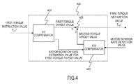
- FIG. 4 is an example of a control block diagram for performing processing that sets a final torque instruction value Tm2*.
- a vibration suppression control computation unit 400 that sets the final torque instruction value Tm2* includes a feedforward compensator 401 (hereinafter referred to as an "F/F compensator 401”), a feedback compensator 402 (hereinafter referred to as an "F/B compensator 402”) and an adder 403.
- F/F compensator 401 feedforward compensator
- F/B compensator 402 feedback compensator 402
- adder 403 an adder 403.
- the F/F compensator 401 inputs the first torque instruction value Tm1*, and outputs a first torque target value and a motor rotation rate estimation value for the first torque target value.
- the F/B compensator 402 inputs the motor rotation rate estimation value for the first torque target value and a motor rotation rate detection value, and outputs a second torque target value.
- the adder 403 adds the first torque target value output from the F/F compensator 401 and the second torque target value output from the F/B compensator 402, and outputs the final torque instruction value Tm2*.
- Fig. 5 is a block diagram showing the detailed configuration of the F/F compensator 401.
- the F/F compensator 401 includes: a vehicle model 501 that is formed with vehicle parameters and a dead zone model simulating a gear backlash; a drive shaft torsional angular velocity F/B model 502 that subtracts, from the torque instruction value, a value obtained by multiplying a feedback gain (F/B gain) to a pseudo torsional angular velocity; and control system lag elements 503.
- a value by summing an F/B gain K FB1 is subtracted from the first torque instruction value Tm1*, a value obtained by the subtraction is set as the drive shaft torsional angular velocity F/B instruction value T FB and this value is assumed to be the first torque target value.
- the vehicle model 501 will first be described.
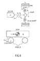
- Fig. 6 is a diagram of a modeled drive force transmission system of the vehicle, and the motion equation of the vehicle is expressed by formulas (1) to (6).
- Hw(s) in formula (24) can be expressed by formulas (25) to (29).
- H w s v 1 ⁇ s + v 0 w 1 ⁇ s + w 0
- the configuration of the vehicle model 501 shown in Fig. 5 is based on the above description.
- the drive shaft torsional angular velocity F/B model 502 will then be described.
- Formula (31) can be expressed by formula (32) from formulas (4) and (6).
- T FB K FB ⁇ 1 ⁇ s K d ⁇ T d
- the motor response lag Ga(s) is expressed by formula (40) below.
- the motor response lag is a time until a motor torque is actually generated for the final torque target value.
- ⁇ a is a motor response time constant.
- the F/B compensator 402 is preferably provided, motor torque control can be performed based on the first torque target value output from the F/F compensator 401 without provision of the F/B compensator 402.
- the F/F compensator 401 that inputs the motor torque instruction value and that computes the first torque target value by feedforward computation and the electric motor controller 2 (motor torque control unit) that controls the motor torque according to the first torque target value are provided.
- the F/F compensator 401 includes: the vehicle model 501 that inputs the motor torque instruction value to model the characteristic from the motor torque to the drive shaft torsional angular velocity; and the drive shaft torsional angular velocity feedback model 502 that feeds back the drive shaft torsional angular velocity output from the vehicle model 501 to the motor torque instruction value and that thereby computes the first torque target value.
- the drive shaft torsional angular velocity feedback model 502 since it is not necessary to set the gain of the drive shaft torsional angular velocity feedback model 502 low with consideration given to safety, it can be set at a feedback gain that satisfies vibration suppression performance.
- the first torque target value which is a feedforward compensation value, it is possible to reduce drive shaft torsional vibrations.
- the drive force transmission system of the vehicle model has a dead zone where the motor torque is not transmitted to the drive shaft torque of the vehicle, can simulate the gear backlash characteristic and can reduce drive shaft torsional angular vibrations even when the gear backlash is generated.
- the backlash characteristic can be realized without the amounts of backlash of a plurality of gears being set individually.
- the F/F compensator 401 performs, on the motor torque instruction value, lag processing corresponding to the lag elements included in the control system, and then performs the feedforward computation, it is possible to perform appropriate control with consideration given to the lag elements included in the control system.
- the lag elements included in the control system include at least one of a time lag caused by detecting the motor rotation rate which is a vehicle state amount and performing predetermined processing, a time lag necessary for calculating the final torque target value after the input of the motor torque instruction value and a time lag until the motor torque is actually produced for the final torque target value, it is possible to perform more appropriate control by performing the lag processing based on the lag elements actually produced.
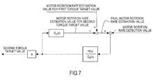
- the vehicle model is obtained by inputting a target torque instruction value and modeling a characteristic from the motor torque to the drive shaft torsional angular velocity and a characteristic from the motor torque to the motor rotation rate, and the F/B compensator 402 performs feedback computation based on the motor rotation rate estimation value and the motor rotation rate detection value output from the vehicle model 501, and thereby computes the second torque target value.
- the electric motor controller 2 controls the motor torque according to the final torque target value obtained by adding the first torque target value output from the F/F compensator 401 and the second torque target value output from the F/B compensator 402. In this way, even if a disturbance or a model error is produced, it is possible to reduce drive shaft torsional vibrations.
- Fig. 8 is an example of a control block diagram for performing, in a second embodiment, processing that sets the final torque instruction value Tm2*.
- a vibration suppression control computation unit 400A that sets the final torque instruction value Tm2* includes an F/F compensator 401A, an F/B compensator 402A and the adder 403.
- the F/F compensator 401A has a configuration that is obtained by omitting the control system lag elements 503 from the configuration of the F/F compensator 401 shown in Fig. 5 .
- the F/F compensator 401A includes: the vehicle model 501 that is formed with vehicle parameters and a dead zone model simulating a gear backlash; and the drive shaft torsional angular velocity F/B model 502 that subtracts, from the torque instruction value, a value obtained by multiplying the pseudo torsional angular velocity by the F/B gain, and sets the output of the drive shaft torsional angular velocity F/B model 502 at the first torque target value.
- the F/B compensator 402A is obtained by adding a control block consisting of the control computation time lag e -L1s , the sensor signal processing time lag e -L2s and the motor response lag Ga(s) constituting control system lag elements to the configuration of the F/B compensator 402 shown in Fig. 7 .
- the F/B compensator 402A adds the motor rotation rate estimation value for the second torque target value calculated by inputting the second torque target value and using the transmission characteristic Gp(s) which is a control target and the motor rotation rate estimation value for the first torque target value calculated from the vehicle model 501 of the F/F compensator 401A, and thereby calculates the final motor rotation rate estimation value.
- Fig. 9 is an example of a control block diagram for performing, in a third embodiment, processing that sets the final torque instruction value Tm2*.
- a vibration suppression control computation unit 400B that sets the final torque instruction value Tm2* includes the F/F compensator 401A, an F/B compensator 402B and the adder 403.
- a deviation between the final motor rotation rate estimation value calculated and the motor rotation rate detection value is passed through the filter H(s)/Gp(s) formed with the inverse characteristic of the transmission characteristic Gp(s) which is a control target and the bandpass filter H(s), and the second torque target value is calculated.
- the F/B compensator 402B performs, on the motor rotation rate estimation value, the lag processing corresponding to the lag elements included in the control system, performs the feedback computation based on the motor rotation rate estimation value on which the lag processing has been performed and the motor rotation rate detection value, and thereby computes the second torque target value, with the result that it is possible to perform appropriate feedback control with consideration given to the lag elements included in the control system.
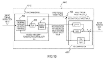
- the F/F compensator 401C is obtained by adding a control block 505 having the transmission characteristic of the motor response lag Ga(s) to the configuration of the F/F compensator 401A shown in Fig. 9 .
- the F/ F compensator 401 C includes: the vehicle model 501 that is formed with vehicle parameters and a dead zone model simulating a gear backlash; the drive shaft torsional angular velocity F/B model 502 that subtracts, from the torque instruction value, a value obtained by multiplying the pseudo torsional angular velocity by the F/B gain; and the control block 505 having the transmission characteristic of the motor response lag Ga(s) which is the lag element included in the control system, and sets the output of the drive shaft torsional angular velocity F/B model 502 at the first torque target value.
- the control block 505 is provided between the torsional angular velocity F/B model 502 and the vehicle model 501.
- the F/B compensator 402C adds a value obtained by passing the motor rotation rate estimation value for the first torque target value calculated by the vehicle model 501 of the F/F compensator 401C through each of the control block consisting of the control computation time lag e -L1s and the sensor signal processing time lag e -L2s and the motor rotation rate estimation value for the second torque target value calculated by inputting the second torque target value and using the transmission characteristic Gp(s) which is a control target, and thereby calculates the final motor rotation rate estimation value.
- a deviation between the final motor rotation rate estimation value and the motor rotation rate detection value calculated is passed through the filter H(s)/Gp(s) formed with the inverse characteristic of the transmission characteristic Gp(s) which is a control target and the bandpass filter H(s), and the second torque target value is calculated.
- Gp(s) which is a control target and the bandpass filter H(s)
- the F/B compensator 402C performs, on the motor rotation rate estimation value, the lag processing corresponding to the lag elements included in the control system, performs the feedback computation based on the motor rotation rate estimation value and the motor rotation rate detection value on which the lag processing has been performed and thereby computes the second torque target value, with the result that it is possible to perform appropriate feedback control with consideration given to the lag elements included in the control system.
- the device for controlling the electric vehicle according to the first embodiment even when the gain K of the F/B compensator 402 is set so as to acquire the same stability margin, since it is possible to prevent almost all of torsional vibrations by the feedforward compensation, it is possible to obtain a smooth response without the shock shown in Fig. 11 .
- the device for controlling the electric vehicle according to the second to fourth embodiments even when the gain of the F/B compensator 402 is added so as to acquire the stability margin, it is possible to obtain a smooth response without the shock shown in Fig. 11 .
Landscapes
- Engineering & Computer Science (AREA)
- Power Engineering (AREA)
- Transportation (AREA)
- Mechanical Engineering (AREA)
- Life Sciences & Earth Sciences (AREA)
- Sustainable Development (AREA)
- Sustainable Energy (AREA)
- Electric Propulsion And Braking For Vehicles (AREA)
Applications Claiming Priority (2)
| Application Number | Priority Date | Filing Date | Title |
|---|---|---|---|
| JP2012094722 | 2012-04-18 | ||
| PCT/JP2013/056295 WO2013157315A1 (ja) | 2012-04-18 | 2013-03-07 | 電動車両の制御装置および電動車両の制御方法 |
Publications (3)
| Publication Number | Publication Date |
|---|---|
| EP2839983A1 true EP2839983A1 (de) | 2015-02-25 |
| EP2839983A4 EP2839983A4 (de) | 2016-03-23 |
| EP2839983B1 EP2839983B1 (de) | 2020-11-25 |
Family
ID=49383283
Family Applications (1)
| Application Number | Title | Priority Date | Filing Date |
|---|---|---|---|
| EP13777556.5A Active EP2839983B1 (de) | 2012-04-18 | 2013-03-07 | Steuerungsvorrichtung für ein elektrofahrzeug und steuerungsverfahren für ein elektrofahrzeug |
Country Status (5)
| Country | Link |
|---|---|
| US (1) | US9315114B2 (de) |
| EP (1) | EP2839983B1 (de) |
| JP (1) | JP5900609B2 (de) |
| CN (1) | CN104245408B (de) |
| WO (1) | WO2013157315A1 (de) |
Cited By (4)
| Publication number | Priority date | Publication date | Assignee | Title |
|---|---|---|---|---|
| DE102015118759A1 (de) | 2015-11-02 | 2017-05-04 | Gkn Driveline International Gmbh | Verfahren zur Steuerung eines Antriebsmoments und Antriebsstranganordnung zur Durchführung des Verfahrens |
| CN109560730A (zh) * | 2017-09-26 | 2019-04-02 | 操纵技术Ip控股公司 | 永磁dc马达的前馈控制 |
| DE102017128113A1 (de) * | 2017-11-28 | 2019-05-29 | Gkn Automotive Ltd. | Verfahren zur Steuerung eines Antriebssystems für mindestens eine Achse eines Kraftfahrzeuges |
| EP3715963A1 (de) * | 2019-03-26 | 2020-09-30 | Sinfonia Technology Co., Ltd. | Totzeit-schätzvorrichtung und testvorrichtung damit |
Families Citing this family (25)
| Publication number | Priority date | Publication date | Assignee | Title |
|---|---|---|---|---|
| JP6330820B2 (ja) * | 2013-12-02 | 2018-05-30 | 日産自動車株式会社 | 電動車両の制御装置および電動車両の制御方法 |
| CN104071031B (zh) * | 2013-12-30 | 2019-04-23 | 上海大郡动力控制技术有限公司 | 一种纯电动汽车起步抖动的抑制方法 |
| JP6243279B2 (ja) * | 2014-04-02 | 2017-12-06 | カルソニックカンセイ株式会社 | 電動車両の駆動力制御装置 |
| WO2016021059A1 (ja) * | 2014-08-08 | 2016-02-11 | 日産自動車株式会社 | 電動車両の制御装置および電動車両の制御方法 |
| WO2016120978A1 (ja) | 2015-01-26 | 2016-08-04 | 日産自動車株式会社 | 電動車両の制御装置および電動車両の制御方法 |
| CN107428335B (zh) * | 2015-04-17 | 2020-04-21 | 三菱电机株式会社 | 混动车辆的控制装置及混动车辆的控制方法 |
| JP6641784B2 (ja) * | 2015-08-24 | 2020-02-05 | 日産自動車株式会社 | 電動車両の制御方法、及び、制御装置 |
| JP6597174B2 (ja) * | 2015-10-23 | 2019-10-30 | 日産自動車株式会社 | 電動車両の制御装置、及び、電動車両の制御方法 |
| JP6728633B2 (ja) * | 2015-10-30 | 2020-07-22 | 日産自動車株式会社 | 電動車両の制御方法、及び、制御装置 |
| US9809130B2 (en) * | 2015-11-12 | 2017-11-07 | GM Global Technology Operations LLC | Vehicle speed control systems and methods |
| BR112018071295B1 (pt) * | 2016-04-19 | 2023-01-17 | Nissan Motor Co., Ltd. | Método de controle para veículo elétrico e dispositivo de controle para veículo elétrico |
| JP6720714B2 (ja) * | 2016-06-16 | 2020-07-08 | 日産自動車株式会社 | 電動車両の制御方法、及び電動車両の制御装置 |
| WO2018020679A1 (ja) * | 2016-07-29 | 2018-02-01 | 日産自動車株式会社 | 車両の制御方法および制御装置 |
| JP6791377B2 (ja) * | 2017-06-01 | 2020-11-25 | 日産自動車株式会社 | 電動車両の制御方法、及び、制御装置 |
| KR102383373B1 (ko) * | 2017-11-21 | 2022-04-05 | 현대자동차주식회사 | 친환경 차량의 레졸버 옵셋 보정 장치 및 방법 |
| US10843575B2 (en) | 2017-11-30 | 2020-11-24 | Caterpillar Inc. | Control system for controlling operation of a drive motor |
| EP3726686A4 (de) * | 2017-12-11 | 2021-10-06 | Toshiba Mitsubishi-Electric Industrial Systems Corporation | Stromumwandlungsvorrichtung |
| JP7155674B2 (ja) * | 2018-07-04 | 2022-10-19 | 日産自動車株式会社 | 電動車両の制御方法、及び、制御装置 |
| JP7215371B2 (ja) * | 2019-08-01 | 2023-01-31 | トヨタ自動車株式会社 | 電動車両システム及び電動車両の制御方法 |
| US12065126B2 (en) | 2019-12-18 | 2024-08-20 | United States Department Of Energy | Supervisory genset control in range-extended electric vehicle |
| JP7491085B2 (ja) * | 2020-06-25 | 2024-05-28 | 三菱自動車工業株式会社 | 電動車両の制御装置 |
| WO2022044300A1 (ja) * | 2020-08-28 | 2022-03-03 | 日産自動車株式会社 | 電動機の制御方法及び電動機システム |
| JP7707855B2 (ja) * | 2021-10-22 | 2025-07-15 | 日産自動車株式会社 | 電動車両の制御方法及び制御装置 |
| JP7779330B2 (ja) * | 2022-01-18 | 2025-12-03 | 日産自動車株式会社 | 電動車両制御方法及び電動車両制御装置 |
| US20230303214A1 (en) * | 2022-02-14 | 2023-09-28 | Taiga Motors Inc. | Electric vehicle |
Family Cites Families (17)
| Publication number | Priority date | Publication date | Assignee | Title |
|---|---|---|---|---|
| US5495158A (en) * | 1994-09-30 | 1996-02-27 | Allen-Bradley Company, Inc. | Apparatus and method used with AC motors for controlling motor operation |
| JP2000217209A (ja) * | 1999-01-22 | 2000-08-04 | Toyota Motor Corp | 電動機を駆動力源とした車両の制振装置 |
| JP3775562B2 (ja) * | 2000-03-07 | 2006-05-17 | ジヤトコ株式会社 | パラレルハイブリッド車両 |
| JP3863719B2 (ja) | 2000-11-14 | 2006-12-27 | 株式会社豊田中央研究所 | 電気自動車の制御装置および制御方法 |
| JP3508742B2 (ja) | 2001-06-18 | 2004-03-22 | 日産自動車株式会社 | 電動モータを用いた車両の制振制御装置 |
| JP4419625B2 (ja) * | 2004-03-19 | 2010-02-24 | 日産自動車株式会社 | 車両用制振制御装置および車両用制振制御方法 |
| EP1619063B1 (de) * | 2004-07-21 | 2009-10-14 | Nissan Motor Company, Limited | Verfahren und Vorrichtung zum Steuern des Drehmoments eines Elektromotors für ein Kraftfahrzeug |
| JP4026630B2 (ja) * | 2004-08-03 | 2007-12-26 | 日産自動車株式会社 | 車両のモータトルク制御装置 |
| JP4752234B2 (ja) * | 2004-10-01 | 2011-08-17 | 日産自動車株式会社 | 車両の制動力制御装置 |
| JP4582168B2 (ja) * | 2008-03-21 | 2010-11-17 | 株式会社デンソー | 回転機の制御装置、及び回転機の制御システム |
| JP5218152B2 (ja) * | 2009-02-26 | 2013-06-26 | 日産自動車株式会社 | 電動車両の制御装置 |
| JP5035271B2 (ja) * | 2009-02-27 | 2012-09-26 | 日産自動車株式会社 | 電動車両の制振制御装置 |
| JP5228996B2 (ja) * | 2009-02-27 | 2013-07-03 | 日産自動車株式会社 | 電動車両の制振制御装置 |
| JP5381877B2 (ja) * | 2010-04-06 | 2014-01-08 | トヨタ自動車株式会社 | 車両制御装置 |
| JP5573456B2 (ja) * | 2010-07-23 | 2014-08-20 | 日産自動車株式会社 | 電動車両の制振制御装置および電動車両の制振制御方法 |
| JP5861554B2 (ja) * | 2012-04-18 | 2016-02-16 | 日産自動車株式会社 | 車両用制振制御装置 |
| KR101371475B1 (ko) * | 2012-10-31 | 2014-03-10 | 기아자동차주식회사 | 하이브리드 차량의 충전 제어 방법 및 시스템 |
-
2013
- 2013-03-07 JP JP2014511138A patent/JP5900609B2/ja active Active
- 2013-03-07 CN CN201380020542.9A patent/CN104245408B/zh active Active
- 2013-03-07 EP EP13777556.5A patent/EP2839983B1/de active Active
- 2013-03-07 US US14/394,957 patent/US9315114B2/en active Active
- 2013-03-07 WO PCT/JP2013/056295 patent/WO2013157315A1/ja not_active Ceased
Cited By (10)
| Publication number | Priority date | Publication date | Assignee | Title |
|---|---|---|---|---|
| DE102015118759A1 (de) | 2015-11-02 | 2017-05-04 | Gkn Driveline International Gmbh | Verfahren zur Steuerung eines Antriebsmoments und Antriebsstranganordnung zur Durchführung des Verfahrens |
| WO2017076862A1 (de) | 2015-11-02 | 2017-05-11 | Gkn Driveline International Gmbh | Verfahren zur steuerung eines antriebsmoments und antriebsstranganordnung zur durchführung des verfahrens |
| US10227070B2 (en) | 2015-11-02 | 2019-03-12 | Gkn Automotive Ltd. | Driveline torque control |
| CN109560730A (zh) * | 2017-09-26 | 2019-04-02 | 操纵技术Ip控股公司 | 永磁dc马达的前馈控制 |
| CN109560730B (zh) * | 2017-09-26 | 2022-05-13 | 操纵技术Ip控股公司 | 永磁dc马达的前馈控制 |
| DE102017128113A1 (de) * | 2017-11-28 | 2019-05-29 | Gkn Automotive Ltd. | Verfahren zur Steuerung eines Antriebssystems für mindestens eine Achse eines Kraftfahrzeuges |
| US10696176B2 (en) | 2017-11-28 | 2020-06-30 | Gkn Automotive Ltd. | Controlling a drive system for at least one axle of a motor vehicle |
| DE102017128113B4 (de) | 2017-11-28 | 2023-12-28 | Gkn Automotive Ltd. | Verfahren zur Steuerung eines Antriebssystems für mindestens eine Achse eines Kraftfahrzeuges |
| EP3715963A1 (de) * | 2019-03-26 | 2020-09-30 | Sinfonia Technology Co., Ltd. | Totzeit-schätzvorrichtung und testvorrichtung damit |
| US11366432B2 (en) | 2019-03-26 | 2022-06-21 | Sinfonia Technology Co., Ltd. | Dead time estimation device and test device including the same |
Also Published As
| Publication number | Publication date |
|---|---|
| CN104245408B (zh) | 2017-04-12 |
| JP5900609B2 (ja) | 2016-04-06 |
| EP2839983B1 (de) | 2020-11-25 |
| US9315114B2 (en) | 2016-04-19 |
| CN104245408A (zh) | 2014-12-24 |
| US20150112532A1 (en) | 2015-04-23 |
| EP2839983A4 (de) | 2016-03-23 |
| WO2013157315A1 (ja) | 2013-10-24 |
| JPWO2013157315A1 (ja) | 2015-12-21 |
Similar Documents
| Publication | Publication Date | Title |
|---|---|---|
| EP2839983B1 (de) | Steuerungsvorrichtung für ein elektrofahrzeug und steuerungsverfahren für ein elektrofahrzeug | |
| EP3446914B1 (de) | Steuerungsverfahren für elektrofahrzeug und steuerungsvorrichtung zur elektrofahrzeug | |
| EP3798044B1 (de) | Steuerungsvorrichtung für ein elektromotorfahrzeug und steuerungsverfahren für ein elektromotorfahrzeug | |
| EP3575132B1 (de) | Elektrofahrzeugsteuerungsverfahren und -steuerungsvorrichtung | |
| EP2815914A1 (de) | Schwingungsunterdrückungssteuervorrichtung für elektromotorfahrzeug und verfahren zur steuerung der schwingungsunterdrückung | |
| JP5862436B2 (ja) | 電動車両の制御装置 | |
| EP3251887B1 (de) | Steuerungsvorrichtung für ein elektrofahrzeug und steuerungsverfahren für ein elektrofahrzeug | |
| US11027617B2 (en) | Control method for electrically driven vehicle and control device for electrically driven vehicle | |
| RU2670563C1 (ru) | Устройство управления для электромоторного транспортного средства и способ управления для электромоторного транспортного средства | |
| US9621092B2 (en) | Induction motor control apparatus and induction motor control method | |
| US11878592B2 (en) | Control method for electric vehicle and control device for electric vehicle | |
| EP3492305A1 (de) | Fahrzeugsteuerungsverfahren und -steuerungsvorrichtung | |
| EP2940858B1 (de) | Motorsteuerungsvorrichtung und motorsteuerungsverfahren | |
| JP6597174B2 (ja) | 電動車両の制御装置、及び、電動車両の制御方法 | |
| JP2015043669A (ja) | 電動車両のモータ制振制御装置 | |
| JP7779176B2 (ja) | 電動車両の制御方法、及び電動車両の制御装置 | |
| JP2015023623A (ja) | 電動車両の制御装置および電動車両の制御方法 |
Legal Events
| Date | Code | Title | Description |
|---|---|---|---|
| PUAI | Public reference made under article 153(3) epc to a published international application that has entered the european phase |
Free format text: ORIGINAL CODE: 0009012 |
|
| 17P | Request for examination filed |
Effective date: 20141028 |
|
| AK | Designated contracting states |
Kind code of ref document: A1 Designated state(s): AL AT BE BG CH CY CZ DE DK EE ES FI FR GB GR HR HU IE IS IT LI LT LU LV MC MK MT NL NO PL PT RO RS SE SI SK SM TR |
|
| AX | Request for extension of the european patent |
Extension state: BA ME |
|
| DAX | Request for extension of the european patent (deleted) | ||
| RA4 | Supplementary search report drawn up and despatched (corrected) |
Effective date: 20160218 |
|
| RIC1 | Information provided on ipc code assigned before grant |
Ipc: B60L 3/00 20060101ALI20160212BHEP Ipc: B60L 15/20 20060101AFI20160212BHEP |
|
| GRAP | Despatch of communication of intention to grant a patent |
Free format text: ORIGINAL CODE: EPIDOSNIGR1 |
|
| STAA | Information on the status of an ep patent application or granted ep patent |
Free format text: STATUS: GRANT OF PATENT IS INTENDED |
|
| INTG | Intention to grant announced |
Effective date: 20200910 |
|
| GRAS | Grant fee paid |
Free format text: ORIGINAL CODE: EPIDOSNIGR3 |
|
| GRAA | (expected) grant |
Free format text: ORIGINAL CODE: 0009210 |
|
| STAA | Information on the status of an ep patent application or granted ep patent |
Free format text: STATUS: THE PATENT HAS BEEN GRANTED |
|
| RAP1 | Party data changed (applicant data changed or rights of an application transferred) |
Owner name: NISSAN MOTOR CO., LTD. |
|
| RIN1 | Information on inventor provided before grant (corrected) |
Inventor name: ITOU, KEN Inventor name: OONO, SHOU |
|
| AK | Designated contracting states |
Kind code of ref document: B1 Designated state(s): AL AT BE BG CH CY CZ DE DK EE ES FI FR GB GR HR HU IE IS IT LI LT LU LV MC MK MT NL NO PL PT RO RS SE SI SK SM TR |
|
| REG | Reference to a national code |
Ref country code: GB Ref legal event code: FG4D |
|
| REG | Reference to a national code |
Ref country code: CH Ref legal event code: EP |
|
| REG | Reference to a national code |
Ref country code: DE Ref legal event code: R096 Ref document number: 602013074315 Country of ref document: DE |
|
| REG | Reference to a national code |
Ref country code: AT Ref legal event code: REF Ref document number: 1337907 Country of ref document: AT Kind code of ref document: T Effective date: 20201215 |
|
| REG | Reference to a national code |
Ref country code: IE Ref legal event code: FG4D |
|
| REG | Reference to a national code |
Ref country code: AT Ref legal event code: MK05 Ref document number: 1337907 Country of ref document: AT Kind code of ref document: T Effective date: 20201125 |
|
| REG | Reference to a national code |
Ref country code: NL Ref legal event code: MP Effective date: 20201125 |
|
| PG25 | Lapsed in a contracting state [announced via postgrant information from national office to epo] |
Ref country code: PT Free format text: LAPSE BECAUSE OF FAILURE TO SUBMIT A TRANSLATION OF THE DESCRIPTION OR TO PAY THE FEE WITHIN THE PRESCRIBED TIME-LIMIT Effective date: 20210325 Ref country code: NO Free format text: LAPSE BECAUSE OF FAILURE TO SUBMIT A TRANSLATION OF THE DESCRIPTION OR TO PAY THE FEE WITHIN THE PRESCRIBED TIME-LIMIT Effective date: 20210225 Ref country code: FI Free format text: LAPSE BECAUSE OF FAILURE TO SUBMIT A TRANSLATION OF THE DESCRIPTION OR TO PAY THE FEE WITHIN THE PRESCRIBED TIME-LIMIT Effective date: 20201125 Ref country code: RS Free format text: LAPSE BECAUSE OF FAILURE TO SUBMIT A TRANSLATION OF THE DESCRIPTION OR TO PAY THE FEE WITHIN THE PRESCRIBED TIME-LIMIT Effective date: 20201125 Ref country code: GR Free format text: LAPSE BECAUSE OF FAILURE TO SUBMIT A TRANSLATION OF THE DESCRIPTION OR TO PAY THE FEE WITHIN THE PRESCRIBED TIME-LIMIT Effective date: 20210226 |
|
| PG25 | Lapsed in a contracting state [announced via postgrant information from national office to epo] |
Ref country code: IS Free format text: LAPSE BECAUSE OF FAILURE TO SUBMIT A TRANSLATION OF THE DESCRIPTION OR TO PAY THE FEE WITHIN THE PRESCRIBED TIME-LIMIT Effective date: 20210325 Ref country code: PL Free format text: LAPSE BECAUSE OF FAILURE TO SUBMIT A TRANSLATION OF THE DESCRIPTION OR TO PAY THE FEE WITHIN THE PRESCRIBED TIME-LIMIT Effective date: 20201125 Ref country code: LV Free format text: LAPSE BECAUSE OF FAILURE TO SUBMIT A TRANSLATION OF THE DESCRIPTION OR TO PAY THE FEE WITHIN THE PRESCRIBED TIME-LIMIT Effective date: 20201125 Ref country code: SE Free format text: LAPSE BECAUSE OF FAILURE TO SUBMIT A TRANSLATION OF THE DESCRIPTION OR TO PAY THE FEE WITHIN THE PRESCRIBED TIME-LIMIT Effective date: 20201125 Ref country code: AT Free format text: LAPSE BECAUSE OF FAILURE TO SUBMIT A TRANSLATION OF THE DESCRIPTION OR TO PAY THE FEE WITHIN THE PRESCRIBED TIME-LIMIT Effective date: 20201125 Ref country code: BG Free format text: LAPSE BECAUSE OF FAILURE TO SUBMIT A TRANSLATION OF THE DESCRIPTION OR TO PAY THE FEE WITHIN THE PRESCRIBED TIME-LIMIT Effective date: 20210225 |
|
| REG | Reference to a national code |
Ref country code: LT Ref legal event code: MG9D |
|
| PG25 | Lapsed in a contracting state [announced via postgrant information from national office to epo] |
Ref country code: HR Free format text: LAPSE BECAUSE OF FAILURE TO SUBMIT A TRANSLATION OF THE DESCRIPTION OR TO PAY THE FEE WITHIN THE PRESCRIBED TIME-LIMIT Effective date: 20201125 |
|
| PG25 | Lapsed in a contracting state [announced via postgrant information from national office to epo] |
Ref country code: LT Free format text: LAPSE BECAUSE OF FAILURE TO SUBMIT A TRANSLATION OF THE DESCRIPTION OR TO PAY THE FEE WITHIN THE PRESCRIBED TIME-LIMIT Effective date: 20201125 Ref country code: SK Free format text: LAPSE BECAUSE OF FAILURE TO SUBMIT A TRANSLATION OF THE DESCRIPTION OR TO PAY THE FEE WITHIN THE PRESCRIBED TIME-LIMIT Effective date: 20201125 Ref country code: RO Free format text: LAPSE BECAUSE OF FAILURE TO SUBMIT A TRANSLATION OF THE DESCRIPTION OR TO PAY THE FEE WITHIN THE PRESCRIBED TIME-LIMIT Effective date: 20201125 Ref country code: CZ Free format text: LAPSE BECAUSE OF FAILURE TO SUBMIT A TRANSLATION OF THE DESCRIPTION OR TO PAY THE FEE WITHIN THE PRESCRIBED TIME-LIMIT Effective date: 20201125 Ref country code: EE Free format text: LAPSE BECAUSE OF FAILURE TO SUBMIT A TRANSLATION OF THE DESCRIPTION OR TO PAY THE FEE WITHIN THE PRESCRIBED TIME-LIMIT Effective date: 20201125 Ref country code: SM Free format text: LAPSE BECAUSE OF FAILURE TO SUBMIT A TRANSLATION OF THE DESCRIPTION OR TO PAY THE FEE WITHIN THE PRESCRIBED TIME-LIMIT Effective date: 20201125 |
|
| REG | Reference to a national code |
Ref country code: DE Ref legal event code: R097 Ref document number: 602013074315 Country of ref document: DE |
|
| PG25 | Lapsed in a contracting state [announced via postgrant information from national office to epo] |
Ref country code: DK Free format text: LAPSE BECAUSE OF FAILURE TO SUBMIT A TRANSLATION OF THE DESCRIPTION OR TO PAY THE FEE WITHIN THE PRESCRIBED TIME-LIMIT Effective date: 20201125 |
|
| PLBE | No opposition filed within time limit |
Free format text: ORIGINAL CODE: 0009261 |
|
| STAA | Information on the status of an ep patent application or granted ep patent |
Free format text: STATUS: NO OPPOSITION FILED WITHIN TIME LIMIT |
|
| PG25 | Lapsed in a contracting state [announced via postgrant information from national office to epo] |
Ref country code: NL Free format text: LAPSE BECAUSE OF FAILURE TO SUBMIT A TRANSLATION OF THE DESCRIPTION OR TO PAY THE FEE WITHIN THE PRESCRIBED TIME-LIMIT Effective date: 20201125 Ref country code: MC Free format text: LAPSE BECAUSE OF FAILURE TO SUBMIT A TRANSLATION OF THE DESCRIPTION OR TO PAY THE FEE WITHIN THE PRESCRIBED TIME-LIMIT Effective date: 20201125 Ref country code: AL Free format text: LAPSE BECAUSE OF FAILURE TO SUBMIT A TRANSLATION OF THE DESCRIPTION OR TO PAY THE FEE WITHIN THE PRESCRIBED TIME-LIMIT Effective date: 20201125 Ref country code: IT Free format text: LAPSE BECAUSE OF FAILURE TO SUBMIT A TRANSLATION OF THE DESCRIPTION OR TO PAY THE FEE WITHIN THE PRESCRIBED TIME-LIMIT Effective date: 20201125 |
|
| REG | Reference to a national code |
Ref country code: CH Ref legal event code: PL |
|
| 26N | No opposition filed |
Effective date: 20210826 |
|
| PG25 | Lapsed in a contracting state [announced via postgrant information from national office to epo] |
Ref country code: ES Free format text: LAPSE BECAUSE OF FAILURE TO SUBMIT A TRANSLATION OF THE DESCRIPTION OR TO PAY THE FEE WITHIN THE PRESCRIBED TIME-LIMIT Effective date: 20201125 Ref country code: SI Free format text: LAPSE BECAUSE OF FAILURE TO SUBMIT A TRANSLATION OF THE DESCRIPTION OR TO PAY THE FEE WITHIN THE PRESCRIBED TIME-LIMIT Effective date: 20201125 |
|
| REG | Reference to a national code |
Ref country code: BE Ref legal event code: MM Effective date: 20210331 |
|
| PG25 | Lapsed in a contracting state [announced via postgrant information from national office to epo] |
Ref country code: LI Free format text: LAPSE BECAUSE OF NON-PAYMENT OF DUE FEES Effective date: 20210331 Ref country code: LU Free format text: LAPSE BECAUSE OF NON-PAYMENT OF DUE FEES Effective date: 20210307 Ref country code: CH Free format text: LAPSE BECAUSE OF NON-PAYMENT OF DUE FEES Effective date: 20210331 Ref country code: IE Free format text: LAPSE BECAUSE OF NON-PAYMENT OF DUE FEES Effective date: 20210307 |
|
| PG25 | Lapsed in a contracting state [announced via postgrant information from national office to epo] |
Ref country code: IS Free format text: LAPSE BECAUSE OF FAILURE TO SUBMIT A TRANSLATION OF THE DESCRIPTION OR TO PAY THE FEE WITHIN THE PRESCRIBED TIME-LIMIT Effective date: 20210325 |
|
| PG25 | Lapsed in a contracting state [announced via postgrant information from national office to epo] |
Ref country code: BE Free format text: LAPSE BECAUSE OF NON-PAYMENT OF DUE FEES Effective date: 20210331 |
|
| PG25 | Lapsed in a contracting state [announced via postgrant information from national office to epo] |
Ref country code: HU Free format text: LAPSE BECAUSE OF FAILURE TO SUBMIT A TRANSLATION OF THE DESCRIPTION OR TO PAY THE FEE WITHIN THE PRESCRIBED TIME-LIMIT; INVALID AB INITIO Effective date: 20130307 |
|
| PG25 | Lapsed in a contracting state [announced via postgrant information from national office to epo] |
Ref country code: CY Free format text: LAPSE BECAUSE OF FAILURE TO SUBMIT A TRANSLATION OF THE DESCRIPTION OR TO PAY THE FEE WITHIN THE PRESCRIBED TIME-LIMIT Effective date: 20201125 |
|
| PG25 | Lapsed in a contracting state [announced via postgrant information from national office to epo] |
Ref country code: MK Free format text: LAPSE BECAUSE OF FAILURE TO SUBMIT A TRANSLATION OF THE DESCRIPTION OR TO PAY THE FEE WITHIN THE PRESCRIBED TIME-LIMIT Effective date: 20201125 |
|
| PG25 | Lapsed in a contracting state [announced via postgrant information from national office to epo] |
Ref country code: TR Free format text: LAPSE BECAUSE OF FAILURE TO SUBMIT A TRANSLATION OF THE DESCRIPTION OR TO PAY THE FEE WITHIN THE PRESCRIBED TIME-LIMIT Effective date: 20201125 |
|
| PG25 | Lapsed in a contracting state [announced via postgrant information from national office to epo] |
Ref country code: MT Free format text: LAPSE BECAUSE OF FAILURE TO SUBMIT A TRANSLATION OF THE DESCRIPTION OR TO PAY THE FEE WITHIN THE PRESCRIBED TIME-LIMIT Effective date: 20201125 |
|
| PGFP | Annual fee paid to national office [announced via postgrant information from national office to epo] |
Ref country code: GB Payment date: 20260219 Year of fee payment: 14 |
|
| PGFP | Annual fee paid to national office [announced via postgrant information from national office to epo] |
Ref country code: DE Payment date: 20260219 Year of fee payment: 14 |
|
| PGFP | Annual fee paid to national office [announced via postgrant information from national office to epo] |
Ref country code: FR Payment date: 20260220 Year of fee payment: 14 |