EP2839984B1 - Mécanisme d'inclinaison de siège et élément de collecte d'huile - Google Patents
Mécanisme d'inclinaison de siège et élément de collecte d'huile Download PDFInfo
- Publication number
- EP2839984B1 EP2839984B1 EP13805724.5A EP13805724A EP2839984B1 EP 2839984 B1 EP2839984 B1 EP 2839984B1 EP 13805724 A EP13805724 A EP 13805724A EP 2839984 B1 EP2839984 B1 EP 2839984B1
- Authority
- EP
- European Patent Office
- Prior art keywords
- oil collecting
- collecting element
- boss
- oil
- face
- Prior art date
- Legal status (The legal status is an assumption and is not a legal conclusion. Google has not performed a legal analysis and makes no representation as to the accuracy of the status listed.)
- Active
Links
Images



Classifications
-
- B—PERFORMING OPERATIONS; TRANSPORTING
- B60—VEHICLES IN GENERAL
- B60N—SEATS SPECIALLY ADAPTED FOR VEHICLES; VEHICLE PASSENGER ACCOMMODATION NOT OTHERWISE PROVIDED FOR
- B60N2/00—Seats specially adapted for vehicles; Arrangement or mounting of seats in vehicles
- B60N2/02—Seats specially adapted for vehicles; Arrangement or mounting of seats in vehicles the seat or part thereof being movable, e.g. adjustable
- B60N2/22—Seats specially adapted for vehicles; Arrangement or mounting of seats in vehicles the seat or part thereof being movable, e.g. adjustable the back-rest being adjustable
- B60N2/2213—Gear wheel driven mechanism
-
- B—PERFORMING OPERATIONS; TRANSPORTING
- B60—VEHICLES IN GENERAL
- B60N—SEATS SPECIALLY ADAPTED FOR VEHICLES; VEHICLE PASSENGER ACCOMMODATION NOT OTHERWISE PROVIDED FOR
- B60N2/00—Seats specially adapted for vehicles; Arrangement or mounting of seats in vehicles
- B60N2/02—Seats specially adapted for vehicles; Arrangement or mounting of seats in vehicles the seat or part thereof being movable, e.g. adjustable
- B60N2/22—Seats specially adapted for vehicles; Arrangement or mounting of seats in vehicles the seat or part thereof being movable, e.g. adjustable the back-rest being adjustable
- B60N2/225—Seats specially adapted for vehicles; Arrangement or mounting of seats in vehicles the seat or part thereof being movable, e.g. adjustable the back-rest being adjustable by cycloidal or planetary mechanisms
-
- B—PERFORMING OPERATIONS; TRANSPORTING
- B60—VEHICLES IN GENERAL
- B60N—SEATS SPECIALLY ADAPTED FOR VEHICLES; VEHICLE PASSENGER ACCOMMODATION NOT OTHERWISE PROVIDED FOR
- B60N2/00—Seats specially adapted for vehicles; Arrangement or mounting of seats in vehicles
- B60N2/02—Seats specially adapted for vehicles; Arrangement or mounting of seats in vehicles the seat or part thereof being movable, e.g. adjustable
- B60N2/22—Seats specially adapted for vehicles; Arrangement or mounting of seats in vehicles the seat or part thereof being movable, e.g. adjustable the back-rest being adjustable
- B60N2/225—Seats specially adapted for vehicles; Arrangement or mounting of seats in vehicles the seat or part thereof being movable, e.g. adjustable the back-rest being adjustable by cycloidal or planetary mechanisms
- B60N2/2252—Seats specially adapted for vehicles; Arrangement or mounting of seats in vehicles the seat or part thereof being movable, e.g. adjustable the back-rest being adjustable by cycloidal or planetary mechanisms in which the central axis of the gearing lies inside the periphery of an orbital gear, e.g. one gear without sun gear
-
- B—PERFORMING OPERATIONS; TRANSPORTING
- B60—VEHICLES IN GENERAL
- B60N—SEATS SPECIALLY ADAPTED FOR VEHICLES; VEHICLE PASSENGER ACCOMMODATION NOT OTHERWISE PROVIDED FOR
- B60N2/00—Seats specially adapted for vehicles; Arrangement or mounting of seats in vehicles
- B60N2/02—Seats specially adapted for vehicles; Arrangement or mounting of seats in vehicles the seat or part thereof being movable, e.g. adjustable
- B60N2/22—Seats specially adapted for vehicles; Arrangement or mounting of seats in vehicles the seat or part thereof being movable, e.g. adjustable the back-rest being adjustable
- B60N2/225—Seats specially adapted for vehicles; Arrangement or mounting of seats in vehicles the seat or part thereof being movable, e.g. adjustable the back-rest being adjustable by cycloidal or planetary mechanisms
- B60N2/2254—Seats specially adapted for vehicles; Arrangement or mounting of seats in vehicles the seat or part thereof being movable, e.g. adjustable the back-rest being adjustable by cycloidal or planetary mechanisms provided with braking systems
-
- F—MECHANICAL ENGINEERING; LIGHTING; HEATING; WEAPONS; BLASTING
- F16—ENGINEERING ELEMENTS AND UNITS; GENERAL MEASURES FOR PRODUCING AND MAINTAINING EFFECTIVE FUNCTIONING OF MACHINES OR INSTALLATIONS; THERMAL INSULATION IN GENERAL
- F16H—GEARING
- F16H57/00—General details of gearing
- F16H57/04—Features relating to lubrication or cooling or heating
- F16H57/042—Guidance of lubricant
- F16H57/0427—Guidance of lubricant on rotary parts, e.g. using baffles for collecting lubricant by centrifugal force
-
- F—MECHANICAL ENGINEERING; LIGHTING; HEATING; WEAPONS; BLASTING
- F16—ENGINEERING ELEMENTS AND UNITS; GENERAL MEASURES FOR PRODUCING AND MAINTAINING EFFECTIVE FUNCTIONING OF MACHINES OR INSTALLATIONS; THERMAL INSULATION IN GENERAL
- F16H—GEARING
- F16H57/00—General details of gearing
- F16H57/04—Features relating to lubrication or cooling or heating
- F16H57/048—Type of gearings to be lubricated, cooled or heated
- F16H57/0482—Gearings with gears having orbital motion
-
- F—MECHANICAL ENGINEERING; LIGHTING; HEATING; WEAPONS; BLASTING
- F16—ENGINEERING ELEMENTS AND UNITS; GENERAL MEASURES FOR PRODUCING AND MAINTAINING EFFECTIVE FUNCTIONING OF MACHINES OR INSTALLATIONS; THERMAL INSULATION IN GENERAL
- F16H—GEARING
- F16H57/00—General details of gearing
- F16H57/04—Features relating to lubrication or cooling or heating
- F16H57/048—Type of gearings to be lubricated, cooled or heated
- F16H57/0482—Gearings with gears having orbital motion
- F16H57/0486—Gearings with gears having orbital motion with fixed gear ratio
-
- B—PERFORMING OPERATIONS; TRANSPORTING
- B60—VEHICLES IN GENERAL
- B60N—SEATS SPECIALLY ADAPTED FOR VEHICLES; VEHICLE PASSENGER ACCOMMODATION NOT OTHERWISE PROVIDED FOR
- B60N2205/00—General mechanical or structural details
- B60N2205/20—Measures for elimination or compensation of play or backlash
-
- F—MECHANICAL ENGINEERING; LIGHTING; HEATING; WEAPONS; BLASTING
- F16—ENGINEERING ELEMENTS AND UNITS; GENERAL MEASURES FOR PRODUCING AND MAINTAINING EFFECTIVE FUNCTIONING OF MACHINES OR INSTALLATIONS; THERMAL INSULATION IN GENERAL
- F16H—GEARING
- F16H1/00—Toothed gearings for conveying rotary motion
- F16H1/28—Toothed gearings for conveying rotary motion with gears having orbital motion
- F16H1/32—Toothed gearings for conveying rotary motion with gears having orbital motion in which the central axis of the gearing lies inside the periphery of an orbital gear
Definitions
- the present application relates to the technical field of seat angle adjustment, and particularly relates to an oil collecting element for a seat recliner.
- the present application further relates to a seat recliner having the above oil collecting element.
- seat recliner there are generally two kinds of seat recliner.
- One kind of seat recliner is of a leaf-spring adjusting mechanism based on a principle of ratchet mechanism; and the other kind of seat recliner is of a gear adjusting mechanism based on a principle of planetary gear transmission.
- Fig. 1 is an external structural diagram of a seat in the prior art
- Fig. 2 is an assembly exploded view of a seat recliner in an embodiment in the prior art
- Fig. 3 is a structural simplified diagram of a gear transmission mechanism in the seat recliner as shown in Fig. 2 .
- a conventional seat recliner 00 is mounted between a seat back and a seat base, and generally implemented through a planetary gear transmission, as shown in Fig. 1 .
- the conventional seat recliner 00 includes an inner toothed plate 01 having an inner toothed rim, an outer toothed plate 02 having an outer toothed rim, an eccentric wheel 03, a wedge block 04, and a drive cam 05.
- the inner toothed plate 01 is adapted to be fixedly connected with the seat back, and the central portion of the inner toothed plate 01 is provided with a shaft shoulder 011.
- the outer toothed plate 02 is adapted to be fixedly connected with the seat base, and the central portion of the outer toothed plate 02 is provided with a central hole 021.
- the outer toothed rim is meshed with the inner toothed rim, and a radial eccentric area is formed between the shaft shoulder 011 and the central hole 021.
- the eccentric wheel 03 is placed in the radial eccentric area.
- the eccentric wheel 03, the inner toothed plate 01 and the outer toothed plate 02 constitute a planetary gear transmission mechanism with few tooth difference.
- the wedge block 04 is placed in the radial eccentric area, and under a circumferential force applied by an elastic member, the eccentric wheel 03 and the wedge block 04 eliminate gaps between the eccentric wheel 03 and the central hole 021 of the outer toothed plate 02 and between the meshed teeth.
- the drive cam 05 drives the eccentric wheel 03 or the wedge block 04, so as to enable a relative rotation between the inner toothed plate 01 and the outer toothed plate 02 by an angle.
- the eccentric wheel 03 and the central hole 021 of the outer toothed wheel 02, the eccentric wheel 03 and the shaft shoulder 011 of the inner toothed plate 01, the wedge block 04 and the central hole 021 of the outer toothed wheel 02, and the wedge block 04 and the shaft shoulder 011 of the inner toothed plate 01 constitute four friction pairs each undergoing three stages of oil lubrication, boundary friction and dry friction.
- the oil lubrication means the friction with lubricating oil between two friction surfaces.
- the boundary friction means that, there is lubricating oil between two friction surfaces, and an extremely thin boundary oil film is formed on the metal surface due to the absorption between the lubricating oil and the metal surface and has the thickness of less than 1 ⁇ m, which is not sufficient to separate two metal surfaces, so that the microcosmic peaks of the two metal surfaces will rub against each other while moving relative to each other.
- the dry friction means the friction without lubricating oil.
- each of the above friction pairs remains in oil lubrication and boundary friction.
- the lubricating oil between two components forming a friction pair are rolled to two ends of the friction surfaces, so that the friction between the friction pair will turn into the dry friction.
- the wear between the two components forming the friction pair is aggravated.
- a shaking gap will be formed between the seat recliner 00 and the seat, so that noise, shaking and so on may exist in operation, and therefore the comfort of the seat may be affected.
- the conventional seat recliner 00 fails to meet the requirement of users.
- An object of the present application is to provide an oil collecting element for a seat recliner, which is capable of re-collecting the lubricating oil between a friction pair inside the seat recliner to friction surfaces, so as to reduce the wear rate of the friction pair.
- Another object of the present application is to provide a seat recliner, in which inner friction pairs remain in states of oil lubrication and boundary friction all along with a slower wear rate.
- an oil collecting element for a seat recliner.
- the oil collecting element is adapted to be fixedly connected with one of components forming a friction pair in the seat recliner, and has an end face facing towards the other component in the friction pair.
- Each of two ends of the end face is provided with a boss, such as to form an oil collecting gap at the middle of the end face.
- a side face of the boss serves as an oil guiding face, and is configured to be gradually closer to the center of the oil collecting gap from outside to inside.
- the oil collecting element according to the present application is adapted to be fixedly connected to one component of a friction pair, and is provided with a boss at each of the two ends of the end face facing towards the other component in the friction pair, wherein an oil collecting gap is formed in the middle of the end face, a side face of the boss is configured to be gradually closer to the center of the oil collecting gap in a direction from outside to inside, and thus serves as an oil guiding face.
- the outer side of the side face of the boss firstly abuts against an end wall of the other component, so as to block the lubricating oil rolled to the two ends of the other component by the friction pair, and the blocked lubricating oil further flows towards the oil collecting gap along the oil guiding face (the side face of the boss), thereby lubricating the friction surfaces.
- the oil collecting gap of the oil collecting element acts as a dynamic oil passage of the lubricating oil, and collects the lubricating oil into the portion between the friction surfaces of the friction pair continuously, thereby effectively reducing the wear rate of the friction pair and prolonging the service life of the seat recliner.
- the boss located at each of the two ends is symmetrically configured with respect to a longitudinal centerline of the oil collecting element.
- the oil collecting gap located in the middle of the end face is also of a symmetrical structure, and the lubricating oil can be symmetrically distributed at two sides of the oil collecting element evenly, so as to evenly lubricate the friction surfaces at the two sides of the oil collecting element, thereby avoiding partial occurrence of the dry friction.
- the cross section of the boss is configured to be in a half circular shape.
- the cross section of the boss is configured to be in an isosceles trapezoidal shape.
- the cross section of the boss is configured to be in an isosceles triangular shape.
- the cross section may be varied, such as in a half circular shape, an isosceles trapezoidal shape, or an isosceles triangular shape, etc.
- the side face of the boss has a smooth transition in the direction from outside to inside, which facilitates guiding the lubricating oil to flow into the middle of the oil collecting gap, thereby enhancing the oil collecting effect.
- the oil collecting element is an elastic member.
- the elastic deformation of the oil collecting element will apply a pressing force to the other component in the friction pair, so as to scrape effectively the lubricating oil at the two ends of the other component, and then enable the lubricating oil to flow into the oil collecting gap at the middle of the oil collecting element.
- a friction pair is formed between two components of the seat recliner, and one component in the friction pair is fixedly connected with the oil collecting element described above.
- the seat recliner includes an inner toothed plate having a shaft shoulder, an outer toothed plate having a central hole, an eccentric wheel and a wedge block. Friction pairs are formed between the eccentric wheel and the outer surface of the shaft shoulder, between the eccentric wheel and the inner wall of the central hole, between the wedge block and the outer surface of the shaft shoulder, and between the wedge block and the inner wall of the central hole.
- the oil collecting element is provided with a connecting boss, and the eccentric wheel and the wedge block each are provided with a groove fixedly engaged with the connecting boss, so as to improve the reliability of the connection and the convenience of the detachment.
- the seat recliner according to the present application has the oil collecting element described above, the technical effects of the oil collecting element described above are applicable to the seat recliner according to the present application.
- An object of the present application is to provide a seat recliner in which inner friction pairs are always in states of oil lubrication and boundary friction with a slower wear rate.
- Another object of the present application is to provide an oil collecting element of a seat recliner, which is capable of re-collecting the lubricating oil between a friction pair inside the seat recliner to friction surfaces, so as to reduce the wear rate of the friction pair.
- Fig. 4 is an assembly exploded perspective view of a seat recliner in an embodiment according to the present application
- Fig. 5 is structural view of the seat recliner as shown in Figure 4 after assembled
- Fig. 6 is a sectional view of the seat recliner as shown in Fig. 5 taken along a direction A-A
- Fig. 7 is a sectional view of the seat recliner as shown in Fig. 5 taken along a direction B-B.
- the seat recliner includes an inner toothed plate 3, an outer toothed plate 4, an eccentric wheel 5 and a wedge block 6.
- the inner toothed plate 3 has an inner toothed rim 32, and a shaft shoulder 31 is provided in the central portion of the inner toothed plate 3.
- the outer toothed plate 4 has an outer toothed rim 42, and a central hole 41 is provided in the central portion of the outer toothed plate 4.
- the inner toothed plate 3 and the outer toothed plate 4 are engaged by the inner toothed rim 32 and the outer toothed rim 42, respectively.
- a radial eccentric area is formed between the shaft shoulder 31 and the central hole 41, and each of the eccentric wheel 5 and the wedge block 6 are internally disposed in the radial eccentric area.
- two friction pairs 2 are formed of an inner end face of the eccentric wheel 5 and the outer surface of the shaft shoulder 31, as well as an outer end face of the eccentric wheel 5 and the inner surface of the central hole 41, as shown in Fig. 6 .
- two friction pairs 2 are also formed of an inner end face of the wedge block 6 and the outer surface of the shaft shoulder 31, as well as an outer end face of the wedge block 6 and the inner surface of the central hole 41, as shown in Fig. 7 .
- the seat recliner according to the present application is further provided with an oil collecting element 1.
- the oil collecting element 1 is fixedly connected with one component in a friction pair 2, with its end face 11 (referring to Fig. 8 ) facing towards the other component in the friction pair 2.
- the end face 11 may be structurally configured such as to re-collect the lubricating oil, which has been rolled to the two ends of the friction surfaces by the friction pair 2, to the intermediate portion between the two friction surfaces, as shown in Figs. 6 and 7 .
- the oil collecting element 1 may be fixedly connected to either component of the friction pairs 2, and may be specifically connected to the inner wall of the central hole 41, the eccentric wheel 5, the wedge block 6 or the shaft shoulder 31.
- the friction pairs 2 are formed between the inner end face of the eccentric wheel 5 and the outer surface of the shaft shoulder 31, between the outer end face of the eccentric wheel 5 and the inner wall of the central hole 41, between the inner end face of the wedge block 6 and the outer surface of the shaft shoulder 31, and between the outer end face of the wedge block 6 and the inner wall of the central hole 41, the oil collecting element 1 only needs to be provided on one of the components in each friction pair 2, and does not need to be provided on both friction surfaces of the same friction pair 2.
- At least one oil collecting element 1 may be mounted on each of the inner and outer end faces of the eccentric wheel 5 and the wedge block 6. Then, the eccentric wheel 5 and the wedge block 6 may drive the oil collecting elements 1 to rotate as they rotates, and then act on the outer surface of the shaft shoulder 31 and the inner wall of the central hole 41 via the oil collecting members 1 so as to re-collect the lubricating oil circumferentially distributed on the shaft shoulder 31 and the inner wall of the central hole 41.
- the oil collecting element 1 may be provided on solely the eccentric wheel 5 or solely the wedge block 6 so that the lubricating oil is re-collected onto the outer surface of the shaft shoulder 31 or onto the inner wall of the central hole 41, that is, there is no need for providing the oil collecting element 1 on both the eccentric wheel 5 and the wedge block 6, thereby reducing the cost and simplifying the disassembly.
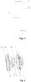
- Fig. 8 is a perspective structural view of an arrangement of an eccentric wheel according to the present application
- Fig. 9 is a cross sectional schematic view of a boss in the oil collecting element as shown in Fig. 8
- Fig. 10 is a schematic structural view of the eccentric wheel as shown in Fig. 8 mounted between an inner toothed plate and an outer toothed plate
- Fig. 11 is a schematic view of the working process of the oil collecting element according to the present application.
- a connecting boss 14 may be provided on the oil collecting element 1, and a groove engaged with the connecting boss 14 may be provided on each of the eccentric wheel 5 and the wedge block 6, so that the oil collecting element 1 is fixedly engaged via the connecting boss 14.
- the connecting boss 14 may be directly detached from the groove. It is to be appreciated by the person skilled in the art that, it is not limited to the connecting boss 14 and the groove, and any other detachable connecting means may also be adopted.
- the four friction pairs 2 described above are often found in a seat recliner. If there is another friction pair 2 in the seat recliner, the oil collecting element 1 may also be provided on this another friction pair 2, and may be configured similar to the above structure, so as to achieve the oil collecting effect and reduce the wear of the parts.
- the oil collecting element 1 is arranged on the eccentric wheel 5.
- the oil collecting element 1 may be arranged only on the eccentric wheel 5.
- the oil collecting element 1 may be provided on other friction components and may be configured with reference to the structure on the eccentric wheel 5.
- the oil collecting element 1 is fixedly connected with one component in a friction pair 2 of the seat recliner, and has an end face 11 facing towards the other component in the friction pair 2.
- Each of two ends of the end face 11 is provided with a boss 12, such as to form an oil collecting gap 13 at the middle of the end face 11.
- the side face of the boss 12 is an oil guiding face 121 configured to be gradually closer to the center of the oil collecting gap 13 in a direction from outside to inside.
- the faces of the two bosses 12 opposite to each other are respective side faces of the bosses, i.e., the oil guiding faces 121, as shown in Fig. 8 .
- the direction of the oil collecting element 1 parallel to the central axis of the seat recliner is a longitudinal direction of the oil collecting element 1.
- the side of the oil collecting element 1 adjacent to the longitudinal centerline M of the oil collecting element 1 is an inner side of the oil collecting element 1, and the direction from outside to inside means the direction orienting from the side away from the longitudinal centerline M of the oil collecting element 1 to the longitudinal centerline M of the oil collecting element 1.
- the end face of the boss 12 located above the longitudinal centerline M is defined as a top face
- the end face located below the longitudinal centerline M is defined as a bottom face.
- the line connecting the end points at the two sides of the oil guiding face 121 is taken as an X-axis
- the orientation of the rotation direction R being taken as a positive direction of the X-axis
- the line parallel to the longitudinal centerline M is taken as a Y-axis
- the direction from the down to up being taken as a positive direction of the Y-axis, as shown in Fig. 9 .
- the boss 12 located at an upper position along the Y-axis is defined as a first boss 122
- the boss 12 located at a lower position along the Y-axis is defined as a second boss 123.
- the first boss 122 is arranged upside-down.
- the vertical coordinates of points on the oil guiding face 121 of the first boss 122 are reduced first and then increased in the positive direction of the X-axis, and are symmetrically arranged with respect to the vertical line of the longitudinal centerline M. Since the first boss 122 is of an upside-down structure, the distances from the points on its oil guiding face 121 to the top face gradually increase.
- the vertical coordinates of points on the oil guiding face 121 of the second boss 123 are increased first and then reduced in the positive direction of the X-axis, and are symmetrically arranged with respect to the vertical line of the longitudinal centerline M.
- the oil collecting gap 13 between the first boss 122 and the second boss 123 is small at the middle portion and is large at the two ends, and thus the oil guiding faces 121 of the first boss 122 and the second boss 123 function as oil guiding faces capable of guiding the lubricating oil smoothly into the oil collecting gap 13 and enabling the lubricating oil to flow onto the friction surfaces through the oil collecting gap 13.
- the oil guiding face 121 is not limited to be configured in a half circular shape, a trapezoidal shape, or a triangular shape, so long as the oil guiding face 121 has a certain inclination facilitating the lubricating oil to be guided into the middle of the oil collecting gap 13 gradually.
- first boss 122 and the second boss 123 may also be of different structures.
- the cross section of the first boss 122 may be configured in a trapezoidal shape
- the cross section of the second boss 123 may be configured in a triangular shape or any other shape.
- the black portion represents lubricating oil 7
- the direction indicated by the arrow R is a rotation direction of the eccentric wheel 5 and the oil collecting element 1.
- the oil collecting element 1 arranged thereon rotates along with the eccentric wheel 5.
- the forward side along the rotation direction R of the oil guiding face 121 may firstly contact with the inner wall of the central hole 41 of the outer toothed plate 4, so as to scrape the lubricating oil 7 rolled to the two ends of the other component onto the oil guiding face 121.
- the oil collecting element 1 keeps rotating along the rotation direction R, though the lubricating oil 7 may keep rotating along with the oil guiding face 121 under the inertial force at a rotation speed smaller than the movement speed of the oil guiding face 121, the lubricating oil 7 gradually flows towards the oil collecting gap 13 at the middle of the end face 11 along the oil guiding face 121, thereby re-collecting the lubricating oil 7. Since the end face 11 is arranged towards the inner wall of the central hole 41, the lubricating oil 7 flowing into the oil collecting gap 13 is limited between the inner wall of the central hole 41 and the end face 11, so that the lubricating oil 7 re-adheres to the inner wall of the central hole 41.
- the outer end face of the eccentric wheel 5 re-contact with the inner wall of the central hole 41, and performs the relative movement with lubricating oil therebetween.
- the lubricating oil is rolled to the two ends, and after the oil collecting element 1 passes by, the lubricating oil is re-collected in the middle, so as to lubricate the friction surfaces.
- Fig. 12 is a perspective structural view of the oil collecting element in a first embodiment according to the present application
- Fig. 13 is a perspective structural view of the oil collecting element in a second embodiment according to the present application.
- the bosses 12 located at the two ends may be configured as a symmetrical structure, and each of the bosses 12 is configured to be a symmetrical structure with respect to the longitudinal centerline M of the oil collecting element 1.
- the longitudinal direction of the oil collecting element 1 is the direction parallel to the axis of the eccentric wheel 5.
- the longitudinal direction of the oil collecting element 1 includes the direction of its longitudinal centerline M and the direction parallel to the longitudinal centerline M.
- the direction perpendicular to the longitudinal centerline M in a horizontal plane is a transverse direction of the oil collecting element 1.
- the bosses 12 When the bosses 12 is arranged symmetrically about the longitudinal centerline M, the two sides of the oil guiding face 121 of the boss 12 have the same structure, and no matter whether the rotation direction R of the boss 12 is a clockwise or anti clockwise direction, the forward side of the oil guiding face 121 along the rotation direction R may scrape the lubricating oil 7, and then may collect the lubricating oil into the oil collecting gap 13 smoothly, which has a more broad application scope, and a more flexible and convenient operation.
- the lubricating oil flows into the oil collecting gap 13 from outside to inside along the oil guiding face 121 at substantially the same rate, so as to improve the evenness of the lubrication to the friction surfaces.
- the cross section of the boss 12 may be configured to be in a half circular shape, an isosceles trapezoidal shape or an isosceles triangular shape, as shown in Fig. 13 .
- the cross section of the boss 12 may be also arranged to be in a trapezoidal shape, a triangular shape and so on.
Landscapes
- Engineering & Computer Science (AREA)
- Mechanical Engineering (AREA)
- General Engineering & Computer Science (AREA)
- Aviation & Aerospace Engineering (AREA)
- Transportation (AREA)
- Chairs For Special Purposes, Such As Reclining Chairs (AREA)
- Seats For Vehicles (AREA)
- General Details Of Gearings (AREA)
Claims (9)
- Elément de collecte d'huile pour un dispositif d'inclinaison de siège, dans lequel l'élément de collecte d'huile (1) est adapté pour être connecté de manière fixe à l'un de composants formant une paire à friction (2) dans le dispositif d'inclinaison de siège, et a une face d'extrémité (11) faisant face à l'autre composant dans la paire à friction (2), chacune de deux extrémités de la face d'extrémité (11) est munie d'un bossage (12), de manière à former un espace de collecte d'huile (13) au niveau du milieu de la face d'extrémité (11) ; une face latérale du bossage (12) sert de face de guidage d'huile (121), et est configurée pour être graduellement plus proche du centre de l'espace de collecte d'huile (13) de l'extérieur à l'intérieur.
- Elément de collecte d'huile selon la revendication 1, dans lequel le bossage (12) situé à chacune des deux extrémités est configuré symétriquement par rapport à une ligne médiane longitudinale de l'élément de collecte d'huile (1).
- Elément de collecte d'huile selon la revendication 2, dans lequel la section transversale du bossage (12) est configurée pour être de forme semi-circulaire.
- Elément de collecte d'huile selon la revendication 2, dans lequel la section transversale du bossage (12) est configurée pour être de forme trapézoïdale isocèle.
- Elément de collecte d'huile selon la revendication 2, dans lequel la section transversale du bossage (12) est configurée pour être de forme triangulaire isocèle.
- Elément de collecte d'huile selon l'une quelconque des revendications 1 à 5, dans lequel l'élément de collecte d'huile (1) est un élément élastique.
- Dispositif d'inclinaison de siège, dans lequel une paire à friction (2) est formée entre deux composants, dans lequel un premier composant de la paire à friction (2) est relié de façon fixe à l'élément de collecte d'huile (1) selon l'une quelconque des revendications 1 à 6.
- Dispositif d'inclinaison de siège selon la revendication 7, comprenant une plaque dentée intérieure (3) avec un épaulement d'arbre (31), une plaque dentée extérieure (4) avec un trou central (41), une roue excentrique (5) et un bloc de cale (6), dans lequel des paires à friction (2) sont formées entre la roue excentrique (5) et la surface extérieure de l'épaulement d'arbre (31), entre la roue excentrique (5) et la paroi intérieure du trou central (41), entre le bloc de cale (6) et la surface extérieure de l'épaulement d'arbre (31), et entre le bloc de cale (6) et la paroi intérieure du trou central (41).
- Dispositif d'inclinaison de siège selon la revendication 8, dans lequel l'élément de collecte d'huile (1) est pourvu d' un bossage de liaison (14), et dans lequel la roue excentrique (5) et le bloc de cale (6) sont pourvus chacun d'une rainure mise en prise de manière fixe avec le bossage de liaison (14).
Applications Claiming Priority (2)
| Application Number | Priority Date | Filing Date | Title |
|---|---|---|---|
| CN201310239096.2A CN103273859B (zh) | 2013-06-17 | 2013-06-17 | 一种座椅调角器以及集油元件 |
| PCT/CN2013/079056 WO2014201739A1 (fr) | 2013-06-17 | 2013-07-09 | Dispositif de réglage de portée angulaire et élément de collecte d'huile |
Publications (3)
| Publication Number | Publication Date |
|---|---|
| EP2839984A1 EP2839984A1 (fr) | 2015-02-25 |
| EP2839984A4 EP2839984A4 (fr) | 2016-01-20 |
| EP2839984B1 true EP2839984B1 (fr) | 2017-06-14 |
Family
ID=49056524
Family Applications (1)
| Application Number | Title | Priority Date | Filing Date |
|---|---|---|---|
| EP13805724.5A Active EP2839984B1 (fr) | 2013-06-17 | 2013-07-09 | Mécanisme d'inclinaison de siège et élément de collecte d'huile |
Country Status (4)
| Country | Link |
|---|---|
| US (1) | US9475409B2 (fr) |
| EP (1) | EP2839984B1 (fr) |
| CN (1) | CN103273859B (fr) |
| WO (1) | WO2014201739A1 (fr) |
Families Citing this family (13)
| Publication number | Priority date | Publication date | Assignee | Title |
|---|---|---|---|---|
| CN103273859B (zh) * | 2013-06-17 | 2015-05-06 | 湖北中航精机科技有限公司 | 一种座椅调角器以及集油元件 |
| KR101793440B1 (ko) * | 2016-05-16 | 2017-11-06 | 주식회사 다스 | 차량용 시트의 리클라이너 |
| US11312266B2 (en) * | 2017-12-12 | 2022-04-26 | Hubei Aviation Precision Machinery Technology Co., Ltd. | Electric seat and angle adjustment device thereof |
| KR102001507B1 (ko) * | 2017-12-26 | 2019-07-18 | 현대트랜시스(주) | 차량의 시트 리클라이너 |
| US11364577B2 (en) | 2019-02-11 | 2022-06-21 | Fisher & Company, Incorporated | Recliner mechanism for seat assembly and method of manufacturing |
| US11845367B2 (en) * | 2019-04-18 | 2023-12-19 | Fisher & Company, Incorporated | Recliner heart having lubricant member |
| US11192473B2 (en) | 2019-08-30 | 2021-12-07 | Fisher & Company, Incorporated | Release handle for recliner mechanism of vehicle seat |
| CN111289233A (zh) * | 2020-03-05 | 2020-06-16 | 蒙城信和汽车有限公司 | 一种汽车座椅调角器转动阻力检测方法 |
| US11607976B2 (en) | 2020-03-06 | 2023-03-21 | Fisher & Company, Incorporated | Recliner mechanism having bracket |
| US11766957B2 (en) | 2021-02-16 | 2023-09-26 | Fisher & Company, Incorporated | Release mechanism for seat recliner assembly |
| US11897372B2 (en) | 2021-05-06 | 2024-02-13 | Fisher & Company, Incorporated | Recliner heart having biasing members |
| US11850975B2 (en) | 2021-06-11 | 2023-12-26 | Fisher & Company, Incorporated | Vehicle seat recliner mechanism with welded spring |
| CN115257488B (zh) * | 2022-08-08 | 2023-11-17 | 明阳科技(苏州)股份有限公司 | 一种单向锁止的座椅扶手调节装置 |
Family Cites Families (62)
| Publication number | Priority date | Publication date | Assignee | Title |
|---|---|---|---|---|
| FR2607761B1 (fr) * | 1986-12-03 | 1990-08-17 | Tubauto | Articulation continue pour siege de vehicule a rattrapage automatique des jeux |
| DE3941215C2 (de) * | 1989-12-14 | 1995-07-20 | Keiper Recaro Gmbh Co | Rücklehnenverstellbeschlag für Sitze, insbesondere Kraftfahrzeugsitze |
| DE4119980C2 (de) * | 1991-06-18 | 1997-08-14 | Keiper Recaro Gmbh Co | Lehneneinstellbeschlag für Sitze, insbesondere Kraftfahrzeugsitze |
| DE4138420C2 (de) * | 1991-09-05 | 2001-03-08 | Faure Bertrand Sitztech Gmbh | Verstellbeschlag für Kraftfahrzeugsitze |
| US5480362A (en) * | 1992-09-03 | 1996-01-02 | Honda Giken Kogyo Kabushiki Kaisha | Double planetary carrier |
| GB2294308B (en) * | 1992-09-03 | 1996-07-17 | Honda Motor Co Ltd | Lubrication of double planetary carrier |
| US5634380A (en) * | 1994-03-31 | 1997-06-03 | Keiper Recaro Gmbh & Co. | Articulated fitting for seats with adjustable backrest in particular for motor vehicle seats |
| JP3661282B2 (ja) * | 1996-07-03 | 2005-06-15 | アイシン精機株式会社 | 座席調節装置 |
| DE19729562A1 (de) * | 1996-07-17 | 1998-01-22 | Volkswagen Ag | Sitzlehnenverstellung |
| US5928105A (en) * | 1998-06-26 | 1999-07-27 | General Motors Corporation | Planet carrier assembly with stationary washer members |
| JP3540952B2 (ja) * | 1998-12-21 | 2004-07-07 | 富士機工株式会社 | 車両用座席装置の調節及び固定装置 |
| DE19938666C5 (de) * | 1999-08-14 | 2008-01-03 | Keiper Gmbh & Co.Kg | Verstellbeschlag für Sitze mit neigungseinstellbarer Lehne, insbesondere für Kraftfahzeugsitze |
| BR0205967B1 (pt) * | 2001-09-06 | 2012-06-12 | guarniÇço para um assento de veÍculo. | |
| TW505118U (en) * | 2001-09-26 | 2002-10-01 | Hornling Ind Inc | Improved backlash eliminating device |
| JP3967971B2 (ja) * | 2002-07-02 | 2007-08-29 | 株式会社今仙電機製作所 | 自動車シートのリクライニング装置 |
| WO2004056605A1 (fr) * | 2002-12-21 | 2004-07-08 | Keiper Gmbh & Co. Kg | Mecanisme d'entrainement pourvu d'un element de poussee, conçu pour un dispositif d'ajustage de siege de vehicule |
| DE10328300B4 (de) * | 2003-06-23 | 2006-09-21 | Faurecia Autositze Gmbh & Co. Kg | Verstellbeschlag für Kraftfahrzeugsitz |
| DE10340997B3 (de) * | 2003-09-05 | 2005-01-13 | Keiper Gmbh & Co. Kg | Drehantrieb für einen Einsteller eines Fahrzeugsitzes |
| KR100549199B1 (ko) * | 2003-11-26 | 2006-02-02 | 주식회사다스 | 컨티뉴즐리타입 자동차용 시트 리클라이닝장치 |
| DE102004007043B3 (de) * | 2004-02-12 | 2005-06-23 | Keiper Gmbh & Co. Kg | Beschlag für einen Fahrzeugsitz |
| DE102004011268B3 (de) * | 2004-03-09 | 2005-09-22 | Faurecia Autositze Gmbh & Co. Kg | Neigungsverstellbeschlag für die Rückenlehne eines Kraftfahrzeugsitzes |
| DE102004013272B3 (de) * | 2004-03-18 | 2006-01-26 | Faurecia Autositze Gmbh & Co. Kg | Neigungsverstellbeschlag für die Rückenlehne eines Kraftfahrzeugsitzes |
| DE102004050152A1 (de) * | 2004-10-15 | 2006-04-20 | Keiper Gmbh & Co.Kg | Getriebebeschlag für einen Fahrzeugsitz |
| US7086699B1 (en) * | 2004-12-21 | 2006-08-08 | Dura Global Technologies, Inc. | Recliner assembly for vehicle seats |
| DE102004062050B4 (de) * | 2004-12-23 | 2006-12-07 | Keiper Gmbh & Co.Kg | Beschlag für einen Fahrzeugsitz |
| FR2883812B1 (fr) * | 2005-04-01 | 2007-06-22 | Faurecia Sieges Automobile | Mecanisme d'articulation, son procede de fabrication et siege de vehicule comportant un tel mecanisme |
| DE102005026658B3 (de) * | 2005-06-09 | 2006-11-02 | Faurecia Autositze Gmbh & Co. Kg | Neigungsverstellbeschlag für die Rückenlehne eines Kraftfahrzeugsitzes |
| DE102005028779B4 (de) * | 2005-06-22 | 2007-07-26 | Keiper Gmbh & Co.Kg | Beschlag für einen Fahrzeugsitz |
| DE102005052781B3 (de) * | 2005-11-05 | 2006-12-14 | Faurecia Autositze Gmbh & Co. Kg | Neigungsverstellbeschlag für die Rückenlehne eines Kraftfahrzeugsitzes |
| DE102005054489B4 (de) * | 2005-11-16 | 2008-01-31 | Keiper Gmbh & Co.Kg | Beschlag für einen Fahrzeugsitz |
| DE102006044490B4 (de) * | 2006-01-24 | 2008-08-28 | Keiper Gmbh & Co.Kg | Beschlag für einen Fahrzeugsitz |
| DE102006015559B3 (de) * | 2006-04-04 | 2007-08-16 | Keiper Gmbh & Co.Kg | Beschlag für einen Fahrzeugsitz |
| DE102006015558B3 (de) * | 2006-04-04 | 2008-02-14 | Keiper Gmbh & Co.Kg | Beschlag für einen Fahrzeugsitz |
| CN101070055B (zh) * | 2006-05-11 | 2011-06-08 | 湖北中航精机科技股份有限公司 | 齿轮式座椅角度无级调节结构 |
| DE102006023535B4 (de) * | 2006-05-19 | 2008-12-18 | Keiper Gmbh & Co.Kg | Getriebestufe für einen Stellantrieb |
| US7513573B2 (en) * | 2006-09-12 | 2009-04-07 | Lear Corporation | Continuous recliner |
| US7517021B2 (en) * | 2006-09-12 | 2009-04-14 | Lear Corporation | Reclining mechanism for vehicle seats |
| DE102007007362B4 (de) * | 2007-02-14 | 2009-07-09 | Faurecia Autositze Gmbh | Verstellmechanismus |
| US8460145B2 (en) * | 2007-06-11 | 2013-06-11 | Toyota Boshoku Kabushiki Kaisha | Rotation mechanism |
| US7775598B2 (en) * | 2007-07-03 | 2010-08-17 | Keiper Gmbh & Co. Kg | Fitting for a vehicle seat |
| DE202007013685U1 (de) * | 2007-09-29 | 2009-12-10 | Brose Fahrzeugteile Gmbh & Co. Kommanditgesellschaft, Coburg | Taumelgetriebe |
| US7946652B2 (en) * | 2007-11-20 | 2011-05-24 | Keiper Gmbh & Co. Kg | Fitting for a vehicle seat |
| JP5234915B2 (ja) * | 2008-01-16 | 2013-07-10 | シロキ工業株式会社 | リクライニング装置 |
| JP2009207702A (ja) * | 2008-03-05 | 2009-09-17 | Fuji Kiko Co Ltd | 車両のシートリクライニング装置 |
| US7878593B2 (en) * | 2008-06-23 | 2011-02-01 | Lear Corporation | Anti back drive device for a seat recliner |
| EP2313291A1 (fr) * | 2008-08-13 | 2011-04-27 | C. Rob. Hammerstein GmbH & Co. Kg | Ferrure d'articulation de basculement pour un siège de véhicule |
| US7726743B2 (en) * | 2008-09-23 | 2010-06-01 | Keiper Gmbh & Co. Kg | Fitting for a vehicle seat |
| JP5514445B2 (ja) * | 2009-01-07 | 2014-06-04 | Ntn株式会社 | 座席のリクライニング装置用軸受ブッシュおよび座席のリクライニング装置 |
| JP5532690B2 (ja) * | 2009-06-09 | 2014-06-25 | アイシン精機株式会社 | 車両用シートリクライニング装置 |
| CN101941389B (zh) * | 2009-07-04 | 2012-06-20 | 湖北中航精机科技股份有限公司 | 座椅调角器及具有该调角器的座椅 |
| DE102009040453A1 (de) * | 2009-08-28 | 2011-03-03 | Keiper Gmbh & Co. Kg | Beschlag für einen Fahrzeugsitz |
| DE102010019697B4 (de) * | 2010-05-05 | 2013-10-17 | Keiper Gmbh & Co. Kg | Beschlag für einen Fahrzeugsitz und Fahrzeugsitz |
| JP5627925B2 (ja) * | 2010-05-17 | 2014-11-19 | トヨタ紡織株式会社 | 車両用シートの連結装置 |
| FR2963288B1 (fr) * | 2010-07-29 | 2014-04-25 | Faurecia Sieges Automobile | Mecanisme d'articulation et siege de vehicule comportant un tel mecanisme. |
| DE102010038795A1 (de) | 2010-08-02 | 2012-02-02 | Brose Fahrzeugteile Gmbh & Co. Kommanditgesellschaft, Coburg | Drehbeschlag mit einem Exzenter |
| DE102011004090A1 (de) * | 2011-02-14 | 2012-08-16 | Lear Corporation | Sitz-Lehnenvorrichtung mit koaxialer Easy-Entry-Löseeinrichtung |
| KR101206803B1 (ko) * | 2011-03-09 | 2012-11-30 | 주식회사 오스템 | 다이얼 리클라이너 |
| JP5691793B2 (ja) * | 2011-04-22 | 2015-04-01 | アイシン精機株式会社 | シートリクライニング装置 |
| CN202528869U (zh) * | 2011-11-25 | 2012-11-14 | 湖北中航精机科技股份有限公司 | 一种座椅调角器及其座椅 |
| CN103129418B (zh) * | 2011-11-25 | 2015-03-25 | 湖北中航精机科技有限公司 | 一种座椅调角器及其座椅 |
| CN203381519U (zh) * | 2013-06-17 | 2014-01-08 | 湖北中航精机科技有限公司 | 一种座椅调角器以及集油元件 |
| CN103273859B (zh) * | 2013-06-17 | 2015-05-06 | 湖北中航精机科技有限公司 | 一种座椅调角器以及集油元件 |
-
2013
- 2013-06-17 CN CN201310239096.2A patent/CN103273859B/zh active Active
- 2013-07-09 WO PCT/CN2013/079056 patent/WO2014201739A1/fr not_active Ceased
- 2013-07-09 EP EP13805724.5A patent/EP2839984B1/fr active Active
- 2013-07-09 US US14/232,053 patent/US9475409B2/en active Active
Also Published As
| Publication number | Publication date |
|---|---|
| CN103273859A (zh) | 2013-09-04 |
| US20140367199A1 (en) | 2014-12-18 |
| CN103273859B (zh) | 2015-05-06 |
| EP2839984A4 (fr) | 2016-01-20 |
| WO2014201739A1 (fr) | 2014-12-24 |
| EP2839984A1 (fr) | 2015-02-25 |
| US9475409B2 (en) | 2016-10-25 |
Similar Documents
| Publication | Publication Date | Title |
|---|---|---|
| US9475409B2 (en) | Seat recliner and oil collecting element | |
| JP6644447B2 (ja) | フラット型波動歯車装置 | |
| US9482323B2 (en) | Friction roller reducer and drive unit for electric automobile | |
| CN203381519U (zh) | 一种座椅调角器以及集油元件 | |
| EP3604850A1 (fr) | Mécanisme amortisseur unidirectionnel | |
| KR20190078375A (ko) | 차량의 시트 리클라이너 | |
| JP4608252B2 (ja) | 偏心揺動型歯車装置 | |
| JP6269119B2 (ja) | シートリクライニング装置 | |
| TWI753118B (zh) | 滾子齒輪凸輪機構 | |
| JP3216298U (ja) | ロボットサーボモータ用減速機 | |
| KR20210003657A (ko) | 차량 시트를 위한 리클라이닝 장치 | |
| CN106678164B (zh) | 曲轴轴向间隙调整机构 | |
| TW202235758A (zh) | 減速機 | |
| CN110067844A (zh) | 扰油润滑的谐波减速机 | |
| JP6354984B2 (ja) | 車両用シートリクライニング装置 | |
| TWM520586U (zh) | 減速機構 | |
| JP4560894B2 (ja) | 摩擦ローラ式変速機 | |
| CN224210829U (zh) | 花鼓装置及自行车 | |
| CN101929452B (zh) | 斜盘式压缩机的推力轴承 | |
| CN215042269U (zh) | 同心调角器装置 | |
| CN215370709U (zh) | 制动装置及车辆 | |
| WO2019151099A1 (fr) | Dispositif de réduction de vitesse | |
| TWI453348B (zh) | 阻尼器及使用此阻尼器的事務機 | |
| JP2012229767A (ja) | 変速機のシフトフォーク | |
| JP4407314B2 (ja) | 摩擦伝動装置 |
Legal Events
| Date | Code | Title | Description |
|---|---|---|---|
| PUAI | Public reference made under article 153(3) epc to a published international application that has entered the european phase |
Free format text: ORIGINAL CODE: 0009012 |
|
| 17P | Request for examination filed |
Effective date: 20131230 |
|
| AK | Designated contracting states |
Kind code of ref document: A1 Designated state(s): AL AT BE BG CH CY CZ DE DK EE ES FI FR GB GR HR HU IE IS IT LI LT LU LV MC MK MT NL NO PL PT RO RS SE SI SK SM TR |
|
| AX | Request for extension of the european patent |
Extension state: BA ME |
|
| RA4 | Supplementary search report drawn up and despatched (corrected) |
Effective date: 20151223 |
|
| RIC1 | Information provided on ipc code assigned before grant |
Ipc: B60N 2/225 20060101AFI20151217BHEP |
|
| DAX | Request for extension of the european patent (deleted) | ||
| REG | Reference to a national code |
Ref country code: DE Ref legal event code: R079 Ref document number: 602013022349 Country of ref document: DE Free format text: PREVIOUS MAIN CLASS: B60N0002225000 Ipc: F16H0057040000 |
|
| GRAP | Despatch of communication of intention to grant a patent |
Free format text: ORIGINAL CODE: EPIDOSNIGR1 |
|
| RIC1 | Information provided on ipc code assigned before grant |
Ipc: B60N 2/225 20060101ALI20161107BHEP Ipc: F16H 57/00 20120101AFI20161107BHEP |
|
| RIC1 | Information provided on ipc code assigned before grant |
Ipc: F16H 57/04 20060101AFI20161115BHEP Ipc: B60N 2/225 20060101ALI20161115BHEP |
|
| INTG | Intention to grant announced |
Effective date: 20161209 |
|
| GRAS | Grant fee paid |
Free format text: ORIGINAL CODE: EPIDOSNIGR3 |
|
| GRAA | (expected) grant |
Free format text: ORIGINAL CODE: 0009210 |
|
| AK | Designated contracting states |
Kind code of ref document: B1 Designated state(s): AL AT BE BG CH CY CZ DE DK EE ES FI FR GB GR HR HU IE IS IT LI LT LU LV MC MK MT NL NO PL PT RO RS SE SI SK SM TR |
|
| REG | Reference to a national code |
Ref country code: GB Ref legal event code: FG4D |
|
| REG | Reference to a national code |
Ref country code: CH Ref legal event code: EP Ref country code: AT Ref legal event code: REF Ref document number: 901299 Country of ref document: AT Kind code of ref document: T Effective date: 20170615 |
|
| REG | Reference to a national code |
Ref country code: IE Ref legal event code: FG4D |
|
| REG | Reference to a national code |
Ref country code: DE Ref legal event code: R096 Ref document number: 602013022349 Country of ref document: DE |
|
| REG | Reference to a national code |
Ref country code: FR Ref legal event code: PLFP Year of fee payment: 5 |
|
| REG | Reference to a national code |
Ref country code: NL Ref legal event code: MP Effective date: 20170614 |
|
| REG | Reference to a national code |
Ref country code: LT Ref legal event code: MG4D |
|
| PG25 | Lapsed in a contracting state [announced via postgrant information from national office to epo] |
Ref country code: NO Free format text: LAPSE BECAUSE OF FAILURE TO SUBMIT A TRANSLATION OF THE DESCRIPTION OR TO PAY THE FEE WITHIN THE PRESCRIBED TIME-LIMIT Effective date: 20170914 Ref country code: FI Free format text: LAPSE BECAUSE OF FAILURE TO SUBMIT A TRANSLATION OF THE DESCRIPTION OR TO PAY THE FEE WITHIN THE PRESCRIBED TIME-LIMIT Effective date: 20170614 Ref country code: GR Free format text: LAPSE BECAUSE OF FAILURE TO SUBMIT A TRANSLATION OF THE DESCRIPTION OR TO PAY THE FEE WITHIN THE PRESCRIBED TIME-LIMIT Effective date: 20170915 Ref country code: LT Free format text: LAPSE BECAUSE OF FAILURE TO SUBMIT A TRANSLATION OF THE DESCRIPTION OR TO PAY THE FEE WITHIN THE PRESCRIBED TIME-LIMIT Effective date: 20170614 Ref country code: HR Free format text: LAPSE BECAUSE OF FAILURE TO SUBMIT A TRANSLATION OF THE DESCRIPTION OR TO PAY THE FEE WITHIN THE PRESCRIBED TIME-LIMIT Effective date: 20170614 |
|
| REG | Reference to a national code |
Ref country code: AT Ref legal event code: MK05 Ref document number: 901299 Country of ref document: AT Kind code of ref document: T Effective date: 20170614 |
|
| PG25 | Lapsed in a contracting state [announced via postgrant information from national office to epo] |
Ref country code: RS Free format text: LAPSE BECAUSE OF FAILURE TO SUBMIT A TRANSLATION OF THE DESCRIPTION OR TO PAY THE FEE WITHIN THE PRESCRIBED TIME-LIMIT Effective date: 20170614 Ref country code: SE Free format text: LAPSE BECAUSE OF FAILURE TO SUBMIT A TRANSLATION OF THE DESCRIPTION OR TO PAY THE FEE WITHIN THE PRESCRIBED TIME-LIMIT Effective date: 20170614 Ref country code: BG Free format text: LAPSE BECAUSE OF FAILURE TO SUBMIT A TRANSLATION OF THE DESCRIPTION OR TO PAY THE FEE WITHIN THE PRESCRIBED TIME-LIMIT Effective date: 20170914 Ref country code: NL Free format text: LAPSE BECAUSE OF FAILURE TO SUBMIT A TRANSLATION OF THE DESCRIPTION OR TO PAY THE FEE WITHIN THE PRESCRIBED TIME-LIMIT Effective date: 20170614 Ref country code: LV Free format text: LAPSE BECAUSE OF FAILURE TO SUBMIT A TRANSLATION OF THE DESCRIPTION OR TO PAY THE FEE WITHIN THE PRESCRIBED TIME-LIMIT Effective date: 20170614 |
|
| PG25 | Lapsed in a contracting state [announced via postgrant information from national office to epo] |
Ref country code: EE Free format text: LAPSE BECAUSE OF FAILURE TO SUBMIT A TRANSLATION OF THE DESCRIPTION OR TO PAY THE FEE WITHIN THE PRESCRIBED TIME-LIMIT Effective date: 20170614 Ref country code: RO Free format text: LAPSE BECAUSE OF FAILURE TO SUBMIT A TRANSLATION OF THE DESCRIPTION OR TO PAY THE FEE WITHIN THE PRESCRIBED TIME-LIMIT Effective date: 20170614 Ref country code: CZ Free format text: LAPSE BECAUSE OF FAILURE TO SUBMIT A TRANSLATION OF THE DESCRIPTION OR TO PAY THE FEE WITHIN THE PRESCRIBED TIME-LIMIT Effective date: 20170614 Ref country code: SK Free format text: LAPSE BECAUSE OF FAILURE TO SUBMIT A TRANSLATION OF THE DESCRIPTION OR TO PAY THE FEE WITHIN THE PRESCRIBED TIME-LIMIT Effective date: 20170614 Ref country code: AT Free format text: LAPSE BECAUSE OF FAILURE TO SUBMIT A TRANSLATION OF THE DESCRIPTION OR TO PAY THE FEE WITHIN THE PRESCRIBED TIME-LIMIT Effective date: 20170614 |
|
| PG25 | Lapsed in a contracting state [announced via postgrant information from national office to epo] |
Ref country code: IS Free format text: LAPSE BECAUSE OF FAILURE TO SUBMIT A TRANSLATION OF THE DESCRIPTION OR TO PAY THE FEE WITHIN THE PRESCRIBED TIME-LIMIT Effective date: 20171014 Ref country code: SM Free format text: LAPSE BECAUSE OF FAILURE TO SUBMIT A TRANSLATION OF THE DESCRIPTION OR TO PAY THE FEE WITHIN THE PRESCRIBED TIME-LIMIT Effective date: 20170614 Ref country code: IT Free format text: LAPSE BECAUSE OF FAILURE TO SUBMIT A TRANSLATION OF THE DESCRIPTION OR TO PAY THE FEE WITHIN THE PRESCRIBED TIME-LIMIT Effective date: 20170614 Ref country code: ES Free format text: LAPSE BECAUSE OF FAILURE TO SUBMIT A TRANSLATION OF THE DESCRIPTION OR TO PAY THE FEE WITHIN THE PRESCRIBED TIME-LIMIT Effective date: 20170614 Ref country code: PL Free format text: LAPSE BECAUSE OF FAILURE TO SUBMIT A TRANSLATION OF THE DESCRIPTION OR TO PAY THE FEE WITHIN THE PRESCRIBED TIME-LIMIT Effective date: 20170614 |
|
| REG | Reference to a national code |
Ref country code: CH Ref legal event code: PL |
|
| REG | Reference to a national code |
Ref country code: DE Ref legal event code: R097 Ref document number: 602013022349 Country of ref document: DE |
|
| PG25 | Lapsed in a contracting state [announced via postgrant information from national office to epo] |
Ref country code: MC Free format text: LAPSE BECAUSE OF FAILURE TO SUBMIT A TRANSLATION OF THE DESCRIPTION OR TO PAY THE FEE WITHIN THE PRESCRIBED TIME-LIMIT Effective date: 20170614 |
|
| REG | Reference to a national code |
Ref country code: IE Ref legal event code: MM4A |
|
| PLBE | No opposition filed within time limit |
Free format text: ORIGINAL CODE: 0009261 |
|
| STAA | Information on the status of an ep patent application or granted ep patent |
Free format text: STATUS: NO OPPOSITION FILED WITHIN TIME LIMIT |
|
| PG25 | Lapsed in a contracting state [announced via postgrant information from national office to epo] |
Ref country code: IE Free format text: LAPSE BECAUSE OF NON-PAYMENT OF DUE FEES Effective date: 20170709 Ref country code: DK Free format text: LAPSE BECAUSE OF FAILURE TO SUBMIT A TRANSLATION OF THE DESCRIPTION OR TO PAY THE FEE WITHIN THE PRESCRIBED TIME-LIMIT Effective date: 20170614 Ref country code: LI Free format text: LAPSE BECAUSE OF NON-PAYMENT OF DUE FEES Effective date: 20170731 Ref country code: CH Free format text: LAPSE BECAUSE OF NON-PAYMENT OF DUE FEES Effective date: 20170731 |
|
| 26N | No opposition filed |
Effective date: 20180315 |
|
| GBPC | Gb: european patent ceased through non-payment of renewal fee |
Effective date: 20170914 |
|
| REG | Reference to a national code |
Ref country code: BE Ref legal event code: MM Effective date: 20170731 |
|
| PG25 | Lapsed in a contracting state [announced via postgrant information from national office to epo] |
Ref country code: LU Free format text: LAPSE BECAUSE OF NON-PAYMENT OF DUE FEES Effective date: 20170709 |
|
| REG | Reference to a national code |
Ref country code: FR Ref legal event code: PLFP Year of fee payment: 6 |
|
| PG25 | Lapsed in a contracting state [announced via postgrant information from national office to epo] |
Ref country code: GB Free format text: LAPSE BECAUSE OF NON-PAYMENT OF DUE FEES Effective date: 20170914 |
|
| PG25 | Lapsed in a contracting state [announced via postgrant information from national office to epo] |
Ref country code: BE Free format text: LAPSE BECAUSE OF NON-PAYMENT OF DUE FEES Effective date: 20170731 Ref country code: SI Free format text: LAPSE BECAUSE OF FAILURE TO SUBMIT A TRANSLATION OF THE DESCRIPTION OR TO PAY THE FEE WITHIN THE PRESCRIBED TIME-LIMIT Effective date: 20170614 |
|
| PG25 | Lapsed in a contracting state [announced via postgrant information from national office to epo] |
Ref country code: MT Free format text: LAPSE BECAUSE OF NON-PAYMENT OF DUE FEES Effective date: 20170709 |
|
| PG25 | Lapsed in a contracting state [announced via postgrant information from national office to epo] |
Ref country code: HU Free format text: LAPSE BECAUSE OF FAILURE TO SUBMIT A TRANSLATION OF THE DESCRIPTION OR TO PAY THE FEE WITHIN THE PRESCRIBED TIME-LIMIT; INVALID AB INITIO Effective date: 20130709 |
|
| PG25 | Lapsed in a contracting state [announced via postgrant information from national office to epo] |
Ref country code: CY Free format text: LAPSE BECAUSE OF FAILURE TO SUBMIT A TRANSLATION OF THE DESCRIPTION OR TO PAY THE FEE WITHIN THE PRESCRIBED TIME-LIMIT Effective date: 20170614 |
|
| PG25 | Lapsed in a contracting state [announced via postgrant information from national office to epo] |
Ref country code: MK Free format text: LAPSE BECAUSE OF FAILURE TO SUBMIT A TRANSLATION OF THE DESCRIPTION OR TO PAY THE FEE WITHIN THE PRESCRIBED TIME-LIMIT Effective date: 20170614 |
|
| PG25 | Lapsed in a contracting state [announced via postgrant information from national office to epo] |
Ref country code: TR Free format text: LAPSE BECAUSE OF FAILURE TO SUBMIT A TRANSLATION OF THE DESCRIPTION OR TO PAY THE FEE WITHIN THE PRESCRIBED TIME-LIMIT Effective date: 20170614 |
|
| PG25 | Lapsed in a contracting state [announced via postgrant information from national office to epo] |
Ref country code: PT Free format text: LAPSE BECAUSE OF FAILURE TO SUBMIT A TRANSLATION OF THE DESCRIPTION OR TO PAY THE FEE WITHIN THE PRESCRIBED TIME-LIMIT Effective date: 20170614 |
|
| PG25 | Lapsed in a contracting state [announced via postgrant information from national office to epo] |
Ref country code: AL Free format text: LAPSE BECAUSE OF FAILURE TO SUBMIT A TRANSLATION OF THE DESCRIPTION OR TO PAY THE FEE WITHIN THE PRESCRIBED TIME-LIMIT Effective date: 20170614 |
|
| PGFP | Annual fee paid to national office [announced via postgrant information from national office to epo] |
Ref country code: DE Payment date: 20250812 Year of fee payment: 13 |
|
| PGFP | Annual fee paid to national office [announced via postgrant information from national office to epo] |
Ref country code: FR Payment date: 20250731 Year of fee payment: 13 |