EP2840186B1 - Dispositif de fixation d'un chargeur frontal sur un véhicule de travail - Google Patents
Dispositif de fixation d'un chargeur frontal sur un véhicule de travail Download PDFInfo
- Publication number
- EP2840186B1 EP2840186B1 EP14178643.4A EP14178643A EP2840186B1 EP 2840186 B1 EP2840186 B1 EP 2840186B1 EP 14178643 A EP14178643 A EP 14178643A EP 2840186 B1 EP2840186 B1 EP 2840186B1
- Authority
- EP
- European Patent Office
- Prior art keywords
- locking
- spring
- latching
- mounting device
- supporting element
- Prior art date
- Legal status (The legal status is an assumption and is not a legal conclusion. Google has not performed a legal analysis and makes no representation as to the accuracy of the status listed.)
- Active
Links
Images


Classifications
-
- E—FIXED CONSTRUCTIONS
- E02—HYDRAULIC ENGINEERING; FOUNDATIONS; SOIL SHIFTING
- E02F—DREDGING; SOIL-SHIFTING
- E02F3/00—Dredgers; Soil-shifting machines
- E02F3/04—Dredgers; Soil-shifting machines mechanically-driven
- E02F3/28—Dredgers; Soil-shifting machines mechanically-driven with digging tools mounted on a dipper- or bucket-arm, i.e. there is either one arm or a pair of arms, e.g. dippers, buckets
- E02F3/36—Component parts
- E02F3/3604—Devices to connect tools to arms, booms or the like
- E02F3/3609—Devices to connect tools to arms, booms or the like of the quick acting type, e.g. controlled from the operator seat
- E02F3/3672—Devices to connect tools to arms, booms or the like of the quick acting type, e.g. controlled from the operator seat where disengagement is effected by a mechanical lever or handle
-
- A—HUMAN NECESSITIES
- A01—AGRICULTURE; FORESTRY; ANIMAL HUSBANDRY; HUNTING; TRAPPING; FISHING
- A01B—SOIL WORKING IN AGRICULTURE OR FORESTRY; PARTS, DETAILS, OR ACCESSORIES OF AGRICULTURAL MACHINES OR IMPLEMENTS, IN GENERAL
- A01B59/00—Devices specially adapted for connection between animals or tractors and agricultural machines or implements
- A01B59/06—Devices specially adapted for connection between animals or tractors and agricultural machines or implements for machines mounted on tractors
- A01B59/064—Devices specially adapted for connection between animals or tractors and agricultural machines or implements for machines mounted on tractors for connection to the front of the tractor
-
- A—HUMAN NECESSITIES
- A01—AGRICULTURE; FORESTRY; ANIMAL HUSBANDRY; HUNTING; TRAPPING; FISHING
- A01D—HARVESTING; MOWING
- A01D87/00—Loaders for hay or like field crops
- A01D87/0053—Tractor-mounted loaders
- A01D87/0069—Tractor-mounted loaders mounted on the tractor but having their own lifting device
-
- E—FIXED CONSTRUCTIONS
- E02—HYDRAULIC ENGINEERING; FOUNDATIONS; SOIL SHIFTING
- E02F—DREDGING; SOIL-SHIFTING
- E02F3/00—Dredgers; Soil-shifting machines
- E02F3/04—Dredgers; Soil-shifting machines mechanically-driven
- E02F3/28—Dredgers; Soil-shifting machines mechanically-driven with digging tools mounted on a dipper- or bucket-arm, i.e. there is either one arm or a pair of arms, e.g. dippers, buckets
- E02F3/36—Component parts
- E02F3/3604—Devices to connect tools to arms, booms or the like
- E02F3/3609—Devices to connect tools to arms, booms or the like of the quick acting type, e.g. controlled from the operator seat
- E02F3/3622—Devices to connect tools to arms, booms or the like of the quick acting type, e.g. controlled from the operator seat with a hook and a locking element acting on a pin
-
- E—FIXED CONSTRUCTIONS
- E02—HYDRAULIC ENGINEERING; FOUNDATIONS; SOIL SHIFTING
- E02F—DREDGING; SOIL-SHIFTING
- E02F3/00—Dredgers; Soil-shifting machines
- E02F3/04—Dredgers; Soil-shifting machines mechanically-driven
- E02F3/28—Dredgers; Soil-shifting machines mechanically-driven with digging tools mounted on a dipper- or bucket-arm, i.e. there is either one arm or a pair of arms, e.g. dippers, buckets
- E02F3/36—Component parts
- E02F3/3604—Devices to connect tools to arms, booms or the like
- E02F3/3609—Devices to connect tools to arms, booms or the like of the quick acting type, e.g. controlled from the operator seat
- E02F3/364—Devices to connect tools to arms, booms or the like of the quick acting type, e.g. controlled from the operator seat using wedges
-
- E—FIXED CONSTRUCTIONS
- E02—HYDRAULIC ENGINEERING; FOUNDATIONS; SOIL SHIFTING
- E02F—DREDGING; SOIL-SHIFTING
- E02F3/00—Dredgers; Soil-shifting machines
- E02F3/04—Dredgers; Soil-shifting machines mechanically-driven
- E02F3/28—Dredgers; Soil-shifting machines mechanically-driven with digging tools mounted on a dipper- or bucket-arm, i.e. there is either one arm or a pair of arms, e.g. dippers, buckets
- E02F3/36—Component parts
- E02F3/3604—Devices to connect tools to arms, booms or the like
- E02F3/3609—Devices to connect tools to arms, booms or the like of the quick acting type, e.g. controlled from the operator seat
- E02F3/3668—Devices to connect tools to arms, booms or the like of the quick acting type, e.g. controlled from the operator seat where engagement is effected by a mechanical lever or handle
-
- E—FIXED CONSTRUCTIONS
- E02—HYDRAULIC ENGINEERING; FOUNDATIONS; SOIL SHIFTING
- E02F—DREDGING; SOIL-SHIFTING
- E02F3/00—Dredgers; Soil-shifting machines
- E02F3/04—Dredgers; Soil-shifting machines mechanically-driven
- E02F3/627—Devices to connect beams or arms to tractors or similar self-propelled machines, e.g. drives therefor
Definitions
- the invention relates to a fastening device which is used to detachably attach an attachment, in particular a front loader, to a work vehicle, in particular a tractor.
- DE 32 29 947 C2 discloses a front loader with a J-shaped attachment hook.
- the mounting hook forms a first receptacle in the curved area of the J and a second receptacle in a fork-shaped end area of the vertical leg of the J.
- the front loader In the mounted on the tractor position of the front loader is based in the region of the two shots with two oriented transversely to the vehicle longitudinal axis trunnion on the attachment hook of the tractor from.
- the journal unintentionally emerges from the first receptacle, the movement of the journal must be blocked relative to the first receptacle of the attachment hook down by a locking element.
- the locking element is designed as a wedge, the underside of which is supported in a locking position on the vertical leg of the J, while the upper side of the wedge rests against the bearing journal.
- the wedge is acted upon by a biased locking spring in the direction of the locking position, whereby the pin is clamped in the first receptacle with a locking force.
- a spring base of the locking spring is supported on the locking element, while the other Federfußddling is supported on a rigidly connected to the mounting hook support member.
- An articulated on the locking element actuating rod extends through the locking spring and the support member, so that an operating lever, which is arranged in the outwardly projecting out of the support member end portion of the actuating rod, can be manually operated by the user.
- the user must apply actuating forces in the locking direction to the actuating lever which are greater than the biasing force of the locking spring in the locking position in order to pull the locking element out of the first receptacle for releasing the fastening device.
- the operating forces to be applied by the user must be greater.
- a relatively high level of force is sought for the locking force of the locking spring in the locking position, which requires large actuating forces of the user for the movement of the locking element from the locking position conditionally.
- the actuating rod can be rotated with the actuating lever in such a manner about the longitudinal axis, that the actuating lever engages behind a Rastiervorsprung.
- the locking spring then presses after elimination of the manual actuating force the actuating lever against the Rastiervorsprung, whereby the release position is secured.
- the spring base remote from the locking element of the locking spring is supported on a support element.
- the support element is pivotable about an actuating lever about a pivot axis, which is the longitudinal axis of the support element and coaxial with the locking direction, pivoted.
- the actuating lever is forcibly guided in a backdrop.
- the backdrop is inclined with respect to the circumferential direction of the pivot axis of the support element with an acute angle.
- the inclined backdrop thus represents a transducer, which, depending on the angle of inclination of the backdrop, a manual actuation force applied by the user to the actuating lever, converts in a direction of the pivot axis and thus in locking action acting bigger force.
- the gate is formed with a Rastiervertiefung into which the actuating lever engages in the locking position by the actuating lever is pressed via the locking spring in the Rastiervertiefung.
- the support member and the actuating lever must overcome a Rastiervertiefung limiting Rastiervorsprung, which ultimately temporarily manually a locking force must be generated in the locking spring, which is higher than the actual locking force in the locked position.
- the link is required that the bias of the locking spring is increased by an amount which depends on the depth of the Rastiervertiefung. In other words, then depends on the actuation force, which is required to release the detent of the actuating lever, from the stiffness and bias of the locking spring.
- a fastening device for a top link coupling hook in which in a receptacle, a locking element in the form of a locking bolt between a locked position and an unlocked position is axially displaceable.
- the locked position is in this case secured by a locking spring, which is clamped between the coupling hook and a shoulder of the locking bolt.
- Unintentional release by displacement of the locking bolt under additional loading of the locking spring is avoided in that an actuating lever, which is hinged in the end of the locking bolt facing away from the receptacle, abuts against a stop without manual pivoting of the actuating lever.
- the operating lever If, however, the operating lever is pivoted by a manually drawn operating cord, the operating lever passes the stop. The actuating lever then comes in an end region for engagement with the coupling hook and pivots with further pulling on the operating cord, whereby, contrary to the action of the locking spring, the locking bolt is transferred from the locked position to the unlocked position.
- the invention has for its object to provide a fastening device for attachment of an attachment, in particular a front loader on a working vehicle, in particular a tractor, which is improved in terms of the design of the force ratios for the operation, a locking device and / or the locking element.
- the present invention relates to a fastening device for attachment of an attachment to a work vehicle. For example, via the fastening device attachment of a front loader to a tractor.
- the fastening device has a receptacle, which is in particular the first receptacle as explained above.
- the recording is associated with a locking element which is acted upon in a locking position via a locking spring in a locking direction, whereby with a locking force a bearing pin of the attachment between the receptacle and the locking element is clamped and fixed.
- a manually movable actuator is present, which may be, for example, an actuating lever.
- the actuating member is coupled in a drive direction, in particular a pivoting direction, with a support element for a Federfußyak the locking spring such that a movement of the actuating member in the drive direction causes a movement of the support member such that the bias of the locking spring changes in the locking direction.
- the pivoting of the actuating lever has the consequence that the support element moves in the locking direction, whereby the Federfuß Vietnamese the locking spring is moved and changes the bias of the locking spring.
- the actuator is in addition to the drive direction (for example, a pivoting direction) additionally in a Rastierraum, which is repelled by the drive direction, movable.
- a movement of the actuating member in Rastier therapies is not coupled to the movement of the support element.
- a relative movement between the actuating member and the support element in Rastierides is possible. It is therefore possible that the actuating member moves in the locking direction and hereby a detent takes place, without this necessarily a change in the bias of the locking spring is connected in the locking direction.
- the fastening device also has a locking device.
- the actuator in the locked position (and optionally also in at least one other position, such as, for example, a release position) secured against unwanted movement.
- a Rastierelement which may also be formed by the actuator or operating lever, acted upon by a Rastierfeder in the Rastier therapies in a Rastierverianaung.
- not a single locking spring is responsible both for the generation of the locking force in the region of the first receptacle and for the generation of the detent effect.
- the locking spring is responsible for generating the locking force with which the bearing pin is clamped between the receptacle and the locking element, and the locking spring is responsible for the generation of the locking effect.
- the actuating member is movable in the locking direction in an end region of a movement in the drive direction, which in particular corresponds to a minimum locking force or even partially already from the recording moving locking element.
- the locking element releases the recording.
- the actuating member takes with the support element, to which the decoupling of the movement of the actuating member relative to the support element may be limited in Rastierraum.
- the actuator and / or the support element for the Federfußyak arbitrary guide devices can be used.
- the actuating member and / or the support element for the spring base is / are guided over a gate.
- Such scenes provide a particularly reliable guide.
- a backdrop can be formed by a long slot or a slot with any contour and possibly varying width, the slot or slot in a cost-effective manner in a plate or other device can be introduced.
- the actuating member and / or the support element for the spring base will / will be pivoted about the locking direction, which preferably corresponds to the actuating direction of the locking element.
- a backdrop is formed in a hollow cylindrical guide element, in which then engages a guide projection of the actuating member and / or the support member.
- a backdrop is formed in a hollow cylindrical guide element, in which then engages a guide projection of the actuating member and / or the support member.
- a backdrop is formed in a hollow cylindrical guide element, in which then engages a guide projection of the actuating member and / or the support member.
- the scenery for the actuator and / or the backdrop for the support element in one or two (flat, curved or angled) plate (s) formed. This embodiment is based on that such a plate can be manufactured at low cost. When using such a plate can u. U. extend a guide projection of the actuator or the support member with the pivot angle variable extent by the gate formed in the plate.
- these scenes can be arranged on the same side of the support element (and thus of the pivot axis).
- said scenes are arranged on different sides of the support element, whereby changed space conditions are created.
- only the gate for the actuator to be arranged on the side visible to the operator, while it may be advantageous if the backdrop for the support element is arranged on a side facing away from the operator.
- the actuating member in particular an actuating lever, can extend to varying degrees through the associated link.
- the actuator enforces the associated backdrop over the entire actuation path of the actuator.
- the guide projection of the support element for a pivoting angle range in which a change in the bias of the locking spring takes place in the locking direction, arranged in the associated backdrop.
- this pivoting angle range can thus serve the scenery, as also explained in the introduction to the prior art, as a converter between the actuating force on the one hand and to be generated or to be changed locking force of the locking spring.
- the guide projection of the support element is located outside the associated link. It is possible here that the actuator is guided for each range of motion in a backdrop, while the support element is guided only in a Detailschuls Scheme in the associated backdrop.
- the locking spring and / or the Rastierfeder may be formed as a single spring, as a spring assembly, as a helical compression spring, as an elastomeric element or composite spring o. ⁇ .
- the locking spring and / or the locking spring are / is formed with at least one plate spring. It has been found that such a plate spring can be obtained inexpensively and ensures a high level of operational reliability even in the harsh operating conditions present here. Also, by means of a plate spring, the available space can be optimally utilized, wherein at the same time the required forces in the locking spring and / or locking spring can be brought about.
- the support element is designed as a sleeve.
- the actuator has a coupling portion which is axially displaceable, but rotatably guided in an inner bore of the sleeve.
- the axial displaceability forms the decoupling in Rastierides
- the non-rotatable guide between the sleeve and actuator forms the coupling in the drive direction.
- the axially displaceable, but non-rotatable guide can be ensured in a variety of manners apparent to those skilled in the art.
- the Rastierfeder is arranged inside the sleeve.
- a spring base of the locking spring is supported on the sleeve.
- the other spring base of the locking spring is supported on the coupling portion.
- such a configuration can additionally ensure protection of the locking spring, for example against contamination, since the sleeve together with the coupling portion forms a type (largely) closed housing.
- a transducer which changes the ratio of the manually applied by the user to the actuator actuating force against the thereby induced locking force of the locking spring.
- a transducer may be of any desired design, for example according to the prior art mentioned above, with a type of worm drive, an inclined slide, any geared connection or a lever device.
- a fastening device is used to detachably fasten an attachment to a work vehicle, which then forms a work vehicle assembly that is capable of work.
- a fastening device 1 is used in particular for fastening a front loader in the region of an attachment 2 of the front loader to a tractor in the region of a mounting hook 3 of the tractor.
- a fastening device 1 is used in particular for fastening a front loader in the region of an attachment 2 of the front loader to a tractor in the region of a mounting hook 3 of the tractor.
- the attachment 2 of the front loader and the attachment hooks 3 of the tractor are shown in the figures, reference being made to the details of the front loader on the one hand and the tractor on the other hand to the cited prior art of the Applicant.
- the attachment 2 is formed with two substantially parallel (support) plates 4, 5, between which two bearing journals 6, 7 are held rigidly.
- the bearing pin 7 is arranged in a direction 8 or extension direction of the front loader in front of the bearing pin 6 and below it.
- the (support) plates 4, 5 each have a link 9, 10, which are arranged approximately at the same height, but the backdrop 10 in the direction of travel 8 has a smaller distance from the bearing pin 6 as the backdrop 9.
- the scenery in this case is preferably on the vehicle exterior.
- the attachment hook 3 is formed in a rough approximation J-shaped.
- the arcuate looped end portion 11 of the J forms a (first) receptacle 12.
- This receptacle 12 is formed with an inlet opening 13 whose dimension is greater than the diameter of the bearing journal 6, so that the bearing pin 6 can enter the receptacle 12 counter to the direction of travel 8.
- the receptacle 12 has a part-cylindrical support surface 14 whose diameter corresponds to the diameter of the bearing journal 6. In the assembled state, the bearing journal 6 is supported as large as possible over a circumferential angle of a maximum of 180 ° on the support surface 14.
- the bearing pin 7 In the end region 11 opposite end portion of the rectilinear leg 18 of the J forms a fork 19, which in the assembled state, the bearing pin 7 partially engages.
- the fork 19 forms a part-cylindrical support surface 20 whose diameter corresponds to the diameter of the bearing pin 7 and which has a circumferential extent of less than 180 °.
- a (second) receptacle 21 is formed for the bearing pin 7.
- the introduction of the bearing pin 6, 7 can be done with the entry system of the applicant, as described in the aforementioned product brochures of the applicant.
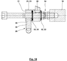
- the locking element 16 is supported via a locking spring 22 on a support element 23. If the support element 23 in a locking position 41, in accordance with Fig. 1 the bearing pin 6 between the guide surface 14 of the attachment hook 3 and the locking element 16 is braced (in Fig. 4 not shown), moved in the direction of the locking force 17 and in a locking direction 24, this leads to a change in the bias of the locking spring 22 and thus a change in the locking force 17th
- the support member 23 is formed as closed in the direction of the locking element 16 sleeve 25 having a substantially U-shaped longitudinal section.
- the sleeve 25 is pivotable about a longitudinal axis 38 thereof, which is oriented coaxially to the locking direction 24.
- a forced coupling of a pivoting movement of the sleeve 25 about its longitudinal axis 38 with a movement in the locking direction 24 or along the longitudinal axis 38, at least over a partial pivot angle, takes place in that a radial guide projection 26 of the support element 23, which in Fig. 4 shown dashed, engages in the backdrop 10th
- the guide projection 26 For an operating position for which the locking force 17 of the locking spring 22 is minimal, the guide projection 26 abuts against a contact point 27 of the link 10.
- the support element 23 in a drive direction 40 here a pivoting about the longitudinal axis 38
- locking position 41 pivots, slides the guide projection 26 along the locking element 16 facing away from the guide surface 28 of the gate 10 to a center here contact point 39.
- the guide surface 28 is, as in Fig.
- the support element 23 is pivoted via the actuating lever 30, which in this case is fastened directly thereto.
- the scenery 10 is different from the embodiment according to Fig. 4 formed: In the locking position 41 in the region of the contact point 39 has a Rastiervertiefung, so that upon reaching the pivot angle which corresponds to the locking position 41, the guide projection 26 due to the locking force 17 in the locking spring 22 in the Rastiervertiefung is pressed, whereby an unintentional pivoting back of the operating lever is prevented.
- the gate 10 for the inventive embodiment according to Fig. 4 not formed with such a Rastierverianaung in the region of the contact point 39. Rather, the guide surface 28 is monotonically or continuously inclined between the contact point 27 and the contact point in the locking position, wherein the contact point 39 of the guide surface 28 in the locking position 41 has the smallest distance from the locking element 16. However, it is also possible that in the region of the contact point 39, the guide surface is oriented transversely to the longitudinal axis 38 (in any case, without a Rastiervertiefung in the region of the contact point 39).
- the actuator 29 is partially decoupled from the support member 16 as follows for the inventive design:
- the bearing pins 6, 7 are inserted into the receptacles 12, 21 of the attachment hook 3, as explained for example in the above-mentioned product brochures of the applicant.
- the fastening device 1 is initially in a release position 35, as this particular in Fig. 6 is shown.
- the guide projection 26 is pivoted out of the slot 10 and displaced away in the direction of the longitudinal axis 38 relative to the slide 10 of the receptacle 12 (s. Fig. 6 and Fig. 7 ).
- the locking element 16 is in the release position 35, the receptacle 12 free, so that the associated bearing pin 6 can be inserted into the receptacle 12.
- the gate 9 has a section 42, which is rectilinear and parallel to the longitudinal axis 38. If the actuator 29 is moved with the coupling portion 31 along the portion 42 of the initial position 37 in an intermediate position 43, takes the coupling portion 31 via the Rastierfeder 33, the support member 23 in the direction of the receptacle 12 with. In this case, the guide projection 26 of the support member 23 moves in the direction of the receptacle 12 and thus in the axial region in which the link 10 is arranged. However, the guide projection 26 is still swung out of the gate 10 continues.
- a further movement of the actuating member 29 takes place starting from the intermediate position 43 via a section 44 of the link 9, which is inclined relative to the circumferential direction about the longitudinal axis 38 at an acute angle.
- This has the consequence that for the movement of the actuator 29 via the portion 44 of the coupling portion 31 performs a slight movement in the locking direction 24 and a superimposed movement in the drive direction 40, wherein the ratio of movement in the locking direction 24 and in the drive direction 40 by the inclination of Setting 9 is specified in section 44.
- the scenes 9 and 10 are located on different sides of the longitudinal axis 38, so that the movement of the formed by the operating lever 30 guide projection 36 in Fig. 4 from top to bottom in the direction of the longitudinal axis 38 is connected to the movement of the projection 26 from bottom to top in the direction of the longitudinal axis. Since in the region of the portion 44, the locking member 16 has already made contact with the bearing pin 6, increases with the movement of the actuator 29 along the portion 44 already the locking force 17 in the locking spring 22, wherein the extent of change of the locking force 17 in dependence the pivoting in the drive direction 40 depends on the inclination of the guide surface 28.
- the extent of change in the biasing force of the Rastierfeder 33 with a pivoting in the drive direction 40 depends on both the inclination of the link 9 in the section 44 and the inclination of the guide surface 28.
- the actuator 29 and its guide projection 36 has reached an intermediate position 45, in which the link 9 a Rasti protrusion 46 has, which limits a Rastierverianaung 47 in the backdrop 9.
- the region of the Rastiervorsprungs 46 of the guide projection 36 is displaced in the link 9 furthest in the locking direction 24 in the direction of the receptacle 12.
- the actuating member 29 is moved over the last section 48 until the guide projection 36 has reached a locking position 49 in the slot 9, in which the guide projection 36 is arranged in the Rastierverianaung 47.
- the locking force 17 in the locking spring 22 depends on the movement in the drive direction 40 and the sliding of the guide projection 26 along the guide surface 28, while the locking force 17 is not affected by the Preload force of the Rastierfeder 33 and the contour of the gate 9 in the sections 44, 47 with the Rastiervorsprung 46 and the Rastierverianaung 47.
- the locking position 49 on the one hand, the maximum locking force 17 is reached.
- the guide projection 36 is in the Rastierverianaung 47, whereby the actuator 29 is secured against unintentional movement away from the locking position 49.
- the securing force against movement be predefined by the rigidity of the Rastierfeder 33 and the contour of the gate 9 in the region of the sections 44, 48 and in particular the axial offset between the Rastiervorsprung 46 relative to the Rastierverianaung 47.
- a lock can be such that the mere application of forces on the actuator 29 in the drive direction 40 does not lead to release the detent, but manual actuation forces must be applied to the actuator 29 in the direction of the longitudinal axis 38 to release the lock.
- the spring stiffness can be adjusted individually depending on the needs on the one hand for the locking of the locking element 16 and on the other hand for bringing the detent.
- the locking spring 22 has a greater rigidity than the Rastierfeder 33.
- the locking spring 22 and the Rastierfeder 33 are each formed as a spiral springs 50, 51.
- each a package of disc springs 52, 53 use.
- an adjusting device 54 is present, via which a fine adjustment of the fastening device 1 is possible, in particular for adaptation to different manufacturing tolerances and different component variants.
- the axial Abstützort of the locking element 16 spring base of the locking spring 22 can be adjusted.
- the locking element 16 can already come to rest in the section 42 for abutment with the bearing journal 6 arranged in the receptacle 12. However, this preferably takes place only in the region of the subsection 44.
- the guide projection 36 forms a detent element 56 which interacts with the detent recess 47.
- design criteria discussed above may be used individually without realizing the other design criteria or in any combination of multiple design criteria. Preferably, however, the stated design criteria are used cumulatively.
Landscapes
- Engineering & Computer Science (AREA)
- Mechanical Engineering (AREA)
- Mining & Mineral Resources (AREA)
- Civil Engineering (AREA)
- General Engineering & Computer Science (AREA)
- Structural Engineering (AREA)
- Life Sciences & Earth Sciences (AREA)
- Environmental Sciences (AREA)
- Zoology (AREA)
- Soil Sciences (AREA)
- Lock And Its Accessories (AREA)
- Soil Working Implements (AREA)
- Agricultural Machines (AREA)
Claims (12)
- Dispositif de fixation (1) pour une fixation d'un équipement (2) sur un véhicule de travail (3), aveca) un élément de verrouillage (16) pour un logement (12) disposé sur le véhicule de travail, l'élément de verrouillage (16) étant, dans une position de verrouillage (41), manoeuvré dans une direction de verrouillage (24) par le biais d'un ressort de verrouillage (22), et étant appuyé sur un
élément d'appui (23) par le biais du ressort de verrouillage (22), un tourillon de l'équipement pouvant, avec une force de verrouillage, être serré et fixé entre le logement et l'élément de verrouillage, etb) un organe d'actionnement (29) mobile manuellement,ba) qui, dans une direction d'entraînement (40), est couplé à l'élément d'appui (23) pour un point de pied de ressort du ressort de verrouillage (22) de telle sorte qu'un mouvement de l'organe d'actionnement (29) dans la direction d'entraînement (40) provoque un mouvement de l'élément d'appui (23) de telle sorte que la force de verrouillage (17) du ressort de verrouillage (22) dans la direction de verrouillage (24) varie,bb) qui est mobile vis-à-vis de l'élément d'appui (23) dans une direction d'encliquetage (34) qui s'écarte de la direction d'entraînement (40), sans que la force de verrouillage (17) du ressort de verrouillage (22) dans la direction de verrouillage (24) varie, etc) un système d'encliquetage (55) par le biais duquel l'organe d'actionnement (29) est, dans la position de verrouillage (41), bloqué vis-à-vis d'un mouvement indésirable, un élément d'encliquetage (56) étant, dans le système d'encliquetage (55), manoeuvré par le biais d'un ressort d'encliquetage (33) dans la direction d'encliquetage (34) dans un creux d'encliquetage (47). - Dispositif de fixation (1) selon la revendication 1, caractérisé en ce que l'organe d'actionnement (29) est mobile dans la direction d'encliquetage (34) dans une zone extrême d'un mouvement dans la direction d'entraînement (40), ce qui fait que l'élément de verrouillage (16) libère le logement (12).
- Dispositif de fixation (1) selon l'une des revendications précédentes, caractérisé en ce que l'organe d'actionnement (29) et/ou l'élément d'appui (23) pour le point de pied de ressort du ressort de verrouillage (22) est/sont guidé(s) par le biais d'une coulisse (9 ; 10).
- Dispositif de fixation (1) selon la revendication 3, caractérisé en ce quea) l'organe d'actionnement (29) et/ou l'élément d'appui (23) pour le point de pied de ressort du ressort de verrouillage (22) sont/est pivoté(s) autour de la direction de verrouillage (24), etb) la coulisse (9) pour l'organe d'actionnement (2) et/ou la coulisse (10) pour l'élément d'appui (23) sont/est formée(s) dans une platine (4, 5).
- Dispositif de fixation (1) selon la revendication 4, caractérisé en ce que la coulisse (9) pour l'organe d'actionnement (29) et la coulisse (1) pour l'élément d'appui (23) sont formées dans une platine (4, 5), les deux platines (4, 5) étant disposées sur différents côtés de l'élément d'appui (23).
- Dispositif de fixation (1) selon l'une des revendications précédentes, caractérisé en ce que l'organe d'actionnement (2) pénètre dans la coulisse (9) affectée sur toute la course d'actionnement de l'organe d'actionnement (29).
- Dispositif de fixation (1) selon l'une des revendications précédentes, caractérisé en ce qu'une saillie de guidage (26) de l'élément d'appui (23)a) est disposée dans la coulisse (10) affectée pour une plage angulaire de pivotement dans laquelle une variation de la force de verrouillage (17) du ressort de verrouillage (22) s'effectue dans la direction de verrouillage (24), etb) est disposée à l'extérieur de la coulisse (10) pour une autre plage angulaire de pivotement dans laquelle l'élément de verrouillage (16) est extrait du logement (12) ou est introduit dans celui-ci.
- Dispositif de fixation (1) selon l'une des revendications précédentes, caractérisé en ce que le ressort de verrouillage (22) et/ou le ressort d'encliquetage (33) sont/est constitué(s) d'au moins une rondelle Belleville (52 ; 53).
- Dispositif de fixation (1) selon l'une des revendications précédentes, caractérisé en ce que l'élément d'appui (23) est constitué en tant que manchon (25), et l'organe d'actionnement (29) possède un tronçon de couplage (31) qui est guidé dans un creux du manchon (25) de façon coulissante axialement dans la direction d'encliquetage (34) mais bloqué en rotation dans la direction d'entraînement (40).
- Dispositif de fixation (1) selon la revendication 9, caractérisé en ce que le ressort d'encliquetage (33) est disposé dans l'intérieur du manchon (25),a) un point de pied de ressort du ressort d'encliquetage (33) étant appuyé sur le manchon (25), etb) l'autre point de pied de ressort du ressort d'encliquetage (33) étant appuyé sur le tronçon de couplage (31).
- Dispositif de fixation (1) selon l'une des revendications précédentes, caractérisé en ce que, entre l'organe d' actionnement (29) et l'élément d' appui (23), u n convertisseur (57) agit, qui convertit une force d'actionnement manuelle agissant sur l'organe d'actionnement (29) en une force plus importante qui fait varier la force de verrouillage (17) du ressort de verrouillage (22).
- Groupe d'éléments de construction de véhicule de travail, avec un véhicule de travail et au moins un équipement qui est fixé sur le véhicule de travail de façon détachable par le bais d'un dispositif de fixation (1) selon l' une des revendications précédentes.
Applications Claiming Priority (1)
| Application Number | Priority Date | Filing Date | Title |
|---|---|---|---|
| DE102013108171.1A DE102013108171B4 (de) | 2013-07-30 | 2013-07-30 | Befestigungsvorrichtung für eine Befestigung eines Arbeitsgeräts an einem Arbeitsfahrzeug |
Publications (3)
| Publication Number | Publication Date |
|---|---|
| EP2840186A2 EP2840186A2 (fr) | 2015-02-25 |
| EP2840186A3 EP2840186A3 (fr) | 2015-05-06 |
| EP2840186B1 true EP2840186B1 (fr) | 2017-05-10 |
Family
ID=51224831
Family Applications (1)
| Application Number | Title | Priority Date | Filing Date |
|---|---|---|---|
| EP14178643.4A Active EP2840186B1 (fr) | 2013-07-30 | 2014-07-25 | Dispositif de fixation d'un chargeur frontal sur un véhicule de travail |
Country Status (2)
| Country | Link |
|---|---|
| EP (1) | EP2840186B1 (fr) |
| DE (1) | DE102013108171B4 (fr) |
Cited By (5)
| Publication number | Priority date | Publication date | Assignee | Title |
|---|---|---|---|---|
| DE202023002870U1 (de) | 2023-07-13 | 2024-11-28 | Wilhelm Stoll Maschinenfabrik Gmbh | Frontlader, Arbeitsfahrzeug und Arbeitsfahrzeugsystem |
| EP4491806A1 (fr) | 2023-07-13 | 2025-01-15 | Wilhelm Stoll Maschinenfabrik GmbH | Chargeur frontal, véhicule de travail et système de véhicule de travail |
| EP4491807A1 (fr) | 2023-07-13 | 2025-01-15 | Wilhelm Stoll Maschinenfabrik GmbH | Procédé de couplage automatique d'un chargeur frontal avec un véhicule de travail, dispositif de couplage de chargeur frontal automatique, véhicule de travail et système de véhicule de travail |
| EP4553233A1 (fr) | 2023-11-10 | 2025-05-14 | Wilhelm Stoll Maschinenfabrik GmbH | Accessoire, combinaison de véhicules et produit programme informatique |
| DE202023003153U1 (de) | 2023-11-10 | 2026-05-07 | Bucher Hydraulics Gmbh | Anbaugerät, Fahrzeugkombination, Computerprogrammprodukt und Verwendung einer Steuereinheit |
Families Citing this family (1)
| Publication number | Priority date | Publication date | Assignee | Title |
|---|---|---|---|---|
| US10208451B2 (en) * | 2015-10-26 | 2019-02-19 | Kubota Corporation | Work vehicle and front loader |
Family Cites Families (2)
| Publication number | Priority date | Publication date | Assignee | Title |
|---|---|---|---|---|
| DE3229947C2 (de) | 1982-08-12 | 1994-05-26 | Stoll Maschf Gmbh Wilhelm | An einen Schlepper lösbar anschließbarer Abstellfrontlader |
| FI100845B (fi) * | 1995-12-20 | 1998-03-13 | Paavo Antero Viikki | Työntövarren kytkinkoura |
-
2013
- 2013-07-30 DE DE102013108171.1A patent/DE102013108171B4/de not_active Expired - Fee Related
-
2014
- 2014-07-25 EP EP14178643.4A patent/EP2840186B1/fr active Active
Non-Patent Citations (1)
| Title |
|---|
| None * |
Cited By (6)
| Publication number | Priority date | Publication date | Assignee | Title |
|---|---|---|---|---|
| DE202023002870U1 (de) | 2023-07-13 | 2024-11-28 | Wilhelm Stoll Maschinenfabrik Gmbh | Frontlader, Arbeitsfahrzeug und Arbeitsfahrzeugsystem |
| EP4491806A1 (fr) | 2023-07-13 | 2025-01-15 | Wilhelm Stoll Maschinenfabrik GmbH | Chargeur frontal, véhicule de travail et système de véhicule de travail |
| EP4491807A1 (fr) | 2023-07-13 | 2025-01-15 | Wilhelm Stoll Maschinenfabrik GmbH | Procédé de couplage automatique d'un chargeur frontal avec un véhicule de travail, dispositif de couplage de chargeur frontal automatique, véhicule de travail et système de véhicule de travail |
| EP4553233A1 (fr) | 2023-11-10 | 2025-05-14 | Wilhelm Stoll Maschinenfabrik GmbH | Accessoire, combinaison de véhicules et produit programme informatique |
| EP4729702A2 (fr) | 2023-11-10 | 2026-04-22 | Wilhelm Stoll Maschinenfabrik GmbH | Accessoire, combinaison de véhicules et produit programme informatique |
| DE202023003153U1 (de) | 2023-11-10 | 2026-05-07 | Bucher Hydraulics Gmbh | Anbaugerät, Fahrzeugkombination, Computerprogrammprodukt und Verwendung einer Steuereinheit |
Also Published As
| Publication number | Publication date |
|---|---|
| EP2840186A2 (fr) | 2015-02-25 |
| DE102013108171A1 (de) | 2015-02-05 |
| DE102013108171B4 (de) | 2015-10-01 |
| EP2840186A3 (fr) | 2015-05-06 |
Similar Documents
| Publication | Publication Date | Title |
|---|---|---|
| EP2840186B1 (fr) | Dispositif de fixation d'un chargeur frontal sur un véhicule de travail | |
| EP2705205B1 (fr) | Charnière | |
| EP3683389A1 (fr) | Mécanisme de réglage pour parties de meuble | |
| EP3423313A1 (fr) | Charnière d'ouvrant pour capot avant d'un véhicule, comportant un appui déplaçable pour un déclencheur de levage | |
| WO2006108603A2 (fr) | Mecanisme de classeur a anneaux | |
| DE202008005083U1 (de) | Presszange | |
| EP3341545B1 (fr) | Dispositif de positionnement de deux portes coulissantes et meuble | |
| EP4077852B1 (fr) | Dispositif de verrouillage amovible de deux éléments de meuble | |
| EP4077844B1 (fr) | Dispositif pour guider une porte coulissante ou une porte accordéon | |
| EP3812053A1 (fr) | Appareil de nettoyage haute pression et procédé de montage d'un appareil de nettoyage haute pression | |
| DE102012012134A1 (de) | Sicherheitssitzvorrichtung | |
| WO2016155934A1 (fr) | Système de poignée de porte d'un véhicule automobile | |
| EP2630320B1 (fr) | Armature de tiroir pour relier un tiroir à une serrure centrale | |
| DE102009050875A1 (de) | Vorrichtung zum Öffnen und Schließen von Fenstern an Wohnwagen, Wohnmobilen und dergleichen | |
| DE202008016705U1 (de) | Kraftfahrzeugschloss | |
| DE102016118139A1 (de) | Trennscheibe für Paniknuss | |
| EP2025853A2 (fr) | Dispositif d'entraîneur pour un dispositif d'entraînement de porte, un tel dispositif d'entraînement de porte et une porte | |
| DE102004010136B3 (de) | Vorrichtung zur Betätigung eines kombinierten Heck- und Verdeckdeckels für ein Cabriolet-Fahrzeug | |
| EP3117734B9 (fr) | Tendeur de sangle | |
| WO2011113740A1 (fr) | Charnière | |
| EP4453327B1 (fr) | Dispositif à changement rapide | |
| EP2770154B1 (fr) | Élément de regroupement pour le regroupement d'au moins deux cordons d'actionnement pour une installation d'ombrage | |
| EP3564468A1 (fr) | Ferrure antipanique pourvue d'une boîte de vitesses compacte pouvant être commutée à gauche et à droite | |
| EP3109382B1 (fr) | Serrure | |
| EP2865831B1 (fr) | Serrure |
Legal Events
| Date | Code | Title | Description |
|---|---|---|---|
| PUAI | Public reference made under article 153(3) epc to a published international application that has entered the european phase |
Free format text: ORIGINAL CODE: 0009012 |
|
| 17P | Request for examination filed |
Effective date: 20140725 |
|
| AK | Designated contracting states |
Kind code of ref document: A2 Designated state(s): AL AT BE BG CH CY CZ DE DK EE ES FI FR GB GR HR HU IE IS IT LI LT LU LV MC MK MT NL NO PL PT RO RS SE SI SK SM TR |
|
| AX | Request for extension of the european patent |
Extension state: BA ME |
|
| PUAL | Search report despatched |
Free format text: ORIGINAL CODE: 0009013 |
|
| AK | Designated contracting states |
Kind code of ref document: A3 Designated state(s): AL AT BE BG CH CY CZ DE DK EE ES FI FR GB GR HR HU IE IS IT LI LT LU LV MC MK MT NL NO PL PT RO RS SE SI SK SM TR |
|
| AX | Request for extension of the european patent |
Extension state: BA ME |
|
| RIC1 | Information provided on ipc code assigned before grant |
Ipc: A01D 87/00 20060101ALI20150330BHEP Ipc: A01B 59/06 20060101ALI20150330BHEP Ipc: E02F 3/627 20060101ALI20150330BHEP Ipc: E02F 3/36 20060101AFI20150330BHEP |
|
| R17P | Request for examination filed (corrected) |
Effective date: 20150528 |
|
| RBV | Designated contracting states (corrected) |
Designated state(s): AL AT BE BG CH CY CZ DE DK EE ES FI FR GB GR HR HU IE IS IT LI LT LU LV MC MK MT NL NO PL PT RO RS SE SI SK SM TR |
|
| 17Q | First examination report despatched |
Effective date: 20160712 |
|
| GRAP | Despatch of communication of intention to grant a patent |
Free format text: ORIGINAL CODE: EPIDOSNIGR1 |
|
| INTG | Intention to grant announced |
Effective date: 20161201 |
|
| GRAS | Grant fee paid |
Free format text: ORIGINAL CODE: EPIDOSNIGR3 |
|
| GRAJ | Information related to disapproval of communication of intention to grant by the applicant or resumption of examination proceedings by the epo deleted |
Free format text: ORIGINAL CODE: EPIDOSDIGR1 |
|
| GRAL | Information related to payment of fee for publishing/printing deleted |
Free format text: ORIGINAL CODE: EPIDOSDIGR3 |
|
| GRAR | Information related to intention to grant a patent recorded |
Free format text: ORIGINAL CODE: EPIDOSNIGR71 |
|
| GRAA | (expected) grant |
Free format text: ORIGINAL CODE: 0009210 |
|
| INTC | Intention to grant announced (deleted) | ||
| AK | Designated contracting states |
Kind code of ref document: B1 Designated state(s): AL AT BE BG CH CY CZ DE DK EE ES FI FR GB GR HR HU IE IS IT LI LT LU LV MC MK MT NL NO PL PT RO RS SE SI SK SM TR |
|
| INTG | Intention to grant announced |
Effective date: 20170404 |
|
| REG | Reference to a national code |
Ref country code: GB Ref legal event code: FG4D Free format text: NOT ENGLISH |
|
| REG | Reference to a national code |
Ref country code: AT Ref legal event code: REF Ref document number: 892460 Country of ref document: AT Kind code of ref document: T Effective date: 20170515 Ref country code: CH Ref legal event code: EP |
|
| REG | Reference to a national code |
Ref country code: IE Ref legal event code: FG4D Free format text: LANGUAGE OF EP DOCUMENT: GERMAN |
|
| REG | Reference to a national code |
Ref country code: DE Ref legal event code: R096 Ref document number: 502014003730 Country of ref document: DE |
|
| REG | Reference to a national code |
Ref country code: FR Ref legal event code: PLFP Year of fee payment: 4 |
|
| REG | Reference to a national code |
Ref country code: SE Ref legal event code: TRGR |
|
| REG | Reference to a national code |
Ref country code: NL Ref legal event code: MP Effective date: 20170510 |
|
| REG | Reference to a national code |
Ref country code: LT Ref legal event code: MG4D |
|
| PG25 | Lapsed in a contracting state [announced via postgrant information from national office to epo] |
Ref country code: ES Free format text: LAPSE BECAUSE OF FAILURE TO SUBMIT A TRANSLATION OF THE DESCRIPTION OR TO PAY THE FEE WITHIN THE PRESCRIBED TIME-LIMIT Effective date: 20170510 Ref country code: NO Free format text: LAPSE BECAUSE OF FAILURE TO SUBMIT A TRANSLATION OF THE DESCRIPTION OR TO PAY THE FEE WITHIN THE PRESCRIBED TIME-LIMIT Effective date: 20170810 Ref country code: FI Free format text: LAPSE BECAUSE OF FAILURE TO SUBMIT A TRANSLATION OF THE DESCRIPTION OR TO PAY THE FEE WITHIN THE PRESCRIBED TIME-LIMIT Effective date: 20170510 Ref country code: LT Free format text: LAPSE BECAUSE OF FAILURE TO SUBMIT A TRANSLATION OF THE DESCRIPTION OR TO PAY THE FEE WITHIN THE PRESCRIBED TIME-LIMIT Effective date: 20170510 Ref country code: GR Free format text: LAPSE BECAUSE OF FAILURE TO SUBMIT A TRANSLATION OF THE DESCRIPTION OR TO PAY THE FEE WITHIN THE PRESCRIBED TIME-LIMIT Effective date: 20170811 Ref country code: HR Free format text: LAPSE BECAUSE OF FAILURE TO SUBMIT A TRANSLATION OF THE DESCRIPTION OR TO PAY THE FEE WITHIN THE PRESCRIBED TIME-LIMIT Effective date: 20170510 |
|
| PG25 | Lapsed in a contracting state [announced via postgrant information from national office to epo] |
Ref country code: NL Free format text: LAPSE BECAUSE OF FAILURE TO SUBMIT A TRANSLATION OF THE DESCRIPTION OR TO PAY THE FEE WITHIN THE PRESCRIBED TIME-LIMIT Effective date: 20170510 Ref country code: IS Free format text: LAPSE BECAUSE OF FAILURE TO SUBMIT A TRANSLATION OF THE DESCRIPTION OR TO PAY THE FEE WITHIN THE PRESCRIBED TIME-LIMIT Effective date: 20170910 Ref country code: BG Free format text: LAPSE BECAUSE OF FAILURE TO SUBMIT A TRANSLATION OF THE DESCRIPTION OR TO PAY THE FEE WITHIN THE PRESCRIBED TIME-LIMIT Effective date: 20170810 Ref country code: LV Free format text: LAPSE BECAUSE OF FAILURE TO SUBMIT A TRANSLATION OF THE DESCRIPTION OR TO PAY THE FEE WITHIN THE PRESCRIBED TIME-LIMIT Effective date: 20170510 Ref country code: RS Free format text: LAPSE BECAUSE OF FAILURE TO SUBMIT A TRANSLATION OF THE DESCRIPTION OR TO PAY THE FEE WITHIN THE PRESCRIBED TIME-LIMIT Effective date: 20170510 Ref country code: PL Free format text: LAPSE BECAUSE OF FAILURE TO SUBMIT A TRANSLATION OF THE DESCRIPTION OR TO PAY THE FEE WITHIN THE PRESCRIBED TIME-LIMIT Effective date: 20170510 |
|
| PG25 | Lapsed in a contracting state [announced via postgrant information from national office to epo] |
Ref country code: DK Free format text: LAPSE BECAUSE OF FAILURE TO SUBMIT A TRANSLATION OF THE DESCRIPTION OR TO PAY THE FEE WITHIN THE PRESCRIBED TIME-LIMIT Effective date: 20170510 Ref country code: SK Free format text: LAPSE BECAUSE OF FAILURE TO SUBMIT A TRANSLATION OF THE DESCRIPTION OR TO PAY THE FEE WITHIN THE PRESCRIBED TIME-LIMIT Effective date: 20170510 Ref country code: EE Free format text: LAPSE BECAUSE OF FAILURE TO SUBMIT A TRANSLATION OF THE DESCRIPTION OR TO PAY THE FEE WITHIN THE PRESCRIBED TIME-LIMIT Effective date: 20170510 Ref country code: CZ Free format text: LAPSE BECAUSE OF FAILURE TO SUBMIT A TRANSLATION OF THE DESCRIPTION OR TO PAY THE FEE WITHIN THE PRESCRIBED TIME-LIMIT Effective date: 20170510 Ref country code: RO Free format text: LAPSE BECAUSE OF FAILURE TO SUBMIT A TRANSLATION OF THE DESCRIPTION OR TO PAY THE FEE WITHIN THE PRESCRIBED TIME-LIMIT Effective date: 20170510 |
|
| REG | Reference to a national code |
Ref country code: DE Ref legal event code: R097 Ref document number: 502014003730 Country of ref document: DE |
|
| PG25 | Lapsed in a contracting state [announced via postgrant information from national office to epo] |
Ref country code: SM Free format text: LAPSE BECAUSE OF FAILURE TO SUBMIT A TRANSLATION OF THE DESCRIPTION OR TO PAY THE FEE WITHIN THE PRESCRIBED TIME-LIMIT Effective date: 20170510 Ref country code: IT Free format text: LAPSE BECAUSE OF FAILURE TO SUBMIT A TRANSLATION OF THE DESCRIPTION OR TO PAY THE FEE WITHIN THE PRESCRIBED TIME-LIMIT Effective date: 20170510 |
|
| REG | Reference to a national code |
Ref country code: CH Ref legal event code: PL |
|
| PLBE | No opposition filed within time limit |
Free format text: ORIGINAL CODE: 0009261 |
|
| STAA | Information on the status of an ep patent application or granted ep patent |
Free format text: STATUS: NO OPPOSITION FILED WITHIN TIME LIMIT |
|
| 26N | No opposition filed |
Effective date: 20180213 |
|
| REG | Reference to a national code |
Ref country code: IE Ref legal event code: MM4A |
|
| PG25 | Lapsed in a contracting state [announced via postgrant information from national office to epo] |
Ref country code: IE Free format text: LAPSE BECAUSE OF NON-PAYMENT OF DUE FEES Effective date: 20170725 Ref country code: LI Free format text: LAPSE BECAUSE OF NON-PAYMENT OF DUE FEES Effective date: 20170731 Ref country code: CH Free format text: LAPSE BECAUSE OF NON-PAYMENT OF DUE FEES Effective date: 20170731 |
|
| PG25 | Lapsed in a contracting state [announced via postgrant information from national office to epo] |
Ref country code: SI Free format text: LAPSE BECAUSE OF FAILURE TO SUBMIT A TRANSLATION OF THE DESCRIPTION OR TO PAY THE FEE WITHIN THE PRESCRIBED TIME-LIMIT Effective date: 20170510 |
|
| REG | Reference to a national code |
Ref country code: BE Ref legal event code: MM Effective date: 20170731 |
|
| PG25 | Lapsed in a contracting state [announced via postgrant information from national office to epo] |
Ref country code: LU Free format text: LAPSE BECAUSE OF NON-PAYMENT OF DUE FEES Effective date: 20170725 |
|
| REG | Reference to a national code |
Ref country code: FR Ref legal event code: PLFP Year of fee payment: 5 |
|
| PG25 | Lapsed in a contracting state [announced via postgrant information from national office to epo] |
Ref country code: BE Free format text: LAPSE BECAUSE OF NON-PAYMENT OF DUE FEES Effective date: 20170731 |
|
| PG25 | Lapsed in a contracting state [announced via postgrant information from national office to epo] |
Ref country code: MT Free format text: LAPSE BECAUSE OF FAILURE TO SUBMIT A TRANSLATION OF THE DESCRIPTION OR TO PAY THE FEE WITHIN THE PRESCRIBED TIME-LIMIT Effective date: 20170510 |
|
| GBPC | Gb: european patent ceased through non-payment of renewal fee |
Effective date: 20180725 |
|
| PG25 | Lapsed in a contracting state [announced via postgrant information from national office to epo] |
Ref country code: GB Free format text: LAPSE BECAUSE OF NON-PAYMENT OF DUE FEES Effective date: 20180725 |
|
| PG25 | Lapsed in a contracting state [announced via postgrant information from national office to epo] |
Ref country code: MC Free format text: LAPSE BECAUSE OF FAILURE TO SUBMIT A TRANSLATION OF THE DESCRIPTION OR TO PAY THE FEE WITHIN THE PRESCRIBED TIME-LIMIT Effective date: 20170510 Ref country code: HU Free format text: LAPSE BECAUSE OF FAILURE TO SUBMIT A TRANSLATION OF THE DESCRIPTION OR TO PAY THE FEE WITHIN THE PRESCRIBED TIME-LIMIT; INVALID AB INITIO Effective date: 20140725 |
|
| PG25 | Lapsed in a contracting state [announced via postgrant information from national office to epo] |
Ref country code: CY Free format text: LAPSE BECAUSE OF FAILURE TO SUBMIT A TRANSLATION OF THE DESCRIPTION OR TO PAY THE FEE WITHIN THE PRESCRIBED TIME-LIMIT Effective date: 20170510 |
|
| PG25 | Lapsed in a contracting state [announced via postgrant information from national office to epo] |
Ref country code: MK Free format text: LAPSE BECAUSE OF FAILURE TO SUBMIT A TRANSLATION OF THE DESCRIPTION OR TO PAY THE FEE WITHIN THE PRESCRIBED TIME-LIMIT Effective date: 20170510 |
|
| PG25 | Lapsed in a contracting state [announced via postgrant information from national office to epo] |
Ref country code: TR Free format text: LAPSE BECAUSE OF FAILURE TO SUBMIT A TRANSLATION OF THE DESCRIPTION OR TO PAY THE FEE WITHIN THE PRESCRIBED TIME-LIMIT Effective date: 20170510 |
|
| PG25 | Lapsed in a contracting state [announced via postgrant information from national office to epo] |
Ref country code: PT Free format text: LAPSE BECAUSE OF FAILURE TO SUBMIT A TRANSLATION OF THE DESCRIPTION OR TO PAY THE FEE WITHIN THE PRESCRIBED TIME-LIMIT Effective date: 20170510 |
|
| PG25 | Lapsed in a contracting state [announced via postgrant information from national office to epo] |
Ref country code: AL Free format text: LAPSE BECAUSE OF FAILURE TO SUBMIT A TRANSLATION OF THE DESCRIPTION OR TO PAY THE FEE WITHIN THE PRESCRIBED TIME-LIMIT Effective date: 20170510 |
|
| PGFP | Annual fee paid to national office [announced via postgrant information from national office to epo] |
Ref country code: DE Payment date: 20250710 Year of fee payment: 12 |
|
| PGFP | Annual fee paid to national office [announced via postgrant information from national office to epo] |
Ref country code: FR Payment date: 20250723 Year of fee payment: 12 Ref country code: AT Payment date: 20250721 Year of fee payment: 12 |
|
| PGFP | Annual fee paid to national office [announced via postgrant information from national office to epo] |
Ref country code: SE Payment date: 20250723 Year of fee payment: 12 |