EP2840233A2 - Dampfturbine - Google Patents
Dampfturbine Download PDFInfo
- Publication number
- EP2840233A2 EP2840233A2 EP14174843.4A EP14174843A EP2840233A2 EP 2840233 A2 EP2840233 A2 EP 2840233A2 EP 14174843 A EP14174843 A EP 14174843A EP 2840233 A2 EP2840233 A2 EP 2840233A2
- Authority
- EP
- European Patent Office
- Prior art keywords
- outer ring
- steam turbine
- annular slit
- diaphragm outer
- turbine
- Prior art date
- Legal status (The legal status is an assumption and is not a legal conclusion. Google has not performed a legal analysis and makes no representation as to the accuracy of the status listed.)
- Granted
Links
Images


Classifications
-
- F—MECHANICAL ENGINEERING; LIGHTING; HEATING; WEAPONS; BLASTING
- F01—MACHINES OR ENGINES IN GENERAL; ENGINE PLANTS IN GENERAL; STEAM ENGINES
- F01D—NON-POSITIVE DISPLACEMENT MACHINES OR ENGINES, e.g. STEAM TURBINES
- F01D25/00—Component parts, details, or accessories, not provided for in, or of interest apart from, other groups
- F01D25/32—Collecting of condensation water; Drainage ; Removing solid particles
-
- F—MECHANICAL ENGINEERING; LIGHTING; HEATING; WEAPONS; BLASTING
- F01—MACHINES OR ENGINES IN GENERAL; ENGINE PLANTS IN GENERAL; STEAM ENGINES
- F01D—NON-POSITIVE DISPLACEMENT MACHINES OR ENGINES, e.g. STEAM TURBINES
- F01D9/00—Stators
- F01D9/02—Nozzles; Nozzle boxes; Stator blades; Guide conduits, e.g. individual nozzles
- F01D9/04—Nozzles; Nozzle boxes; Stator blades; Guide conduits, e.g. individual nozzles forming ring or sector
- F01D9/041—Nozzles; Nozzle boxes; Stator blades; Guide conduits, e.g. individual nozzles forming ring or sector using blades
-
- F—MECHANICAL ENGINEERING; LIGHTING; HEATING; WEAPONS; BLASTING
- F01—MACHINES OR ENGINES IN GENERAL; ENGINE PLANTS IN GENERAL; STEAM ENGINES
- F01D—NON-POSITIVE DISPLACEMENT MACHINES OR ENGINES, e.g. STEAM TURBINES
- F01D1/00—Non-positive-displacement machines or engines, e.g. steam turbines
-
- F—MECHANICAL ENGINEERING; LIGHTING; HEATING; WEAPONS; BLASTING
- F01—MACHINES OR ENGINES IN GENERAL; ENGINE PLANTS IN GENERAL; STEAM ENGINES
- F01D—NON-POSITIVE DISPLACEMENT MACHINES OR ENGINES, e.g. STEAM TURBINES
- F01D9/00—Stators
- F01D9/02—Nozzles; Nozzle boxes; Stator blades; Guide conduits, e.g. individual nozzles
- F01D9/04—Nozzles; Nozzle boxes; Stator blades; Guide conduits, e.g. individual nozzles forming ring or sector
- F01D9/047—Nozzle boxes
-
- F—MECHANICAL ENGINEERING; LIGHTING; HEATING; WEAPONS; BLASTING
- F05—INDEXING SCHEMES RELATING TO ENGINES OR PUMPS IN VARIOUS SUBCLASSES OF CLASSES F01-F04
- F05D—INDEXING SCHEME FOR ASPECTS RELATING TO NON-POSITIVE-DISPLACEMENT MACHINES OR ENGINES, GAS-TURBINES OR JET-PROPULSION PLANTS
- F05D2220/00—Application
- F05D2220/30—Application in turbines
- F05D2220/31—Application in turbines in steam turbines
-
- F—MECHANICAL ENGINEERING; LIGHTING; HEATING; WEAPONS; BLASTING
- F05—INDEXING SCHEMES RELATING TO ENGINES OR PUMPS IN VARIOUS SUBCLASSES OF CLASSES F01-F04
- F05D—INDEXING SCHEME FOR ASPECTS RELATING TO NON-POSITIVE-DISPLACEMENT MACHINES OR ENGINES, GAS-TURBINES OR JET-PROPULSION PLANTS
- F05D2260/00—Function
- F05D2260/60—Fluid transfer
- F05D2260/602—Drainage
-
- F—MECHANICAL ENGINEERING; LIGHTING; HEATING; WEAPONS; BLASTING
- F05—INDEXING SCHEMES RELATING TO ENGINES OR PUMPS IN VARIOUS SUBCLASSES OF CLASSES F01-F04
- F05D—INDEXING SCHEME FOR ASPECTS RELATING TO NON-POSITIVE-DISPLACEMENT MACHINES OR ENGINES, GAS-TURBINES OR JET-PROPULSION PLANTS
- F05D2260/00—Function
- F05D2260/60—Fluid transfer
- F05D2260/608—Aeration, ventilation, dehumidification or moisture removal of closed spaces
Definitions
- Embodiments described herein relate generally to a steam turbine.
- a temperature and a pressure of steam being a working fluid are low. Accordingly, a part of the steam is condensed during expansion work to be water droplets to adhere to an inner wall of a steam passage, a stationary blade, and a rotor blade.
- the water droplets generated at the steam passage grow into the water droplets whose particle diameters are large.
- the water droplets whose particle diameters are large collide with a leading edge and so on of the rotor blade, and thereby, the rotor blade is eroded and a collision resistance relative to a rotation of the rotor blade is generated to lower turbine efficiency.
- FIG. 12 is a view illustrating a meridian cross section in a vicinity of a final turbine stage in a conventional low-pressure turbine. Note that in FIG. 12 , a dotted line represents a streamline of the steam, and a solid line represents a trace of the generated water droplets.
- diaphragm outer rings 310a, 310b, diaphragm inner rings 311a, 311b are included at an inner side of a casing 300.
- plural stationary blades 312a, 312b are supported in a circumferential direction to make up a stationary blade cascade.
- a rotor blade cascade in which plural rotor blades 322a, 322b are implanted into rotor disks 320a, 320b of a turbine rotor in the circumferential direction is made up.
- a single stage turbine stage is made up by the stationary blade cascade and the rotor blade cascade positioning at the immediate downstream thereof.
- FIG. 12 a final turbine stage 330 and a turbine stage 331 at upstream side for one stage than the final turbine stage 330 are illustrated.
- a speed energy of the steam expanded at the stationary blades 312a, 312b is converted into a rotational energy to generate a motive power.
- the steam expands along the steam passage which increases in size as it goes downstream.
- the water droplets are generated at a part where the pressure and the temperature of the steam descend, for example, at the turbine stage 331 which is at upstream for one stage than the final turbine stage 330.
- a part of the generated water droplets flows toward the diaphragm outer ring 310a of the turbine stage 330 affected by the centrifugal force and the coriolis force. Accordingly, a lot of water droplets adhere to an inner surface of the diaphragm outer ring 310a of the turbine stage 330 to form a water film.
- remaining water droplets collide with and adhere to a surface of the stationary blade 312a to form the water film.
- a water film reaching a trailing edge of the stationary blade 312a is blown and torn off by a steam flow at the trailing edge to be the water droplets.
- the water droplets collide with the rotor blade 322a at the immediate downstream side to erode the rotor blade 322a, activate a force in a reverse direction with a rotational direction to lower turbine efficiency.
- FIG. 13 is a view illustrating a distribution of wetness of the steam in a blade height direction of the stationary blade at the final turbine stage of the conventional low-pressure turbine.
- a vertical axis represents a blade height ratio in which each blade height position is divided by a blade height. For example, when the blade height ratio is "1", it indicates a blade tip of the stationary blade, and when the blade height ratio is "0" (zero), it indicates a blade root of the stationary blade.
- the wetness becomes high at the tip side of the stationary blade, namely, at the diaphragm outer ring side. Accordingly, an adverse effect caused by the generated water droplets becomes remarkable at the diaphragm outer ring side.
- the through holes are formed at a limited area between the stationary blade and the rotor blade, and therefore, it is impossible to enough expand a bore diameter. Accordingly, it is necessary to form a lot of through holes in the circumferential direction to uniformly remove the water film and the water droplets in the circumferential direction. This incurs complication of a manufacturing process, and increase in manufacturing cost.
- a steam turbine where wet steam flows in a turbine stage in low-pressure.
- This steam turbine includes: rotor blades implanted in a circumferential direction to a turbine rotor provided to penetrate in a casing; stationary blades provided at an immediate upstream side of the rotor blades in the circumferential direction, and making up a turbine stage together with the rotor blades; diaphragm outer rings provided inside the casing, each including an annular extending part surrounding a periphery of the rotor blades, and supporting the stationary blades from outside in a radial direction; and diaphragm inner rings supporting the stationary blades from inside in the radial direction.
- the steam turbine further includes: an annular slit formed at an inner surface of the diaphragm outer ring between the stationary blades and the rotor blades along the circumferential direction; and communication holes provided in plural at an outer surface of the diaphragm outer ring along the circumferential direction, communicated to the annular slit from the outer surface side of the diaphragm outer ring, and communicated to a suction part sucking liquid via the annular slit.
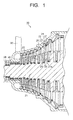
- FIG. 1 is a view illustrating a cross section in a vertical direction of a steam turbine 10 according to a first embodiment. Note that the steam turbine described hereinbelow is a low-pressure turbine.
- the steam turbine 10 includes a casing 20.
- a turbine rotor 21 is provided to penetrate in the casing 20.
- Rotor disks 21a are formed at the turbine rotor 21.
- Plural rotor blades 22 are implanted to the rotor disk 21a in a circumferential direction.
- Rotor blade cascades including the plural rotor blades 22 in the circumferential direction are made up in plural stages in an axial direction of the turbine rotor 21.
- the turbine rotor 21 is rotatably supported by a not-illustrated rotor bearing.
- Diaphragm outer rings 23 are provided at an inner side of the casing 20. Each diaphragm outer ring 23 extends annularly toward a downstream side, and includes an annular extending part 24 surrounding a periphery of the rotor blade 22. Diaphragm inner rings 25 are provided at an inner side of the diaphragm outer ring 23.
- plural stationary blades 26 are disposed in the circumferential direction between the diaphragm outer ring 23 and the diaphragm inner ring 25 to make up a stationary blade cascade.
- the diaphragm outer ring 23 supports the stationary blade 26 from outside in a radial direction.
- the diaphragm inner ring 25 supports the stationary blade 26 from inside in the radial direction.
- the stationary blade cascades are included in plural stages alternately with the rotor blade cascades in the axial direction of the turbine rotor 21. One turbine stage is made up by the stationary blade cascade and the rotor blade cascade positioning at an immediate downstream side.
- An annular steam passage 27 where main steam flows is formed between the diaphragm outer ring 23 and the diaphragm inner ring 25.
- a flow passage cross section of the steam passage 27 gradually expands as it goes, for example, downstream.
- a gland sealing part 28 is provided between the turbine rotor 21 and the casing 20 to prevent leakage of the steam toward outside.
- a sealing part 29 is provided between the turbine rotor 21 and the diaphragm inner ring 25 to prevent that the steam leaks therebetween toward downstream side.
- a steam inlet pipe (not-illustrated) to introduce the steam from a crossover pipe 30 into the steam turbine 10 is provided at the steam turbine 10.
- This steam inlet pipe is provided to penetrate the casing 20.
- An exhaust passage (not-illustrated) to exhaust the steam having performed expansion work at each turbine stage is provided at a downstream side of a final turbine stage. This exhaust passage is communicated to a condenser (not-illustrated).
- the final turbine stage is exemplified to be described as the turbine stage where the wet steam flows.
- the turbine stage where the wet steam flows is not limited to the final turbine stage. Accordingly, when the wet steam flows, the turbine stage includes the similar constitution as the following final turbine stage even if it is the turbine stage at upstream than the final turbine stage.
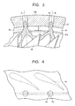
- FIG. 2 is a view illustrating a cross section in a vertical direction at an upper half side of the final turbine stage at the steam turbine 10 according to the first embodiment.
- FIG. 3 is a view illustrating an A-A cross section in FIG. 2 .
- FIG. 4 is a plan view when the diaphragm outer ring 23 of the steam turbine 10 according to the first embodiment is seen from outside in the radial direction. Note that in FIG. 2 and FIG. 3 , water films 80 adhered to the stationary blades 26, an annular slit 40, and a communication hole 50 are also illustrated.
- the annular extending part 24 of the diaphragm outer ring 23 surrounds the periphery of the rotor blade 22 with a minute gap.
- the annular slit 40 is formed between the stationary blade 26 at an inner surface of the diaphragm outer ring 23 and the rotor blade 22 along the circumferential direction. Namely, the annular slit 40 is made up of an annular groove successive in the circumferential direction.
- This annular slit 40 is formed so as not to penetrate the diaphragm outer ring 23 from an inner surface 23a of the diaphragm outer ring 23 along outside in the radial direction.
- a groove depth of the annular slit 40 heading from the inner surface 23a of the diaphragm outer ring 23 toward outside in the radial direction is, for example, approximately 20% to 50% of a thickness of the diaphragm outer ring 23.
- Plural communication holes 50 are formed at an outer surface 23b of the diaphragm outer ring 23 with a predetermined interval (pitch) toward the circumferential direction.
- the communication holes 50 are formed from the outer surface 23b of the diaphragm outer ring 23 to a position communicating to the annular slit 40.
- the communication holes 50 are, for example, formed along a radial line R extending from a center axis of the turbine rotor 21 in the radial direction at a cross section perpendicular to a turbine rotor axis direction as illustrated in FIG. 3 .
- the communication holes 50 are, for example, radially formed centering on the center axis of the turbine rotor 21.
- the communication hole 50 is made up of, for example, a round hole and so on as illustrated in FIG. 4 .
- a protruding ridge part 60 protruding toward outside in the radial direction is formed at an upstream side than the communication hole 50 of the outer surface 23b of the diaphragm outer ring 23.
- This protruding ridge part 60 is in contact with a protruding ridge part 70 protruding toward inside in the radial direction formed at an inner surface 20b of the casing 20.
- the protruding ridge part 60 functions as a sealing part.
- a space surrounded by the diaphragm outer ring 23 at downstream side than the sealing part and the casing 20 is communicated to, for example, an exhaust chamber (not-illustrated) to exhaust the steam.
- the communication hole 50 is communicated to, for example, the exhaust chamber (not-illustrated) to exhaust the steam.
- the communication hole 50 may be constituted to be, for example, directly communicated to the condenser without being intervened by the exhaust chamber.
- the steam flowing into the steam turbine 10 via the steam inlet tube (not-illustrated) from the crossover tube 30 passes through the steam passage 27 including the stationary blades 26 and the rotor blades 22 of each turbine stage while performing the expansion work, to rotate the turbine rotor 21.
- a pressure and a temperature of the steam are lowered as it goes downstream.
- the pressure and the temperature of the steam are lowered to be wet steam, and water droplets are generated.
- a part of the generated water droplets is affected by the centrifugal force and the coriolis force, and flows toward the diaphragm outer ring 23 side. Accordingly, a lot of water droplets adhere to the inner surface of the diaphragm outer ring 23 to form the water film 80. Besides, the remaining water droplets collide with and adhere to a surface of the stationary blade 26 to form the water film 80 as illustrated in FIG. 2 .
- the water film 80 adhered to the stationary blade 26 accumulates at an outer periphery side of the steam passage 27, namely, at the diaphragm outer ring 23 side by the centrifugal force.
- a pressure of the annular slit 40 at the steam passage 27 side is approximately the same as an outlet pressure of the stationary blade 26.
- the outlet pressure of the stationary blade 26 is larger than a pressure at an opening formed at an outer periphery of the diaphragm outer ring 23 of the communication hole 50 communicated to the exhaust chamber (not-illustrated) exhausting the steam.
- the water droplets flowing at the diaphragm outer ring 23 side and the water film 80 adhered to the inner surface of the diaphragm outer ring 23 and the stationary blade 26 are sucked from the annular slit 40 toward the communication hole 50 side.
- the water droplets and the water film sucked from the annular slit 40 are introduced into, for example, the exhaust chamber at a low-pressure side via the communication hole 50.
- the annular slit 40 is formed along the circumferential direction. Accordingly, the water droplets and the water film dispersed in the circumferential direction are surely collected.
- the exhaust chamber which is in low-pressure than the opening of the communication hole 50 and sucks the water droplets and the water film functions as a suction part.
- the steam passing through the final turbine stage passes through the exhaust chamber (not-illustrated), and is introduced to the condenser (not-illustrated).
- the annular slit 40 is provided along the circumferential direction, and thereby, it is possible to surely collect (remove) the water droplets and the water film dispersed in the circumferential direction. It is thereby possible to suppress erosion caused by collision of the water droplets with the rotor blade 22 at the immediate downstream side of the stationary blade 26, and lowering of turbine efficiency.
- a constitution of the steam turbine 10 of the first embodiment is not limited to the above-stated constitution.
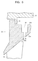
- FIG. 5 to FIG. 7 are views each illustrating a cross section in a vertical direction of a part of an upper half side of the final turbine stage at the steam turbine 10 according to the first embodiment to explain a constitution of another annular slit 40.
- an end part 40a at an upstream side of the annular slit 40 which faces the inner surface 23a of the diaphragm outer ring 23 may be constituted such that, for example, the end part 40a positions on a circumference including an intersection point X between a trailing edge of a blade tip of the stationary blade 26 and the diaphragm outer ring 23. Namely, at the intersection point X, the end part 40a at the upstream side of the annular slit 40, the trailing edge of the blade tip of the stationary blade 26, and the inner surface 23a of the diaphragm outer ring 23 intersect.
- the annular slit 40 is constituted as stated above, and thereby, it is possible to collect the water film before the water film remaining at the intersection point X scatters.
- the end part 40a at the upstream side of the annular slit 40 which faces the inner surface 23a of the diaphragm outer ring 23 may be chamfered.
- chamfering (C chamfering) processing the end part 40a to a corner surface is illustrated, but chamfering (R chamfering) processing the end part 40a to a round surface may be performed.
- FIG. 6 it may be constituted such that an end part at an upstream side of the chamfered surface positions on the circumference including the intersection point X between the trailing edge of the blade tip of the stationary blade 26 and the diaphragm outer ring 23 as same as, for example, the end part 40a at the upstream side of the annular slit 40 illustrated in FIG. 5 .
- the chamfering is performed, and thereby, it is possible to collect the water film remaining at the trailing edge of the blade tip of the stationary blade 26 before the water film scatters.
- an acute angle made up of the turbine rotor axis direction and the inner surface 23a of the diaphragm outer ring 23 where the annular slit 40 is formed is set to be ⁇ .
- An acute angle made up of the turbine rotor axis direction and an inner surface 23c of the diaphragm outer ring 23 at the upstream side than the annular slit 40 is set to be ⁇ .
- the inner surface 23a may be constituted such that the acute angle ⁇ becomes smaller than the acute angle ⁇ .
- expansion of the inner surface 23a of the diaphragm outer ring 23 where the annular slit 40 is formed toward downstream side is smaller than expansion of the inner surface 23c of the diaphragm outer ring 23 at upstream side than the annular slit 40 toward downstream side.
- the acute angle ⁇ is illustrated by, for example, an angle made up of the turbine rotor axis direction and the inner surface 23a at the end part 40a at the upstream side of the annular slit 40 facing the inner surface 23a of the diaphragm outer ring 23 as illustrated in FIG. 7 .
- the inner surface 23a of the diaphragm outer ring 23 where the annular slit 40 is formed may be constituted such that the acute angle ⁇ becomes "0" (zero).
- the inner surface 23a is in parallel to the turbine rotor axis direction, and therefore, a process when the annular slit 40 is formed becomes easy.
- FIG. 8 is a view illustrating a cross section in a vertical direction of a part of an upper half side of the final turbine stage at the steam turbine 10 according to the first embodiment to explain a constitution of another stationary blade 26.
- the trailing edge may be gradually extended as it goes to a blade tip 26b.
- an end part 90a at a downstream side of an extending part 90 made up by extending the trailing edge may be constituted so as to intersect with the end part 40a at the upstream side of the annular slit 40 facing the inner surface 23a of the diaphragm outer ring 23.
- a reason why a range of the part where the extending part 90 is formed is set to be 90% or more of the blade height from the blade root is that the wetness exceeds 0.1 (10%) at 90% or more of the blade height as illustrated in FIG. 13 .
- the wetness exceeds 0.1 (10%) at 90% or more of the blade height as illustrated in FIG. 13 As a result of an internal observation of an actual operating steam turbine, it turns out that formations of the water film and waterway become remarkable when the wetness exceeds 0.1.
- the extending part 90 is included, and thereby, it is possible to collect the water film before the water film remaining at the end part 90a at the downstream side of the extending part 90 scatters.
- annular slit 40 and the communications holes 50 are provided for one stage between the stationary blade 26 and the rotor blade 22 , but the constitution is not limited thereto.
- the annular slit 40 and the communication holes 50 may be, for example, included in plural stages in the turbine rotor axis direction between the stationary blade 26 and the rotor blade 22.
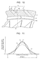
- FIG. 9 is a view illustrating a cross section in a vertical direction of an upper half side of a final turbine stage in a steam turbine 11 according to a second embodiment.
- FIG. 10 is a view illustrating a B-B cross section in FIG. 9 . Note that the same reference symbols are added for the same components as the constitution of the steam turbine 10 according to the first embodiment, and redundant descriptions are not given or simplified.
- a constitution is the same as the constitution of the steam turbine 10 according to the first embodiment except a constitution of a communication hole.
- the communication hole is mainly described.
- a communication hole 51 inclines relative to a radial line R extending from the center axis of the turbine rotor 21 in the radial direction at a cross section perpendicular to the turbine rotor axis direction.
- This inclination direction is not particularly limited, but it is preferably a reverse direction to a turning direction of the steam passing through the stationary blade 26 so as to suppress the flowing of the steam into the communication hole 51.
- the communication hole 51 is preferably formed by, for example, a round hole in which a shape at a cross section perpendicular to a center axis O becomes a circle.
- An inclination angle ⁇ being an acute angle made up of the center axis O of the communication hole 51 and the radial line R is preferably more than "0" (zero) degree and 75 degrees or less.
- the inclination angle ⁇ is set to be more than "0" (zero) degree, and thereby, a communication area between the communication hole 51 and the annular slit 40 increases, and an opening area in the circumferential direction directly sucking the water film and the water droplets from the annular slit 40 increases. Accordingly, it is possible to surely collect the water droplets and the water film dispersed in the circumferential direction.
- a more preferable range of the inclination angle ⁇ is 30 degrees or more and 75 degrees or less.
- a value of P/(D ⁇ sec ⁇ ) is "5" or less, an effect sucking the water film and the water droplets is obtained in the circumferential direction without pause even if the inclination angle ⁇ is less than 30 degrees.
- a lower limit value of the P/(D ⁇ sec ⁇ ) is preferably approximately two to maintain strength of the diaphragm outer ring 23 at a part where the communication hole 51 is not provided, and because a ratio sucking not only the water droplets but also the accompanying main stream increases when a hole area is excessive.
- the expression (1) is satisfied, and thereby, it is possible to surely collect the water droplets and the water film dispersed in the circumferential direction. Besides, it is preferable to satisfy a relationship of the following expression (2) in addition to the expression (1) to enable a more surely collection of the water droplets and the water film.
- L is a groove depth (refer to FIG. 10 ) of the annular slit 40 in the radial direction
- W is a groove width (refer to FIG. 9 ) of the annular slit 40 in the turbine rotor axis direction.
- L/W When a value of L/W is three or more, it is possible to surely collect the water droplets and the water film dispersed in the circumferential direction.
- a maximum value of the L/W is, for example, approximately 20 from a paint of view of reducing an abrasion cost of a lathe cutter which processes the groove.
- the grove width W is preferably 10 mm or less in consideration of application for an actual product, a size of the groove depth L, and so on.
- FIG. 11 is a view illustrating a circumferential distribution of a suction velocity in the radial direction at an inlet of the annular slit 40. Note that the inlet of the annular slit 40 positions at the steam passage 27 side.
- FIG. 11 illustrates the circumferential distribution within a range of the pitch P in the circumferential direction of the communication hole 51 centering on the communication hole 51.
- results illustrated in FIG. 11 are results obtained by a computational fluid analysis.
- the communication hole 51 was formed by the round hole, the P/D was set to be 10, and the inclination angle ⁇ of the communication hole 51 was set to be 60 degrees.
- the L/W it was two in F1, it was three in F2, it was eight in F3, and it was 16 in F4.
- the annular slit 40 is included along the circumferential direction, and the inclination angle ⁇ of the communication hole 51 relative to the radial line R is set to be within the above-stated range, and thereby, it is possible to surely collect the water droplets and the water film dispersed in the circumferential direction. It is thereby possible to suppress the erosion caused by the collision of the water droplets with the rotor blade 22 at the immediate downstream side of the stationary blade 26 and the lowering of the turbine efficiency. Besides, the value of the L/W is set to be within the above-stated range, and thereby, it is possible to more surely collect the water droplets and the water film dispersed in the circumferential direction.
Landscapes
- Engineering & Computer Science (AREA)
- Mechanical Engineering (AREA)
- General Engineering & Computer Science (AREA)
- Turbine Rotor Nozzle Sealing (AREA)
Applications Claiming Priority (1)
| Application Number | Priority Date | Filing Date | Title |
|---|---|---|---|
| JP2013134449A JP6125351B2 (ja) | 2013-06-27 | 2013-06-27 | 蒸気タービン |
Publications (3)
| Publication Number | Publication Date |
|---|---|
| EP2840233A2 true EP2840233A2 (de) | 2015-02-25 |
| EP2840233A3 EP2840233A3 (de) | 2015-12-02 |
| EP2840233B1 EP2840233B1 (de) | 2017-03-15 |
Family
ID=51162458
Family Applications (1)
| Application Number | Title | Priority Date | Filing Date |
|---|---|---|---|
| EP14174843.4A Active EP2840233B1 (de) | 2013-06-27 | 2014-06-27 | Dampfturbine |
Country Status (4)
| Country | Link |
|---|---|
| US (1) | US9850781B2 (de) |
| EP (1) | EP2840233B1 (de) |
| JP (1) | JP6125351B2 (de) |
| KR (1) | KR101578176B1 (de) |
Families Citing this family (6)
| Publication number | Priority date | Publication date | Assignee | Title |
|---|---|---|---|---|
| DE102015218493A1 (de) | 2015-09-25 | 2017-03-30 | Siemens Aktiengesellschaft | Niederdrucksystem und Dampfturbine |
| KR102739479B1 (ko) * | 2019-12-11 | 2024-12-05 | 미츠비시 파워 가부시키가이샤 | 터빈 정익, 터빈 정익 조립체, 및 증기 터빈 |
| CN115768967B (zh) * | 2020-09-28 | 2025-07-11 | 三菱重工业株式会社 | 蒸汽涡轮 |
| US20230323780A1 (en) * | 2020-09-28 | 2023-10-12 | Mitsubishi Heavy Industries, Ltd. | Steam turbine |
| CN114087041B (zh) * | 2021-10-30 | 2024-05-28 | 中国长江动力集团有限公司 | 一种汽轮机除湿级隔板 |
| JP7756748B1 (ja) | 2024-05-01 | 2025-10-20 | 三菱重工業株式会社 | 静翼セグメント、及びこれを備える蒸気タービン |
Family Cites Families (26)
| Publication number | Priority date | Publication date | Assignee | Title |
|---|---|---|---|---|
| DE1576982B1 (de) | 1967-07-04 | 1970-12-23 | Siemens Ag | Leitschaufelkranz mit Einrichtungen zum Absaugen von Kondenswasser in Dampfturbinen |
| JPS54153908A (en) * | 1978-05-26 | 1979-12-04 | Toshiba Corp | Nozzle diaphragm |
| JPS5560404U (de) * | 1978-10-19 | 1980-04-24 | ||
| JPS5641101U (de) * | 1979-09-10 | 1981-04-16 | ||
| JPS61265305A (ja) * | 1985-05-21 | 1986-11-25 | Toshiba Corp | 蒸気タ−ビン |
| JP2573197B2 (ja) * | 1987-01-14 | 1997-01-22 | 株式会社東芝 | 蒸気タ−ビン |
| US4948335A (en) | 1988-12-30 | 1990-08-14 | Westinghouse Electric Corp. | Turbine moisture removal system |
| JP3630740B2 (ja) * | 1994-12-08 | 2005-03-23 | 株式会社東芝 | 蒸気タービンのドレン排出装置 |
| US5494405A (en) * | 1995-03-20 | 1996-02-27 | Westinghouse Electric Corporation | Method of modifying a steam turbine |
| JP2000145404A (ja) * | 1998-11-10 | 2000-05-26 | Hitachi Ltd | 蒸気タービンの湿分飛散防止構造 |
| US6375417B1 (en) * | 2000-07-12 | 2002-04-23 | General Electric Company | Moisture removal pocket for improved moisture removal efficiency |
| JP2002250205A (ja) | 2001-02-21 | 2002-09-06 | Hitachi Ltd | 蒸気タービンの水滴除去構造 |
| JP2004124751A (ja) | 2002-09-30 | 2004-04-22 | Toshiba Corp | 蒸気タービンの湿分分離装置 |
| JP2005113696A (ja) | 2003-10-03 | 2005-04-28 | Hitachi Ltd | 蒸気タービンの湿分分離構造 |
| JP4886271B2 (ja) * | 2005-10-31 | 2012-02-29 | 株式会社東芝 | 蒸気タービンおよびその親水性コーティング材料 |
| US20070292265A1 (en) * | 2006-06-14 | 2007-12-20 | General Electric Company | System design and cooling method for LP steam turbines using last stage hybrid bucket |
| US7789618B2 (en) * | 2006-08-28 | 2010-09-07 | General Electric Company | Systems for moisture removal in steam turbine engines |
| DE102008055824B4 (de) | 2007-11-09 | 2016-08-11 | Alstom Technology Ltd. | Dampfturbine |
| JP2010013782A (ja) | 2008-07-07 | 2010-01-21 | Etsuko Iriya | 帽子又は容器になるシート |
| EP2224096A1 (de) * | 2009-02-27 | 2010-09-01 | Alstom Technology Ltd | Dampfturbine und Verfahren zur Extraktion von Feuchtigkeit aus einer Dampfturbine |
| JP2010216321A (ja) | 2009-03-16 | 2010-09-30 | Hitachi Ltd | 蒸気タービンの動翼及びそれを用いた蒸気タービン |
| JP5023125B2 (ja) * | 2009-09-28 | 2012-09-12 | 株式会社日立製作所 | 軸流タービン |
| JP5653659B2 (ja) | 2010-06-17 | 2015-01-14 | 三菱重工業株式会社 | 蒸気タービンの車室構造 |
| JP5603800B2 (ja) * | 2011-02-22 | 2014-10-08 | 株式会社日立製作所 | タービン静翼、およびそれを用いた蒸気タービン設備 |
| JP5823305B2 (ja) * | 2012-01-19 | 2015-11-25 | 株式会社東芝 | 蒸気タービンおよび蒸気タービンの動翼 |
| JP5968173B2 (ja) * | 2012-09-14 | 2016-08-10 | 三菱日立パワーシステムズ株式会社 | 蒸気タービン静翼及び蒸気タービン |
-
2013
- 2013-06-27 JP JP2013134449A patent/JP6125351B2/ja active Active
-
2014
- 2014-06-25 KR KR1020140078184A patent/KR101578176B1/ko active Active
- 2014-06-26 US US14/315,837 patent/US9850781B2/en active Active
- 2014-06-27 EP EP14174843.4A patent/EP2840233B1/de active Active
Non-Patent Citations (1)
| Title |
|---|
| None |
Also Published As
| Publication number | Publication date |
|---|---|
| KR101578176B1 (ko) | 2015-12-16 |
| EP2840233A3 (de) | 2015-12-02 |
| KR20150001660A (ko) | 2015-01-06 |
| US20150003969A1 (en) | 2015-01-01 |
| EP2840233B1 (de) | 2017-03-15 |
| JP6125351B2 (ja) | 2017-05-10 |
| JP2015010482A (ja) | 2015-01-19 |
| US9850781B2 (en) | 2017-12-26 |
Similar Documents
| Publication | Publication Date | Title |
|---|---|---|
| EP2840233A2 (de) | Dampfturbine | |
| US6435819B2 (en) | Turbo machines | |
| US3832089A (en) | Turbomachinery and method of manufacturing diffusers therefor | |
| CN101403321B (zh) | 轴流式涡轮机以及轴流式涡轮机级结构 | |
| CN105934615B (zh) | 密封构造及旋转机械 | |
| JP2009156122A (ja) | 遠心圧縮機用インペラ | |
| US9982539B2 (en) | Turbomachines having guide ducts | |
| CN105782117A (zh) | 一种离心压缩机扩稳装置 | |
| JP2009057959A (ja) | 遠心圧縮機とその羽根車およびその運転方法 | |
| EP3012409B1 (de) | Turbinenanordnung | |
| JP5023125B2 (ja) | 軸流タービン | |
| US11028695B2 (en) | Steam turbine | |
| EP2226471B1 (de) | Arbeitsmediumsentnahme für Axialturbine | |
| RU2567524C2 (ru) | Система и способ для отбора рабочей текучей среды от внутреннего объема турбомашины и турбомашина, содержащая такую систему | |
| JP2015048716A (ja) | 蒸気タービン | |
| JP2010190149A (ja) | 遠心圧縮機 | |
| JP2018135836A (ja) | 遠心圧縮機 | |
| JP5651532B2 (ja) | 蒸気タービン | |
| JP2017008756A (ja) | 軸流タービン | |
| JP6362984B2 (ja) | 遠心型流体機械 | |
| US9945238B2 (en) | Steam turbine | |
| JP2016135998A (ja) | 蒸気タービン | |
| JP2016075204A (ja) | 遠心圧縮機及び遠心圧縮機の設計方法 | |
| JP5677332B2 (ja) | 蒸気タービン | |
| US9644483B2 (en) | Turbomachine bucket having flow interrupter and related turbomachine |
Legal Events
| Date | Code | Title | Description |
|---|---|---|---|
| PUAI | Public reference made under article 153(3) epc to a published international application that has entered the european phase |
Free format text: ORIGINAL CODE: 0009012 |
|
| 17P | Request for examination filed |
Effective date: 20140627 |
|
| AK | Designated contracting states |
Kind code of ref document: A2 Designated state(s): AL AT BE BG CH CY CZ DE DK EE ES FI FR GB GR HR HU IE IS IT LI LT LU LV MC MK MT NL NO PL PT RO RS SE SI SK SM TR |
|
| AX | Request for extension of the european patent |
Extension state: BA ME |
|
| PUAL | Search report despatched |
Free format text: ORIGINAL CODE: 0009013 |
|
| AK | Designated contracting states |
Kind code of ref document: A3 Designated state(s): AL AT BE BG CH CY CZ DE DK EE ES FI FR GB GR HR HU IE IS IT LI LT LU LV MC MK MT NL NO PL PT RO RS SE SI SK SM TR |
|
| AX | Request for extension of the european patent |
Extension state: BA ME |
|
| RIC1 | Information provided on ipc code assigned before grant |
Ipc: F01D 25/32 20060101ALI20151023BHEP Ipc: F01D 9/04 20060101AFI20151023BHEP Ipc: F01D 1/00 20060101ALN20151023BHEP |
|
| RIC1 | Information provided on ipc code assigned before grant |
Ipc: F01D 25/32 20060101ALI20160713BHEP Ipc: F01D 9/04 20060101AFI20160713BHEP Ipc: F01D 1/00 20060101ALN20160713BHEP |
|
| GRAP | Despatch of communication of intention to grant a patent |
Free format text: ORIGINAL CODE: EPIDOSNIGR1 |
|
| INTG | Intention to grant announced |
Effective date: 20161004 |
|
| STAA | Information on the status of an ep patent application or granted ep patent |
Free format text: STATUS: GRANT OF PATENT IS INTENDED |
|
| GRAS | Grant fee paid |
Free format text: ORIGINAL CODE: EPIDOSNIGR3 |
|
| GRAA | (expected) grant |
Free format text: ORIGINAL CODE: 0009210 |
|
| STAA | Information on the status of an ep patent application or granted ep patent |
Free format text: STATUS: THE PATENT HAS BEEN GRANTED |
|
| AK | Designated contracting states |
Kind code of ref document: B1 Designated state(s): AL AT BE BG CH CY CZ DE DK EE ES FI FR GB GR HR HU IE IS IT LI LT LU LV MC MK MT NL NO PL PT RO RS SE SI SK SM TR |
|
| REG | Reference to a national code |
Ref country code: CH Ref legal event code: EP Ref country code: GB Ref legal event code: FG4D |
|
| REG | Reference to a national code |
Ref country code: IE Ref legal event code: FG4D |
|
| REG | Reference to a national code |
Ref country code: CH Ref legal event code: NV Representative=s name: SERVOPATENT GMBH, CH |
|
| REG | Reference to a national code |
Ref country code: AT Ref legal event code: REF Ref document number: 875812 Country of ref document: AT Kind code of ref document: T Effective date: 20170415 |
|
| REG | Reference to a national code |
Ref country code: DE Ref legal event code: R096 Ref document number: 602014007519 Country of ref document: DE |
|
| REG | Reference to a national code |
Ref country code: NL Ref legal event code: MP Effective date: 20170315 |
|
| REG | Reference to a national code |
Ref country code: LT Ref legal event code: MG4D |
|
| PG25 | Lapsed in a contracting state [announced via postgrant information from national office to epo] |
Ref country code: HR Free format text: LAPSE BECAUSE OF FAILURE TO SUBMIT A TRANSLATION OF THE DESCRIPTION OR TO PAY THE FEE WITHIN THE PRESCRIBED TIME-LIMIT Effective date: 20170315 Ref country code: LT Free format text: LAPSE BECAUSE OF FAILURE TO SUBMIT A TRANSLATION OF THE DESCRIPTION OR TO PAY THE FEE WITHIN THE PRESCRIBED TIME-LIMIT Effective date: 20170315 Ref country code: FI Free format text: LAPSE BECAUSE OF FAILURE TO SUBMIT A TRANSLATION OF THE DESCRIPTION OR TO PAY THE FEE WITHIN THE PRESCRIBED TIME-LIMIT Effective date: 20170315 Ref country code: GR Free format text: LAPSE BECAUSE OF FAILURE TO SUBMIT A TRANSLATION OF THE DESCRIPTION OR TO PAY THE FEE WITHIN THE PRESCRIBED TIME-LIMIT Effective date: 20170616 Ref country code: NO Free format text: LAPSE BECAUSE OF FAILURE TO SUBMIT A TRANSLATION OF THE DESCRIPTION OR TO PAY THE FEE WITHIN THE PRESCRIBED TIME-LIMIT Effective date: 20170615 |
|
| REG | Reference to a national code |
Ref country code: AT Ref legal event code: MK05 Ref document number: 875812 Country of ref document: AT Kind code of ref document: T Effective date: 20170315 |
|
| PG25 | Lapsed in a contracting state [announced via postgrant information from national office to epo] |
Ref country code: RS Free format text: LAPSE BECAUSE OF FAILURE TO SUBMIT A TRANSLATION OF THE DESCRIPTION OR TO PAY THE FEE WITHIN THE PRESCRIBED TIME-LIMIT Effective date: 20170315 Ref country code: BG Free format text: LAPSE BECAUSE OF FAILURE TO SUBMIT A TRANSLATION OF THE DESCRIPTION OR TO PAY THE FEE WITHIN THE PRESCRIBED TIME-LIMIT Effective date: 20170615 Ref country code: SE Free format text: LAPSE BECAUSE OF FAILURE TO SUBMIT A TRANSLATION OF THE DESCRIPTION OR TO PAY THE FEE WITHIN THE PRESCRIBED TIME-LIMIT Effective date: 20170315 Ref country code: LV Free format text: LAPSE BECAUSE OF FAILURE TO SUBMIT A TRANSLATION OF THE DESCRIPTION OR TO PAY THE FEE WITHIN THE PRESCRIBED TIME-LIMIT Effective date: 20170315 |
|
| PG25 | Lapsed in a contracting state [announced via postgrant information from national office to epo] |
Ref country code: NL Free format text: LAPSE BECAUSE OF FAILURE TO SUBMIT A TRANSLATION OF THE DESCRIPTION OR TO PAY THE FEE WITHIN THE PRESCRIBED TIME-LIMIT Effective date: 20170315 |
|
| PG25 | Lapsed in a contracting state [announced via postgrant information from national office to epo] |
Ref country code: ES Free format text: LAPSE BECAUSE OF FAILURE TO SUBMIT A TRANSLATION OF THE DESCRIPTION OR TO PAY THE FEE WITHIN THE PRESCRIBED TIME-LIMIT Effective date: 20170315 Ref country code: CZ Free format text: LAPSE BECAUSE OF FAILURE TO SUBMIT A TRANSLATION OF THE DESCRIPTION OR TO PAY THE FEE WITHIN THE PRESCRIBED TIME-LIMIT Effective date: 20170315 Ref country code: AT Free format text: LAPSE BECAUSE OF FAILURE TO SUBMIT A TRANSLATION OF THE DESCRIPTION OR TO PAY THE FEE WITHIN THE PRESCRIBED TIME-LIMIT Effective date: 20170315 Ref country code: SK Free format text: LAPSE BECAUSE OF FAILURE TO SUBMIT A TRANSLATION OF THE DESCRIPTION OR TO PAY THE FEE WITHIN THE PRESCRIBED TIME-LIMIT Effective date: 20170315 Ref country code: EE Free format text: LAPSE BECAUSE OF FAILURE TO SUBMIT A TRANSLATION OF THE DESCRIPTION OR TO PAY THE FEE WITHIN THE PRESCRIBED TIME-LIMIT Effective date: 20170315 Ref country code: RO Free format text: LAPSE BECAUSE OF FAILURE TO SUBMIT A TRANSLATION OF THE DESCRIPTION OR TO PAY THE FEE WITHIN THE PRESCRIBED TIME-LIMIT Effective date: 20170315 Ref country code: IT Free format text: LAPSE BECAUSE OF FAILURE TO SUBMIT A TRANSLATION OF THE DESCRIPTION OR TO PAY THE FEE WITHIN THE PRESCRIBED TIME-LIMIT Effective date: 20170315 |
|
| PG25 | Lapsed in a contracting state [announced via postgrant information from national office to epo] |
Ref country code: IS Free format text: LAPSE BECAUSE OF FAILURE TO SUBMIT A TRANSLATION OF THE DESCRIPTION OR TO PAY THE FEE WITHIN THE PRESCRIBED TIME-LIMIT Effective date: 20170715 Ref country code: PT Free format text: LAPSE BECAUSE OF FAILURE TO SUBMIT A TRANSLATION OF THE DESCRIPTION OR TO PAY THE FEE WITHIN THE PRESCRIBED TIME-LIMIT Effective date: 20170717 Ref country code: SM Free format text: LAPSE BECAUSE OF FAILURE TO SUBMIT A TRANSLATION OF THE DESCRIPTION OR TO PAY THE FEE WITHIN THE PRESCRIBED TIME-LIMIT Effective date: 20170315 Ref country code: PL Free format text: LAPSE BECAUSE OF FAILURE TO SUBMIT A TRANSLATION OF THE DESCRIPTION OR TO PAY THE FEE WITHIN THE PRESCRIBED TIME-LIMIT Effective date: 20170315 |
|
| REG | Reference to a national code |
Ref country code: DE Ref legal event code: R097 Ref document number: 602014007519 Country of ref document: DE |
|
| PLBE | No opposition filed within time limit |
Free format text: ORIGINAL CODE: 0009261 |
|
| STAA | Information on the status of an ep patent application or granted ep patent |
Free format text: STATUS: NO OPPOSITION FILED WITHIN TIME LIMIT |
|
| PG25 | Lapsed in a contracting state [announced via postgrant information from national office to epo] |
Ref country code: DK Free format text: LAPSE BECAUSE OF FAILURE TO SUBMIT A TRANSLATION OF THE DESCRIPTION OR TO PAY THE FEE WITHIN THE PRESCRIBED TIME-LIMIT Effective date: 20170315 Ref country code: MC Free format text: LAPSE BECAUSE OF FAILURE TO SUBMIT A TRANSLATION OF THE DESCRIPTION OR TO PAY THE FEE WITHIN THE PRESCRIBED TIME-LIMIT Effective date: 20170315 |
|
| 26N | No opposition filed |
Effective date: 20171218 |
|
| PG25 | Lapsed in a contracting state [announced via postgrant information from national office to epo] |
Ref country code: SI Free format text: LAPSE BECAUSE OF FAILURE TO SUBMIT A TRANSLATION OF THE DESCRIPTION OR TO PAY THE FEE WITHIN THE PRESCRIBED TIME-LIMIT Effective date: 20170315 |
|
| REG | Reference to a national code |
Ref country code: FR Ref legal event code: ST Effective date: 20180228 |
|
| REG | Reference to a national code |
Ref country code: IE Ref legal event code: MM4A |
|
| PG25 | Lapsed in a contracting state [announced via postgrant information from national office to epo] |
Ref country code: LU Free format text: LAPSE BECAUSE OF NON-PAYMENT OF DUE FEES Effective date: 20170627 Ref country code: IE Free format text: LAPSE BECAUSE OF NON-PAYMENT OF DUE FEES Effective date: 20170627 |
|
| PG25 | Lapsed in a contracting state [announced via postgrant information from national office to epo] |
Ref country code: FR Free format text: LAPSE BECAUSE OF NON-PAYMENT OF DUE FEES Effective date: 20170630 |
|
| REG | Reference to a national code |
Ref country code: BE Ref legal event code: MM Effective date: 20170630 |
|
| PG25 | Lapsed in a contracting state [announced via postgrant information from national office to epo] |
Ref country code: BE Free format text: LAPSE BECAUSE OF NON-PAYMENT OF DUE FEES Effective date: 20170630 |
|
| PG25 | Lapsed in a contracting state [announced via postgrant information from national office to epo] |
Ref country code: MT Free format text: LAPSE BECAUSE OF NON-PAYMENT OF DUE FEES Effective date: 20170627 |
|
| GBPC | Gb: european patent ceased through non-payment of renewal fee |
Effective date: 20180627 |
|
| PG25 | Lapsed in a contracting state [announced via postgrant information from national office to epo] |
Ref country code: GB Free format text: LAPSE BECAUSE OF NON-PAYMENT OF DUE FEES Effective date: 20180627 |
|
| PG25 | Lapsed in a contracting state [announced via postgrant information from national office to epo] |
Ref country code: HU Free format text: LAPSE BECAUSE OF FAILURE TO SUBMIT A TRANSLATION OF THE DESCRIPTION OR TO PAY THE FEE WITHIN THE PRESCRIBED TIME-LIMIT; INVALID AB INITIO Effective date: 20140627 |
|
| PG25 | Lapsed in a contracting state [announced via postgrant information from national office to epo] |
Ref country code: CY Free format text: LAPSE BECAUSE OF FAILURE TO SUBMIT A TRANSLATION OF THE DESCRIPTION OR TO PAY THE FEE WITHIN THE PRESCRIBED TIME-LIMIT Effective date: 20170315 |
|
| PG25 | Lapsed in a contracting state [announced via postgrant information from national office to epo] |
Ref country code: MK Free format text: LAPSE BECAUSE OF FAILURE TO SUBMIT A TRANSLATION OF THE DESCRIPTION OR TO PAY THE FEE WITHIN THE PRESCRIBED TIME-LIMIT Effective date: 20170315 |
|
| PG25 | Lapsed in a contracting state [announced via postgrant information from national office to epo] |
Ref country code: TR Free format text: LAPSE BECAUSE OF FAILURE TO SUBMIT A TRANSLATION OF THE DESCRIPTION OR TO PAY THE FEE WITHIN THE PRESCRIBED TIME-LIMIT Effective date: 20170315 |
|
| REG | Reference to a national code |
Ref country code: CH Ref legal event code: PCAR Free format text: NEW ADDRESS: WANNERSTRASSE 9/1, 8045 ZUERICH (CH) |
|
| PG25 | Lapsed in a contracting state [announced via postgrant information from national office to epo] |
Ref country code: AL Free format text: LAPSE BECAUSE OF FAILURE TO SUBMIT A TRANSLATION OF THE DESCRIPTION OR TO PAY THE FEE WITHIN THE PRESCRIBED TIME-LIMIT Effective date: 20170315 |
|
| PGFP | Annual fee paid to national office [announced via postgrant information from national office to epo] |
Ref country code: CH Payment date: 20230702 Year of fee payment: 10 |
|
| REG | Reference to a national code |
Ref country code: CH Ref legal event code: PL |
|
| PG25 | Lapsed in a contracting state [announced via postgrant information from national office to epo] |
Ref country code: CH Free format text: LAPSE BECAUSE OF NON-PAYMENT OF DUE FEES Effective date: 20240630 |
|
| PGFP | Annual fee paid to national office [announced via postgrant information from national office to epo] |
Ref country code: DE Payment date: 20250402 Year of fee payment: 12 |