EP2840237A2 - Eisschmelzende Vorrichtung für Schiffreisen - Google Patents
Eisschmelzende Vorrichtung für Schiffreisen Download PDFInfo
- Publication number
- EP2840237A2 EP2840237A2 EP20140166147 EP14166147A EP2840237A2 EP 2840237 A2 EP2840237 A2 EP 2840237A2 EP 20140166147 EP20140166147 EP 20140166147 EP 14166147 A EP14166147 A EP 14166147A EP 2840237 A2 EP2840237 A2 EP 2840237A2
- Authority
- EP
- European Patent Office
- Prior art keywords
- thermal medium
- ship
- unit
- melting apparatus
- heated
- Prior art date
- Legal status (The legal status is an assumption and is not a legal conclusion. Google has not performed a legal analysis and makes no representation as to the accuracy of the status listed.)
- Withdrawn
Links
Images


Classifications
-
- B—PERFORMING OPERATIONS; TRANSPORTING
- B63—SHIPS OR OTHER WATERBORNE VESSELS; RELATED EQUIPMENT
- B63B—SHIPS OR OTHER WATERBORNE VESSELS; EQUIPMENT FOR SHIPPING
- B63B35/00—Vessels or similar floating structures specially adapted for specific purposes and not otherwise provided for
- B63B35/08—Ice-breakers or other vessels or floating structures for operation in ice-infested waters; Ice-breakers, or other vessels or floating structures having equipment specially adapted therefor
- B63B35/12—Ice-breakers or other vessels or floating structures for operation in ice-infested waters; Ice-breakers, or other vessels or floating structures having equipment specially adapted therefor having ice-cutters
-
- B—PERFORMING OPERATIONS; TRANSPORTING
- B63—SHIPS OR OTHER WATERBORNE VESSELS; RELATED EQUIPMENT
- B63B—SHIPS OR OTHER WATERBORNE VESSELS; EQUIPMENT FOR SHIPPING
- B63B59/00—Hull protection specially adapted for vessels; Cleaning devices specially adapted for vessels
-
- B—PERFORMING OPERATIONS; TRANSPORTING
- B63—SHIPS OR OTHER WATERBORNE VESSELS; RELATED EQUIPMENT
- B63J—AUXILIARIES ON VESSELS
- B63J2/00—Arrangements of ventilation, heating, cooling, or air-conditioning
- B63J2/12—Heating; Cooling
-
- F—MECHANICAL ENGINEERING; LIGHTING; HEATING; WEAPONS; BLASTING
- F01—MACHINES OR ENGINES IN GENERAL; ENGINE PLANTS IN GENERAL; STEAM ENGINES
- F01K—STEAM ENGINE PLANTS; STEAM ACCUMULATORS; ENGINE PLANTS NOT OTHERWISE PROVIDED FOR; ENGINES USING SPECIAL WORKING FLUIDS OR CYCLES
- F01K13/00—General layout or general methods of operation of complete plants
-
- F—MECHANICAL ENGINEERING; LIGHTING; HEATING; WEAPONS; BLASTING
- F01—MACHINES OR ENGINES IN GENERAL; ENGINE PLANTS IN GENERAL; STEAM ENGINES
- F01K—STEAM ENGINE PLANTS; STEAM ACCUMULATORS; ENGINE PLANTS NOT OTHERWISE PROVIDED FOR; ENGINES USING SPECIAL WORKING FLUIDS OR CYCLES
- F01K15/00—Adaptations of plants for special use
- F01K15/02—Adaptations of plants for special use for driving vehicles, e.g. locomotives
- F01K15/04—Adaptations of plants for special use for driving vehicles, e.g. locomotives the vehicles being waterborne vessels
Definitions
- the present invention relates to an ice melting apparatus for a ship voyage which is configured to be able to sail across a sea, a lake, or a river while melting ice of a sea, a lake, or a river.
- An ice breaker is a ship developed only to sail across a sea area covered with ice and improves a sea route by breaking ice.
- a known speed of the ice breaker is about 2.5 knot on average which is about 20 % of about 12 knot which is an average speed of a large merchant ship which sails across a general sea area without ice. Therefore, in spite of the reduced distance, the sailing time is suddenly increased and thus economic feasibility is reduced.
- Korean Patent Laid-Open Publication No. 2012-53292 discloses that a heating member in which high-pressure steam flows is mounted at a bow part of a ship.
- the method of using steam has a problem in that a structure of various kinds of pipes and valves is complicated and costs are increased to resist a high pressure and much time is required to melt ice due to small heat capacity.
- the present invention has been made in an effort to provide an apparatus simply mounted in a sailing ship to remove ice at a low cost and high efficiency without using an ice breaker.
- the present invention has been made in an effort to provide an ice melting apparatus for a ship voyage which is configured to rapidly melt ice just by an instant contact with ice using thermal medium oil, instead of breaking ice.
- an ice melting apparatus for a ship voyage including: a boiler configured to heat a thermal medium; a high temperature pump configured to transfer the heated thermal medium; a heating cover unit configured to be heated by the thermal medium transferred by the high temperature pump and attached to a bow part of a ship; and a hot gas jet unit configured to be disposed in front of the heating cover unit and jet the air heated by the thermal medium.
- the high temperature pump may include a motor part and an impeller part which allows the motor part to transfer the thermal medium and the thermal medium may be configured to be circulated into the motor part.
- the heating cover unit may have a metal pad form having a blade shape meeting left and right surfaces of the bow part and an inside of the heating cover unit may be provided with a first heat exchange to be heat-exchanged with the thermal medium.
- the ice melting apparatus for a ship voyage may further include: a heat insulating pad configured to be disposed at a contact portion with the bow part of the heating cover unit and block heat from the heating cover unit.
- the ice melting apparatus for a ship voyage may further include: an extending frame configured to extend from the bow part to the hot gas jet unit to support the hot gas jet unit.
- the extending frame may be provided with a buffer part which is configured to buffer the hot gas jet unit.
- the hot gas jet unit may be disposed in a cross direction with respect to a progress direction of the ship.
- the hot gas jet unit may include: a compressor configured to transfer air; a second heat exchange part configured to allow the thermal medium to heat the air; and a plurality of nozzles configured to rapidly jet the heated air.
- the ice melting apparatus for a ship voyage may further include: a heating knife unit configured to have a blade form vertically disposed in front of the heating cover unit and be heated by the thermal medium to melt ice.
- the heating knife unit may be provided with a third heat exchange part to be heat-exchanged with the thermal medium.
- the ice melting apparatus for a ship voyage may further include: a position control unit configured to control a posture and a depth of the heating knife unit.
- the thermal medium may be oils which transfer heat at a temperature of 250 to 450 °C.
- an ice melting apparatus for a ship voyage, including: a boiler configured to heat a thermal medium; a high temperature pump configured to transport the heated thermal medium; a heating cover unit configured to be heated by a thermal medium transported by the high temperature pump and attached to a bow part of a ship; and a heating knife unit configured to have a blade form vertically disposed in front of the heating cover unit and be heated by the thermal medium to melt ice.
- an ice melting apparatus for a ship voyage, including: a boiler configured to heat a thermal medium; a high temperature pump configured to transport the heated thermal medium; a hot gas jet unit configured to be heated by the thermal medium transferred by the high temperature pump and disposed in front of a bow part of a ship to inject air heated by the thermal medium; and a heating knife unit configured to have a blade form vertically disposed in front of the hot gas jet unit and be heated by the thermal medium to melt ice.
- FIG. 1 is a perspective view conceptually illustrating a state in which ice is being melted by a ship S equipped with an ice melting apparatus 100 for a ship voyage according to an exemplary embodiment of the present invention
- FIG. 2 is a transversal cross-sectional view conceptually illustrating a state in which ice is being melted by the ship S equipped with the ice melting apparatus 100 for a ship voyage according to the exemplary embodiment of the present invention
- FIG. 3 is a configuration diagram of the ice melting apparatus 100 for a ship voyage according to the exemplary embodiment of the present invention
- FIG. 4 is a partial plan cross-sectional view of a state in which a heating cover unit 110 according to an exemplary embodiment of the present invention is mounted
- FIG. 5 is a schematic plan cross-sectional view of a hot gas jet unit 120 according to an exemplary embodiment of the present invention.
- the ice melting apparatus 100 for a ship voyage is configured to be attached to a bow part of the ship S and may be operated in a state in which the ice melting apparatus 100 for a ship voyage may be mounted in a sea area with ice and in a state in which the ice melting apparatus 100 for a ship voyage may be detached in a general sea area without ice.
- the ice melting apparatus 100 for a ship voyage largely includes a heating cover unit 110, a hot gas jet unit 120, and a heating knife unit 130, in which these heating parts are connected to a boiler 150 and a high temperature pump 160 which are mounted in the ship S.
- the ice melting apparatus 100 for a ship voyage may be configured to include any one or a combination of two of the heating cover unit 110, the hot gas jet unit 120, and the heating knife unit 130, instead of being configured to include all of the ice melting apparatus 100 for a ship voyage.
- the boiler 150 is configured to be able to heat a thermal medium.
- a thermal medium mineral oils which may transfer heat at a temperature of 250 to 450 °C may be used and provide a sufficient heat capacity to melt ice while keeping a liquid state even at a high temperature.
- the thermal medium heated by the boiler 150 is supplied to the high temperature pump 160 via a first valve 171.
- the high temperature pump 160 is a part which circulates the high temperature thermal medium and is required to prevent the thermal medium from being leaked, keep insulation and apply a high pressure.
- the high temperature pump 160 will be described below in detail with reference to FIG. 6 .
- the heating cover unit 110 is configured to be heated by the thermal medium transferred by the high temperature pump 160 and is configured to be attached to the bow part of the ship S. In detail, as illustrated in FIG. 4 .
- the heating cover unit 110 may have a metal pad form having a blade shape meeting left and right surfaces of the bow part.
- An inside of the heating cover unit 110 may be provided with a first heat exchange part 112 to be heat-exchanged with the thermal medium.
- the form of the first heat exchange part 112 may be configured in a form of a plurality of tubes or a plurality of layers in which the heat exchange is easily performed.
- a contact portion with the bow part of the heating cover unit 110 may be provided with a heat insulating pad 115.
- the heat insulating pad 115 is configured to prevent the bow part from being subjected to heat degeneration or fatigue due to the high temperature heating cover unit 110 which is heated at about 250 °C by being heat-exchanged with the thermal medium of 250 to 450 °C.
- the heat insulating pad 115 may be made of elastic resin, rubber, or a spring material to be able to reduce an impact due to the collision with ice C which is transferred to a ship body.
- the hot gas jet unit 120 is disposed in front of the heating cover unit 110 and is configured to be able to jet air heated by the thermal medium.
- the hot gas jet unit 120 may be provided with an extending frame 141, which extends from the bow part of the ship S to the hot gas jet unit 120, so as to support the hot gas jet unit 120.
- the extending frame 141 may be provided with a buffer part 142 to allow the hot gas jet unit 120 or the heating knife unit 130 to reduce resistance or impact force which is applied by the collision with the ice C.
- the buffer unit 142 may be formed of an elastic sprint, an operating fluid type cylinder, and the like.
- the hot gas jet unit 120 is disposed to a cross direction with respect to a progress direction of the ship S (see FIG. 1 ) and the inside thereof is provided with a second heat exchange part 122 which is formed to enable the thermal medium to heat air.
- the hot gas jet unit 120 may include a compressor 125 to provide compressed air (see FIG. 3 ) and a lower surface of the hot gas jet unit 120 may be provided with a plurality of nozzles 121 which are formed to jet the heated air toward ice at a high speed (see FIG. 5 ).
- the heating knife unit 130 has a blade form vertically disposed in front of the heating cover unit 110 and is heated by the thermal medium to melt ice having a thickness of about 5 to 7 m.
- the inside of the heating knife unit 130 may be provided with a third heat exchange part 132 to be heat exchanged with the thermal medium.
- a position control unit 135 to control a posture and a depth of the heating knife unit 13 depending on a thickness or a depth of ice may be disposed between the hot gas jet unit 120 and the heating knife unit 130.
- the ship S may be provided with a crane 101 and a cable 102.
- the heating knife unit 130 disposed at a bow part is heated at about 250 °C by the thermal medium heated at a high temperature of 250 to 450 °C.
- the heating knife unit 130 having the blade form provides a large amount of heat to the ice C for a short period of time when both sides of the heating knife unit 130 contact the ice C so as to be rapidly heated at 0 °C which is a temperature at which the ice C may be melted. Therefore, a widely expansive ice layer is broken.
- the hot gas jet unit 120 rapidly jets the high temperature air heated at about 250 °C by the thermal medium to the ice C. Therefore, the ice C is formed to be easily broken into small pieces.
- the heating cover unit 110 helps the ice melted by the heating knife unit 130 or the hot gas jet unit 120, which is disposed in front of the heating cover unit 110, to be completely separated. However, at the time of combining the heating cover unit 110, the hot gas jet unit 120, and the heating knife unit 130, any one of them may be omitted. Further, as illustrated in FIG. 3 , a heating means to melt ice may be selectively used by a second value 172 to open and close the thermal medium supplied to the heating cover unit 110 and a third valve 173 to open and close the thermal medium supplied to the hot gas jet unit 120 or the heating knife unit 130.
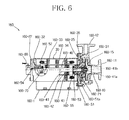
- FIG. 6 is a cross-sectional view of a high temperature pump 160 according to an exemplary embodiment of the present invention.
- the high temperature pump 160 which is a high heat resistance pump capable of resisting a high temperature
- a non-sealed canned motor pump in which a seal ring is not damaged even in an excessive environment may be used. That is, the high temperature pump 160 may include a motor part and an impeller part, and a thermal medium is configured to be circulated to an inner portion of the motor part.
- the high temperature pump 160 will be described in more detail.
- the high temperature pump 160 may include components such as a casing 160-10, an impeller 160-15, a front housing 160-12, a rear housing 160-22, a stator unit 160-30, a rotor assembly 160-40, bearings 160-51 and 160-52, sleeves 160-55 and 160-56, an auxiliary impeller 160-60, a connector 160-70, and the like. However, in some cases, the high temperature pump 160 does not include some of the above-mentioned components or may be replaced by another form.
- the casing 160-10 which is a component enclosing the impeller 160-15, is provided with an inlet 111 to which an operating fluid, that is, the liquid thermal medium is input and an outlet 112 transferring the operating fluid by a centrifugal force.
- the impeller 160-15 which is a component coupled to the rotor assembly 160-40, receives a driving force provided from the rotor assembly 160-40 and forcibly guides the operating fluid in a centrifugal direction by rotation to allow the operating fluid to move toward the outlet 112 of the casing 160-10.
- the front housing 160-21 and the rear housing 160-22 are formed in a form in which they are extended inwardly, respectively, so as to provide seats on which the bearings 160-51 and 160-52 are to be seated.
- the stator unit 160-30 is provided with the respective flanges 160-31 and 160-32.
- the front flange 131 may be formed in a form in which it has a diameter larger than that of the rear flange 132 so as to be directly coupled to the casing 160-10.
- the front flange 131 and the casing 160-10 are coupled to each other by a flange bolt 135 inserted from the front flange 131 side.
- a high sealing force and the assembling simplification is performed by a direct coupling structure between the stator unit 160-30 and the casing 160-10.
- the front housing 160-21 is coupled to the front flange 131 of the stator unit 160-30 by a flange bolt 125 inserted from the front housing 160-21 side.
- the rotor assembly 160-40 includes a shaft 160-41, a rotor core 160-42 fixed to the shaft 160-41, and a rotor can 143 sealing the rotor core 160-42.
- the shaft 160-41 includes a through-hole 160-41a formed in a length direction at the center thereof and includes a side hole 160-41b connected to the through-hole 160-41a and formed in a radial direction.
- the operating fluid is introduced into the through-hole 160-41a by an action of the impeller 160-15 and is then introduced into an internal space of the motor through the side hole 160-41b.
- a front end and a rear end of the rotor assembly 160-40 are fitted by the sleeves 160-53 and 160-54, respectively, and the sleeves 160-53 and 160-54 are supported by the respective bearings 160-51 and 160-52.
- the bearings 160-51 and 160-52 include a labyrinth 160-51a formed in spiral and axial directions, and smooth sliding between the shaft 160-41 and the bearings 160-51 and 160-52 is generated by the operating fluid moved along the labyrinth 160-51a. Therefore, a lubricating action is implemented by the thermal medium, which is the operating fluid transferred by a pump, without using a separate lubricating oil. Therefore, since a seal ring, or the like, is not used for a period in which the high temperature pump 160 is operated, leakage of the thermal medium due to breakage of the seal ring does not occur.
- the stator unit 160-30 has a form in which an electric wire is wound around an iron core 160-33 and is sealed by a stator can 160-34.
- a front end portion and a rear end portion of the stator unit 160-30 are provided with the flanges 160-31 and 160-32 so as to be coupled to the front housing 160-21 and the rear housing 160-32, respectively, as described above.
- the auxiliary impeller 160-60 provides a passage for discharging an air included in an internal space in which the rotor assembly 160-40 is mounted. That is, the auxiliary impeller 160-60 discharges the air so that the operating fluid is introduced into the internal space by rotation of the impeller 160-15 after the heat exchange type cooling apparatus for a transformer is operated and is closed when the air is completely discharged.
- the connector 160-70 which is a component connecting the electric wire, or the like, of the stator unit 160-30 to an external terminal, is spaced apart from a high temperature stator unit 160-30 by a predetermined distance by an extension tube.
- the seal ring may not be damaged and durability may be increased.
- ice may be sequentially melted using the thermal medium having high heat capacity supplied to the high temperature pump, instead of breaking ice, thereby rapidly melting ice and since there is no need to use the thick steel plate to resist the collision with ice and crush ice, the relatively cheaper and higher-efficiency apparatus may be configured. Therefore, it is possible to save huge energy required to bypass the sea area with ice.
- the sealing may be kept under the vibration or the high temperature environment by applying the canned motor type having the structure in which the thermal medium is circulated in the high temperature pump, thereby stably displaying the performance even in the extreme environment.
- the ice melting apparatus for a ship voyage as described above are not restrictively applied to the configuration and the method of the exemplary embodiments described above. All or some of the above-mentioned exemplary embodiments may also be selectively combined with each other so that various modifications may be made.
Landscapes
- Engineering & Computer Science (AREA)
- Chemical & Material Sciences (AREA)
- Combustion & Propulsion (AREA)
- Mechanical Engineering (AREA)
- Ocean & Marine Engineering (AREA)
- General Engineering & Computer Science (AREA)
- Structures Of Non-Positive Displacement Pumps (AREA)
- Air Supply (AREA)
Applications Claiming Priority (1)
| Application Number | Priority Date | Filing Date | Title |
|---|---|---|---|
| KR20130089298A KR101326081B1 (ko) | 2013-07-29 | 2013-07-29 | 선박 항해용 해빙 장치 |
Publications (2)
| Publication Number | Publication Date |
|---|---|
| EP2840237A2 true EP2840237A2 (de) | 2015-02-25 |
| EP2840237A3 EP2840237A3 (de) | 2015-04-08 |
Family
ID=49856929
Family Applications (1)
| Application Number | Title | Priority Date | Filing Date |
|---|---|---|---|
| EP20140166147 Withdrawn EP2840237A3 (de) | 2013-07-29 | 2014-04-28 | Eisschmelzende Vorrichtung für Schiffreisen |
Country Status (6)
| Country | Link |
|---|---|
| US (1) | US20150027430A1 (de) |
| EP (1) | EP2840237A3 (de) |
| JP (1) | JP5788570B2 (de) |
| KR (1) | KR101326081B1 (de) |
| CN (1) | CN104340351B (de) |
| RU (1) | RU2553485C1 (de) |
Families Citing this family (15)
| Publication number | Priority date | Publication date | Assignee | Title |
|---|---|---|---|---|
| KR101762590B1 (ko) * | 2015-08-26 | 2017-07-28 | 삼성중공업 주식회사 | 워터커튼 시스템 |
| CN106284255A (zh) * | 2016-10-18 | 2017-01-04 | 柳州凡科技有限公司 | 船舶用破冰装置 |
| CN106741636A (zh) * | 2017-03-15 | 2017-05-31 | 钦州学院 | 一种船舶露天甲板带缆桩结构 |
| RU2662613C1 (ru) * | 2017-05-12 | 2018-07-26 | Александр Александрович Скиперский | Способ движения кораблей и судов во льдах |
| CN108224779B (zh) * | 2018-03-18 | 2024-05-14 | 唐山亿效环保科技有限公司 | 高凝点热载体换热管网装置及使用方法 |
| CN109404230B (zh) * | 2018-11-20 | 2019-12-24 | 江苏金风科技有限公司 | 除冰装置、除冰船舶及风力发电机组除冰方法 |
| CN109808855B (zh) * | 2018-12-27 | 2021-03-30 | 自然资源部第一海洋研究所 | 一种具有全自动除雪除冰系统的科考船 |
| CN110116789A (zh) * | 2019-06-11 | 2019-08-13 | 哈尔滨工程大学 | 一种水力破冰装置 |
| CN110539854B (zh) * | 2019-06-25 | 2021-04-06 | 哈尔滨工程大学 | 一种基于共振原理的嵌入式艏部破冰装置 |
| CN110473446B (zh) * | 2019-08-20 | 2021-08-20 | 哈尔滨工程大学 | 一种研究水下航行体激起的水弹性波破冰模型试验装置 |
| CN111268046B (zh) * | 2020-02-27 | 2022-02-11 | 广船国际有限公司 | 一种船舶积冰情况预警及除冰的方法 |
| CN111846137A (zh) * | 2020-05-26 | 2020-10-30 | 中国船舶工业集团公司第七0八研究所 | 一种具有破冰功能抗横摇可拆式防撞结构 |
| CN111645811B (zh) * | 2020-06-09 | 2022-01-21 | 郭萌 | 河道浮桥用无污染清凌方法 |
| CN115140254B (zh) * | 2021-01-06 | 2023-10-13 | 自然资源部第一海洋研究所 | 海洋探测船、组件及方法 |
| CN114657952A (zh) * | 2021-10-08 | 2022-06-24 | 安徽蓬达渔业有限公司 | 一种渔业养殖用破冰增氧装置 |
Citations (1)
| Publication number | Priority date | Publication date | Assignee | Title |
|---|---|---|---|---|
| KR20120053292A (ko) | 2010-11-17 | 2012-05-25 | 삼성중공업 주식회사 | 가열형 쇄빙장치가 구비된 선박 |
Family Cites Families (29)
| Publication number | Priority date | Publication date | Assignee | Title |
|---|---|---|---|---|
| US1298200A (en) * | 1919-03-25 | Julius Waculik | Snow-melting device. | |
| US993440A (en) * | 1909-10-29 | 1911-05-30 | Elouild Duplessis | Ice-breaker. |
| US1340263A (en) * | 1918-07-30 | 1920-05-18 | Berry Ora | Snowplow |
| US1722843A (en) * | 1927-06-21 | 1929-07-30 | Fasul Dominick | Snow-removing apparatus |
| SU512105A1 (ru) * | 1969-12-08 | 1976-04-30 | Горьковское Отделение Государственного Института Проектирования На Речном Транспорте "Гипроречтранс" | Судова ледокольна приставка аи.простова |
| US3678873A (en) * | 1970-10-02 | 1972-07-25 | Sun Oil Co | Method and apparatus for cutting ice |
| DE2100190A1 (de) * | 1971-01-04 | 1972-07-27 | Maier E | Eisbrecher mit der Technologie der Turbinen-Strahl-Triebwerke zur Zerstörung von Eisdecken |
| US3749162A (en) * | 1971-04-01 | 1973-07-31 | Global Marine Inc | Arctic oil and gas development |
| CA964527A (en) * | 1972-12-19 | 1975-03-18 | Friedrich J. Legerer | Ice-breaking apparatus |
| US3973509A (en) * | 1973-08-20 | 1976-08-10 | Heinrich Waas | Icebreaker vessel |
| CA1014016A (en) * | 1973-08-30 | 1977-07-19 | Heinrich Waas | Icebreaker vessel |
| US4073144A (en) * | 1976-06-15 | 1978-02-14 | Sun Oil Company Limited | Ice removal system |
| US4034489A (en) * | 1976-06-18 | 1977-07-12 | Hughes John F Jun | Heated snow shovel |
| US4152999A (en) * | 1977-12-05 | 1979-05-08 | Mitsui Engineering And Shipbuilding Co., Ltd. | Ice-breaking apparatus for ships and barges for operation on icy waters |
| US4270476A (en) * | 1979-07-05 | 1981-06-02 | Dome Petroleum Limited | Barge construction for warm air canopy ice-free zone |
| DE3115698C1 (de) * | 1981-04-18 | 1982-12-16 | Alfred Kärcher GmbH & Co, 7057 Winnenden | Motorpumpeneinheit fuer ein Hochdruckreinigungsgeraet |
| SE449078B (sv) * | 1982-12-02 | 1987-04-06 | Jury Vasilievich Bykov | Isgaende fartyg |
| CN85102895B (zh) * | 1985-04-15 | 1987-05-13 | 日本钢管株式会社 | 冰海船舶 |
| DE3630578A1 (de) * | 1986-09-09 | 1988-03-10 | Thyssen Nordseewerke Gmbh | Eisbrechendes schiff |
| RU2213675C2 (ru) * | 2001-07-05 | 2003-10-10 | Поляков Виктор Иванович | Способ разрушения ледового покрова и приставка к судну для его осуществления |
| DE10257309A1 (de) * | 2002-11-30 | 2004-06-09 | Gast, Karl Heinz, Dipl.-Ing. (FH) | Verfahren und Einrichtungen zum Frostschutz in Heizungsanlagen |
| CA2432599A1 (en) * | 2003-06-17 | 2004-12-17 | Pierre Bourgault | Method and apparatus for melting snow and ice |
| CA2487890C (en) * | 2004-11-19 | 2010-02-09 | Pierre Bourgault | Method and apparatus for de-icing aircraft and other snow or ice covered surfaces |
| CN2853594Y (zh) * | 2005-12-05 | 2007-01-03 | 董兰田 | 一种破冰疏凌船 |
| KR20100008569U (ko) * | 2009-02-20 | 2010-08-30 | 대우조선해양 주식회사 | 수염효과 방지를 위한 고압 노즐 장치를 갖춘 쇄빙선 |
| KR20110021335A (ko) * | 2009-08-26 | 2011-03-04 | 삼성중공업 주식회사 | 배기가스를 이용한 해빙촉진수단이 구비된 쇄빙선 |
| CN202070274U (zh) * | 2011-03-15 | 2011-12-14 | 四川省四维环保设备有限公司 | 热媒油加热保温装置 |
| RU2457143C1 (ru) * | 2011-05-23 | 2012-07-27 | Игорь Алексеевич Зотов | Транспортное судно для разработки льда айсбергов и получения питьевой воды |
| KR101284670B1 (ko) * | 2012-10-12 | 2013-07-16 | 갑 동 김 | 초고온 내열 모터펌프 |
-
2013
- 2013-07-29 KR KR20130089298A patent/KR101326081B1/ko not_active Expired - Fee Related
-
2014
- 2014-04-21 CN CN201410160180.XA patent/CN104340351B/zh not_active Expired - Fee Related
- 2014-04-28 EP EP20140166147 patent/EP2840237A3/de not_active Withdrawn
- 2014-04-29 US US14/264,498 patent/US20150027430A1/en not_active Abandoned
- 2014-05-30 RU RU2014122203/11A patent/RU2553485C1/ru not_active IP Right Cessation
- 2014-06-27 JP JP2014132765A patent/JP5788570B2/ja not_active Expired - Fee Related
Patent Citations (1)
| Publication number | Priority date | Publication date | Assignee | Title |
|---|---|---|---|---|
| KR20120053292A (ko) | 2010-11-17 | 2012-05-25 | 삼성중공업 주식회사 | 가열형 쇄빙장치가 구비된 선박 |
Also Published As
| Publication number | Publication date |
|---|---|
| JP5788570B2 (ja) | 2015-09-30 |
| US20150027430A1 (en) | 2015-01-29 |
| KR101326081B1 (ko) | 2013-11-07 |
| CN104340351A (zh) | 2015-02-11 |
| JP2015024809A (ja) | 2015-02-05 |
| CN104340351B (zh) | 2017-06-23 |
| EP2840237A3 (de) | 2015-04-08 |
| RU2553485C1 (ru) | 2015-06-20 |
Similar Documents
| Publication | Publication Date | Title |
|---|---|---|
| EP2840237A2 (de) | Eisschmelzende Vorrichtung für Schiffreisen | |
| CN112186918B (zh) | 在机动车辆中冷却电动机器的组件以及运行该组件的方法 | |
| CN102803064B (zh) | 推力发生装置 | |
| JP5897066B2 (ja) | 推進ユニット | |
| JP5281500B2 (ja) | 推力発生装置 | |
| KR102758836B1 (ko) | 냉열 회수 시스템, 냉열 회수 시스템을 구비하는 선박, 및 냉열 회수 방법 | |
| KR101823277B1 (ko) | 선박용 전기 포드 추진부 | |
| US9702282B2 (en) | Crankcase ventilation system heater | |
| JP2006067793A (ja) | 液体冷却式スイッチドリラクタンス電気機械 | |
| JP6590414B2 (ja) | ポッド推進装置及びそれを冷却する方法 | |
| US12176773B2 (en) | Rotary electric machine with improved stator cooling | |
| KR20160031538A (ko) | 선박용 전기 포드 추진부 | |
| JP2013181417A (ja) | 船用燃料供給システム | |
| KR20180116245A (ko) | 조향 시스템, 방위각 추진 시스템 및 열 흡수 방법 | |
| JP2012130242A (ja) | 熱交換器 | |
| CN103867683A (zh) | 用于传动液的贮存器 | |
| JP2011063166A (ja) | 流体抵抗低減装置 | |
| JP5064230B2 (ja) | 水陸両用車の排気冷却システム | |
| EP2847468B1 (de) | Druckregler | |
| US9964213B2 (en) | Pump sealing device | |
| CN202130563U (zh) | 气动微型观光潜艇推进装置 | |
| KR20250107186A (ko) | 공기 냉각을 포함하는 초음파 용접 디바이스 | |
| KR20210000584A (ko) | 조종성능향상장치 | |
| KR20230017269A (ko) | 냉열 발전용의 터빈 | |
| CN102248993A (zh) | 气动微型观光潜艇推进装置 |
Legal Events
| Date | Code | Title | Description |
|---|---|---|---|
| PUAI | Public reference made under article 153(3) epc to a published international application that has entered the european phase |
Free format text: ORIGINAL CODE: 0009012 |
|
| 17P | Request for examination filed |
Effective date: 20140428 |
|
| AK | Designated contracting states |
Kind code of ref document: A2 Designated state(s): AL AT BE BG CH CY CZ DE DK EE ES FI FR GB GR HR HU IE IS IT LI LT LU LV MC MK MT NL NO PL PT RO RS SE SI SK SM TR |
|
| AX | Request for extension of the european patent |
Extension state: BA ME |
|
| PUAL | Search report despatched |
Free format text: ORIGINAL CODE: 0009013 |
|
| AK | Designated contracting states |
Kind code of ref document: A3 Designated state(s): AL AT BE BG CH CY CZ DE DK EE ES FI FR GB GR HR HU IE IS IT LI LT LU LV MC MK MT NL NO PL PT RO RS SE SI SK SM TR |
|
| AX | Request for extension of the european patent |
Extension state: BA ME |
|
| RIC1 | Information provided on ipc code assigned before grant |
Ipc: F01K 15/04 20060101ALI20150302BHEP Ipc: B63B 35/12 20060101ALI20150302BHEP Ipc: B63J 2/12 20060101ALI20150302BHEP Ipc: F01K 13/00 20060101AFI20150302BHEP |
|
| R17P | Request for examination filed (corrected) |
Effective date: 20151008 |
|
| RBV | Designated contracting states (corrected) |
Designated state(s): AL AT BE BG CH CY CZ DE DK EE ES FI FR GB GR HR HU IE IS IT LI LT LU LV MC MK MT NL NO PL PT RO RS SE SI SK SM TR |
|
| STAA | Information on the status of an ep patent application or granted ep patent |
Free format text: STATUS: REQUEST FOR EXAMINATION WAS MADE |
|
| STAA | Information on the status of an ep patent application or granted ep patent |
Free format text: STATUS: THE APPLICATION IS DEEMED TO BE WITHDRAWN |
|
| 18D | Application deemed to be withdrawn |
Effective date: 20201103 |