EP2840329A1 - Dispositif de chauffage et procédé de montage associé - Google Patents
Dispositif de chauffage et procédé de montage associé Download PDFInfo
- Publication number
- EP2840329A1 EP2840329A1 EP14425092.5A EP14425092A EP2840329A1 EP 2840329 A1 EP2840329 A1 EP 2840329A1 EP 14425092 A EP14425092 A EP 14425092A EP 2840329 A1 EP2840329 A1 EP 2840329A1
- Authority
- EP
- European Patent Office
- Prior art keywords
- longitudinal
- containment tube
- springs
- plate
- tabs
- Prior art date
- Legal status (The legal status is an assumption and is not a legal conclusion. Google has not performed a legal analysis and makes no representation as to the accuracy of the status listed.)
- Granted
Links
Images


Classifications
-
- F—MECHANICAL ENGINEERING; LIGHTING; HEATING; WEAPONS; BLASTING
- F24—HEATING; RANGES; VENTILATING
- F24H—FLUID HEATERS, e.g. WATER OR AIR HEATERS, HAVING HEAT-GENERATING MEANS, e.g. HEAT PUMPS, IN GENERAL
- F24H3/00—Air heaters
- F24H3/02—Air heaters with forced circulation
- F24H3/04—Air heaters with forced circulation the air being in direct contact with the heating medium, e.g. electric heating element
- F24H3/0405—Air heaters with forced circulation the air being in direct contact with the heating medium, e.g. electric heating element using electric energy supply, e.g. the heating medium being a resistive element; Heating by direct contact, i.e. with resistive elements, electrodes and fins being bonded together without additional element in-between
- F24H3/0429—For vehicles
-
- F—MECHANICAL ENGINEERING; LIGHTING; HEATING; WEAPONS; BLASTING
- F24—HEATING; RANGES; VENTILATING
- F24H—FLUID HEATERS, e.g. WATER OR AIR HEATERS, HAVING HEAT-GENERATING MEANS, e.g. HEAT PUMPS, IN GENERAL
- F24H3/00—Air heaters
- F24H3/02—Air heaters with forced circulation
- F24H3/04—Air heaters with forced circulation the air being in direct contact with the heating medium, e.g. electric heating element
- F24H3/0405—Air heaters with forced circulation the air being in direct contact with the heating medium, e.g. electric heating element using electric energy supply, e.g. the heating medium being a resistive element; Heating by direct contact, i.e. with resistive elements, electrodes and fins being bonded together without additional element in-between
- F24H3/0429—For vehicles
- F24H3/0435—Structures comprising heat spreading elements in the form of fins
-
- F—MECHANICAL ENGINEERING; LIGHTING; HEATING; WEAPONS; BLASTING
- F24—HEATING; RANGES; VENTILATING
- F24H—FLUID HEATERS, e.g. WATER OR AIR HEATERS, HAVING HEAT-GENERATING MEANS, e.g. HEAT PUMPS, IN GENERAL
- F24H3/00—Air heaters
- F24H3/02—Air heaters with forced circulation
- F24H3/04—Air heaters with forced circulation the air being in direct contact with the heating medium, e.g. electric heating element
- F24H3/0405—Air heaters with forced circulation the air being in direct contact with the heating medium, e.g. electric heating element using electric energy supply, e.g. the heating medium being a resistive element; Heating by direct contact, i.e. with resistive elements, electrodes and fins being bonded together without additional element in-between
- F24H3/0429—For vehicles
- F24H3/0452—Frame constructions
- F24H3/0476—Means for putting the electric heaters in the frame under strain, e.g. with springs
-
- F—MECHANICAL ENGINEERING; LIGHTING; HEATING; WEAPONS; BLASTING
- F24—HEATING; RANGES; VENTILATING
- F24H—FLUID HEATERS, e.g. WATER OR AIR HEATERS, HAVING HEAT-GENERATING MEANS, e.g. HEAT PUMPS, IN GENERAL
- F24H9/00—Details
- F24H9/18—Arrangement or mounting of grates or heating means
- F24H9/1854—Arrangement or mounting of grates or heating means for air heaters
- F24H9/1863—Arrangement or mounting of electric heating means
- F24H9/1872—PTC resistor
-
- H—ELECTRICITY
- H05—ELECTRIC TECHNIQUES NOT OTHERWISE PROVIDED FOR
- H05B—ELECTRIC HEATING; ELECTRIC LIGHT SOURCES NOT OTHERWISE PROVIDED FOR; CIRCUIT ARRANGEMENTS FOR ELECTRIC LIGHT SOURCES, IN GENERAL
- H05B3/00—Ohmic-resistance heating
- H05B3/40—Heating elements having the shape of rods or tubes
- H05B3/42—Heating elements having the shape of rods or tubes non-flexible
- H05B3/48—Heating elements having the shape of rods or tubes non-flexible heating conductor embedded in insulating material
- H05B3/50—Heating elements having the shape of rods or tubes non-flexible heating conductor embedded in insulating material heating conductor arranged in metal tubes, the radiating surface having heat-conducting fins
-
- H—ELECTRICITY
- H05—ELECTRIC TECHNIQUES NOT OTHERWISE PROVIDED FOR
- H05B—ELECTRIC HEATING; ELECTRIC LIGHT SOURCES NOT OTHERWISE PROVIDED FOR; CIRCUIT ARRANGEMENTS FOR ELECTRIC LIGHT SOURCES, IN GENERAL
- H05B2203/00—Aspects relating to Ohmic resistive heating covered by group H05B3/00
- H05B2203/016—Heaters using particular connecting means
-
- H—ELECTRICITY
- H05—ELECTRIC TECHNIQUES NOT OTHERWISE PROVIDED FOR
- H05B—ELECTRIC HEATING; ELECTRIC LIGHT SOURCES NOT OTHERWISE PROVIDED FOR; CIRCUIT ARRANGEMENTS FOR ELECTRIC LIGHT SOURCES, IN GENERAL
- H05B2203/00—Aspects relating to Ohmic resistive heating covered by group H05B3/00
- H05B2203/017—Manufacturing methods or apparatus for heaters
-
- H—ELECTRICITY
- H05—ELECTRIC TECHNIQUES NOT OTHERWISE PROVIDED FOR
- H05B—ELECTRIC HEATING; ELECTRIC LIGHT SOURCES NOT OTHERWISE PROVIDED FOR; CIRCUIT ARRANGEMENTS FOR ELECTRIC LIGHT SOURCES, IN GENERAL
- H05B2203/00—Aspects relating to Ohmic resistive heating covered by group H05B3/00
- H05B2203/02—Heaters using heating elements having a positive temperature coefficient
-
- H—ELECTRICITY
- H05—ELECTRIC TECHNIQUES NOT OTHERWISE PROVIDED FOR
- H05B—ELECTRIC HEATING; ELECTRIC LIGHT SOURCES NOT OTHERWISE PROVIDED FOR; CIRCUIT ARRANGEMENTS FOR ELECTRIC LIGHT SOURCES, IN GENERAL
- H05B2203/00—Aspects relating to Ohmic resistive heating covered by group H05B3/00
- H05B2203/022—Heaters specially adapted for heating gaseous material
- H05B2203/023—Heaters of the type used for electrically heating the air blown in a vehicle compartment by the vehicle heating system
Definitions
- the present invention relates to a heating device, in particular for heating the passenger compartment of an automobile, and mounting method of said device.
- the invention concerns a heating device, or heater, for the passenger compartment of an automobile, studied and realized in particular to allow a high operating efficiency and an optimized construction.
- heating devices are installed in the passenger compartments of the cars, suitable to allow an immediate early heating of the passenger compartment.
- the electric energy absorbed by the heater is converted into heat in its turn used to ensure greater comfort to the users of vehicle.
- the air flow through the heater cooling the radiant mass, heated, typically, by PTC (Positive Temperature Coefficient) pads, reaches the air vents on the car dashboard with a temperature of 10-15 °C higher than that of the environment.
- the described heating devices have construction problems for industrial production, as they have complications in the arrangement of the electrode-PTC pads assembly.
- object of the present invention to provide a heating device that allows an assembly as simple and effective as possible, which can make more reliable series production phases of the device.
- a heating device connectable to a power supply, comprising a support frame, one or more radiating elements, each comprising a containment tube, having an inner surface, said containment tube being capable to operate as an electrode and being connectable to said power supply, a longitudinal housing, made of insulating material, arranged within said containment tube, open at the top and having a lower base, a longitudinal electrode, connectable to said power supply and arranged within said longitudinal housing, so as to be isolated from said containment tube, heat generating means, as one or more PTC (Positive Temperature Coefficient) elements, each one inserted in said containment tube and arranged between, and in contact with, said longitudinal electrode and said containment tube, so that, by applying an electric current between said containment tube and said longitudinal electrode, said heat generating means generate heat, compression means, located in said longitudinal housing, interposed between said longitudinal housing and said longitudinal electrode, and one or more dissipation fins arranged in said support frame, suitable to dissipate the heat
- said seats of said longitudinal housing could have the side wall intended to interfere with said tabs or springs when said plate passes from said rest position to said operative position.
- said seats could be defined by a lateral wall, which is inclined with respect to said base and intended to interfere with said tabs or springs when said plate passes from said rest position to said operative position, by a bottom wall, and a horizontal wall, facing said lower wall, so that its tab or spring inserted in the respective is at least partially inserted between said lower wall and said horizontal wall, when said plate is in said rest position.
- said radiating element could comprise a plurality of separating elements, made of plastic material, which are co-molded together with said longitudinal electrode and said plate, and spaced each other so as to allow the arrangement between each pair of them of said heat generating means.
- said support frame could comprise a first support and a second support coupled with said first support, said fins being arranged between the first support and said second support, and an electrical connector, connectable to a power supply of the automobile, in which said heating device is installed, said longitudinal electrodes and said containment tube being electrically connected to said electrical connector.
- said longitudinal electrodes could be connected to a first polarity, preferably the positive polarity of said power supply, and said containment tubes could be connected to a second polarity, opposite to said first polarity, preferably the negative polarity of said power supply.
- said step (C) comprises the substeps of: (C1) placing said plate and said longitudinal electrode in said longitudinal housing, so that said springs or tabs are each placed in a respective seat of said base of said longitudinal housing and maintained in the mounting position by said horizontal wall and said lower wall; (C2) arranging said heat generating means in contact with said longitudinal electrode; (C3) inserting said longitudinal housing in said containment tube, and (C4) applying a longitudinal movement along a first direction (A) to said plate, so as to cause the passage of said plate from said rest position to said operative position, wherein said tabs or springs are extracted from said seats and are compressed along said inclined lateral wall, such that said heat generating means, only by vertical movement, are kept in thermal and electrical contact with said inner surface of said containment tube, in which they are inserted, by means of the force exerted by said tabs or springs, thus avoiding the sliding with said containment tube and said electrode.
- said step (C1) includes the following substep: co-molding said separating elements with said longitudinal electrode and said plate, said separating elements being spaced each other so as to allow the arrangement between each pair of them, of said heat generating means.
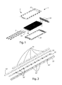
- a heating device 1 according to the present invention can be seen.
- Said heating device 1 comprises a support frame 2, one or more radiating elements or bars 3, installed on said support frame 2, and a plurality of dissipation fins 4 in thermal contact with said radiating bars 3, as will be better described in the following.
- Said support frame 2 comprises a first support 21 and a second support 22 coupled together, and an electrical connector 23, connectable to a plug of the car, in which said heating device 1 is installed.
- Said radiating bars 3, which in this embodiment are three, are arranged to generate heat, which is radiated from the dissipation fins 4, contained between said first support 21 and said second support 22 of the frame 2.
- Said radiating bars 3 also comprise a containment tube 31, hollow inside and made of a material capable of conducting heat and electric current, so that said containment tube 31 can also operate as electric terminal, and a longitudinal housing 32, arranged within said containment tube 31.
- Said longitudinal housing 32 is upwardly open and has a plurality of seats 32' obtained on the surface of said base 32", the function of which will be better clarified in the following.
- Said radiating bars comprise 3 inside a longitudinal electrode 33 having a terminal 33', which protrudes from said containment tube 31 when it is inserted into it.
- Said longitudinal electrode 33 is arranged so as not to come into contact with said containment tube 31, and it is connected with said connector 23.
- said radiating bars 3 comprise a plurality of PTC (Positive Temperature Coefficient) elements 34, which pads are made of ceramic, arranged in series to one another, and a plate 35, on which a plurality of compression means or springs 35' are obtained by carving, each made in the form of resilient tongues, said plate 35 being arranged between said longitudinal electrode 33 and the base of said longitudinal housing 32.
- PTC Physical Temperature Coefficient
- the radiating tubes 31, which, as said, also operate as electrical terminals, are connected to a power supply polarity of said car, while the terminals 33' of each electrode 33 of the longitudinal radiating bars 3, which, as said, is isolated from the containment tube 31 due to the longitudinal housing 32, in which it is placed, are connected to the other power supply polarity.
- PTC elements 34 each act as electrical resistance to the passage of the current, so as to generate heat that is transmitted to said containment tubes 31, which are also thermally conductive, and from the latter to said dissipation fins 4 which dissipate it.
- the electrical circuit is just closed with said PTC elements 34 in contact with the containment tube 31, which as said are connected to a power supply polarity of said car.
- the heat produced by said PTC elements 34 is dissipated by the dissipation fins 4 and is conveyed inside the passenger car possibly by means of a fan, so that the air flow passes through said dissipation fins 4, thus warming.
- a first assembly step (not shown in the figures) is to place and to fix the radiating tubes 31 through the fins 4.
- fins 4 are mutually stacked and have holes through which passes a containment tube 31.
- Each containment tube 31 is expanded mechanically, by means of an ogive or similar means, so as to adhere the dissipation fins 4 to the containment tube 31. In this way, a mechanical interference between the containment tube 31 and the dissipation fins 4, which ensures mechanical connection, is obtained.
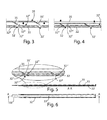
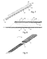
- each radiating element 3 the respective longitudinal terminal 33 and the respective plate 35 are moved or shifted in the direction indicated by arrow A.
- This causes the longitudinal translation of the plate 35 relative to the longitudinal housing 32, which then passes from a rest position (springs not compressed) to an operative position and then the simultaneous extraction of each spring 35' from the respective seat 32', which follows the path marked by the arrow C, with its consequent compression and the lifting, in the direction of arrow B, of the plate 35, the electrode 33 and, therefore, the PTC elements 34, thus guaranteeing a correct pressure between each PTC element 34 and the inner surface of said containment tube 31.
- Said seats 32' are identified by a lateral wall 32"', inclined with respect to said base 32" and intended to interfere with said tongues or springs 35', when the plate 35 moves from said rest position to said operative position, so as to facilitate said passage, by a lower wall 32 V and by a horizontal wall 32 IV , facing said lower wall 32 V , so that the tongue or spring 35' inserted in the respective 32' is at least partially inserted between said lower wall 32 V and said horizontal wall 32 IV , when said plate 35 is in said rest position.
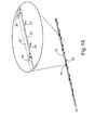
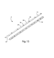
- Figures 13-15 show the structure, operation, and the assembly steps of a second embodiment of the heating device 1 according to the present invention.
- said radiating element 3 comprises separator elements 36, made of plastic material, which are co-molded together with said longitudinal electrode 33 and said plate 35 and spaced so as to allow the arrangement between each pair of them, of a PTC element 34.
- the assembly comolded between said longitudinal electrode 33, said plate 35 and said separator elements 36 is coupled with the longitudinal support 32 and then the PTC elements 34 are inserted, each one between a pair of separator elements 36, so as to remain spaced one from the other.
- An advantage of the present invention is, from one side, the fact that in the assembly steps, there are no elements or springs that are preloaded, thus avoiding any construction and execution problems, and on the other side, the fact that the parts that compose it are less complex.
Landscapes
- Engineering & Computer Science (AREA)
- Physics & Mathematics (AREA)
- Thermal Sciences (AREA)
- Chemical & Material Sciences (AREA)
- Combustion & Propulsion (AREA)
- Mechanical Engineering (AREA)
- General Engineering & Computer Science (AREA)
- Resistance Heating (AREA)
- Air-Conditioning For Vehicles (AREA)
- Automobile Manufacture Line, Endless Track Vehicle, Trailer (AREA)
- Lining Or Joining Of Plastics Or The Like (AREA)
Applications Claiming Priority (1)
| Application Number | Priority Date | Filing Date | Title |
|---|---|---|---|
| IT000440A ITRM20130440A1 (it) | 2013-07-26 | 2013-07-26 | Dispositivo di riscaldamento, in particolare per il riscaldamento dello abitacolo di una automobile, e metodo di montaggio di detto dispositivo. |
Publications (2)
| Publication Number | Publication Date |
|---|---|
| EP2840329A1 true EP2840329A1 (fr) | 2015-02-25 |
| EP2840329B1 EP2840329B1 (fr) | 2016-09-07 |
Family
ID=49263354
Family Applications (1)
| Application Number | Title | Priority Date | Filing Date |
|---|---|---|---|
| EP14425092.5A Active EP2840329B1 (fr) | 2013-07-26 | 2014-07-07 | Dispositif de chauffage et procédé de montage associé |
Country Status (2)
| Country | Link |
|---|---|
| EP (1) | EP2840329B1 (fr) |
| IT (1) | ITRM20130440A1 (fr) |
Cited By (5)
| Publication number | Priority date | Publication date | Assignee | Title |
|---|---|---|---|---|
| FR3073039A1 (fr) * | 2017-10-30 | 2019-05-03 | Valeo Systemes Thermiques | Plaque d'isolant electrique a reliefs de reception d'une electrode et de corps de chauffe pour module de chauffage de dispositif de chauffage pour vehicule automobile |
| CN109982879A (zh) * | 2016-12-13 | 2019-07-05 | 日本空调系统股份有限公司 | 车辆用空调装置的电加热器 |
| WO2022238538A1 (fr) * | 2021-05-14 | 2022-11-17 | Stego-Holding Gmbh | Dispositif de chauffage et procédé de fabrication d'un dispositif de chauffage |
| USD1040977S1 (en) | 2021-11-04 | 2024-09-03 | Stego-Holding Gmbh | Convector |
| RU2846381C2 (ru) * | 2021-05-14 | 2025-09-04 | Штего Холдинг Гмбх | Нагревательное устройство и способ изготовления нагревательного устройства |
Citations (5)
| Publication number | Priority date | Publication date | Assignee | Title |
|---|---|---|---|---|
| FR2793546A1 (fr) * | 1999-05-14 | 2000-11-17 | Valeo Climatisation | Echangeur de chaleur mixte eau/air et electrique |
| FR2826829A1 (fr) | 2001-06-27 | 2003-01-03 | Valeo Climatisation | Echangeur de chaleur a barreaux chauffants contenant des elements resistifs |
| WO2003088712A2 (fr) * | 2002-04-12 | 2003-10-23 | Behr Gmbh & Co. | Dispositif de transmission de chaleur utilise a des fins de chauffage et comprenant un systeme electrique chauffant |
| WO2007049746A1 (fr) * | 2005-10-28 | 2007-05-03 | Calsonic Kansei Corporation | Dispositif de chauffage |
| DE102007032896A1 (de) | 2006-08-22 | 2008-03-13 | Modine Korea Llc., Asan | Stabanordnung mit PTC-Vorrichtungen und diese enthaltender Vorwärmer |
-
2013
- 2013-07-26 IT IT000440A patent/ITRM20130440A1/it unknown
-
2014
- 2014-07-07 EP EP14425092.5A patent/EP2840329B1/fr active Active
Patent Citations (5)
| Publication number | Priority date | Publication date | Assignee | Title |
|---|---|---|---|---|
| FR2793546A1 (fr) * | 1999-05-14 | 2000-11-17 | Valeo Climatisation | Echangeur de chaleur mixte eau/air et electrique |
| FR2826829A1 (fr) | 2001-06-27 | 2003-01-03 | Valeo Climatisation | Echangeur de chaleur a barreaux chauffants contenant des elements resistifs |
| WO2003088712A2 (fr) * | 2002-04-12 | 2003-10-23 | Behr Gmbh & Co. | Dispositif de transmission de chaleur utilise a des fins de chauffage et comprenant un systeme electrique chauffant |
| WO2007049746A1 (fr) * | 2005-10-28 | 2007-05-03 | Calsonic Kansei Corporation | Dispositif de chauffage |
| DE102007032896A1 (de) | 2006-08-22 | 2008-03-13 | Modine Korea Llc., Asan | Stabanordnung mit PTC-Vorrichtungen und diese enthaltender Vorwärmer |
Cited By (6)
| Publication number | Priority date | Publication date | Assignee | Title |
|---|---|---|---|---|
| CN109982879A (zh) * | 2016-12-13 | 2019-07-05 | 日本空调系统股份有限公司 | 车辆用空调装置的电加热器 |
| FR3073039A1 (fr) * | 2017-10-30 | 2019-05-03 | Valeo Systemes Thermiques | Plaque d'isolant electrique a reliefs de reception d'une electrode et de corps de chauffe pour module de chauffage de dispositif de chauffage pour vehicule automobile |
| WO2019086802A1 (fr) * | 2017-10-30 | 2019-05-09 | Valeo Systemes Thermiques | Plaque d'isolant electrique a reliefs de reception d'une electrode et de corps de chauffe pour module de chauffage de dispositif de chauffage pour vehicule automobile |
| WO2022238538A1 (fr) * | 2021-05-14 | 2022-11-17 | Stego-Holding Gmbh | Dispositif de chauffage et procédé de fabrication d'un dispositif de chauffage |
| RU2846381C2 (ru) * | 2021-05-14 | 2025-09-04 | Штего Холдинг Гмбх | Нагревательное устройство и способ изготовления нагревательного устройства |
| USD1040977S1 (en) | 2021-11-04 | 2024-09-03 | Stego-Holding Gmbh | Convector |
Also Published As
| Publication number | Publication date |
|---|---|
| ITRM20130440A1 (it) | 2015-01-27 |
| EP2840329B1 (fr) | 2016-09-07 |
Similar Documents
| Publication | Publication Date | Title |
|---|---|---|
| EP3694293B1 (fr) | Chauffage ptc à commande indépendante et dispositif | |
| CN110324514B (zh) | 光学装置及其组装方法、加热其透镜的方法 | |
| CN100567843C (zh) | 电热装置 | |
| EP2840329B1 (fr) | Dispositif de chauffage et procédé de montage associé | |
| EP2730854B1 (fr) | Chauffage du compartiment intérieur de voiture | |
| KR101114583B1 (ko) | 피티씨 로드 조립체 | |
| CN105164862A (zh) | 用于电设备的控制模块 | |
| KR20100055262A (ko) | 고용량 피티씨 히터 | |
| KR102078194B1 (ko) | 차량용 히터 | |
| KR101597021B1 (ko) | 온도 제어 장치 | |
| UA120429C2 (uk) | Монолітна пластина з електричними контактами та спосіб її виготовлення | |
| US10363797B2 (en) | Vehicle heater | |
| CN106068571B (zh) | 在电池系统的两个电池模块之间的连接系统 | |
| JP6843980B2 (ja) | 電気補助加熱装置 | |
| KR101014494B1 (ko) | 피티씨 히터 | |
| EP2629585B1 (fr) | Appareillage de chauffage, en particulier pour chauffer le compartiment passager d'une automobile, et méthode relative à l'assemblage dudit appareillage | |
| KR101190101B1 (ko) | 자동차용 전열 히터 장치 | |
| CN108882399B (zh) | 制造ptc加热元件的方法 | |
| US9555690B2 (en) | Heating device composed of heating modules, and heating module for same | |
| KR20190010131A (ko) | Ptc 히터의 ptc 코어 구조 | |
| KR102002376B1 (ko) | Ptc 히터의 ptc 로드의 구조 | |
| CN106165205A (zh) | 电连接装置和电接触装置 | |
| KR20050018831A (ko) | Ртс 소자를 이용한 자동차용 히터 | |
| JP2015109274A (ja) | 電気ヒータ | |
| KR101992755B1 (ko) | 히터 및 이의 제조 방법 |
Legal Events
| Date | Code | Title | Description |
|---|---|---|---|
| PUAI | Public reference made under article 153(3) epc to a published international application that has entered the european phase |
Free format text: ORIGINAL CODE: 0009012 |
|
| 17P | Request for examination filed |
Effective date: 20140707 |
|
| AK | Designated contracting states |
Kind code of ref document: A1 Designated state(s): AL AT BE BG CH CY CZ DE DK EE ES FI FR GB GR HR HU IE IS IT LI LT LU LV MC MK MT NL NO PL PT RO RS SE SI SK SM TR |
|
| AX | Request for extension of the european patent |
Extension state: BA ME |
|
| R17P | Request for examination filed (corrected) |
Effective date: 20150817 |
|
| RBV | Designated contracting states (corrected) |
Designated state(s): AL AT BE BG CH CY CZ DE DK EE ES FI FR GB GR HR HU IE IS IT LI LT LU LV MC MK MT NL NO PL PT RO RS SE SI SK SM TR |
|
| GRAP | Despatch of communication of intention to grant a patent |
Free format text: ORIGINAL CODE: EPIDOSNIGR1 |
|
| INTG | Intention to grant announced |
Effective date: 20160428 |
|
| GRAS | Grant fee paid |
Free format text: ORIGINAL CODE: EPIDOSNIGR3 |
|
| GRAA | (expected) grant |
Free format text: ORIGINAL CODE: 0009210 |
|
| AK | Designated contracting states |
Kind code of ref document: B1 Designated state(s): AL AT BE BG CH CY CZ DE DK EE ES FI FR GB GR HR HU IE IS IT LI LT LU LV MC MK MT NL NO PL PT RO RS SE SI SK SM TR |
|
| REG | Reference to a national code |
Ref country code: GB Ref legal event code: FG4D |
|
| REG | Reference to a national code |
Ref country code: CH Ref legal event code: EP |
|
| REG | Reference to a national code |
Ref country code: IE Ref legal event code: FG4D |
|
| REG | Reference to a national code |
Ref country code: AT Ref legal event code: REF Ref document number: 827242 Country of ref document: AT Kind code of ref document: T Effective date: 20161015 |
|
| REG | Reference to a national code |
Ref country code: DE Ref legal event code: R096 Ref document number: 602014003525 Country of ref document: DE |
|
| REG | Reference to a national code |
Ref country code: LT Ref legal event code: MG4D |
|
| REG | Reference to a national code |
Ref country code: NL Ref legal event code: MP Effective date: 20160907 |
|
| PG25 | Lapsed in a contracting state [announced via postgrant information from national office to epo] |
Ref country code: NO Free format text: LAPSE BECAUSE OF FAILURE TO SUBMIT A TRANSLATION OF THE DESCRIPTION OR TO PAY THE FEE WITHIN THE PRESCRIBED TIME-LIMIT Effective date: 20161207 Ref country code: LT Free format text: LAPSE BECAUSE OF FAILURE TO SUBMIT A TRANSLATION OF THE DESCRIPTION OR TO PAY THE FEE WITHIN THE PRESCRIBED TIME-LIMIT Effective date: 20160907 Ref country code: FI Free format text: LAPSE BECAUSE OF FAILURE TO SUBMIT A TRANSLATION OF THE DESCRIPTION OR TO PAY THE FEE WITHIN THE PRESCRIBED TIME-LIMIT Effective date: 20160907 Ref country code: RS Free format text: LAPSE BECAUSE OF FAILURE TO SUBMIT A TRANSLATION OF THE DESCRIPTION OR TO PAY THE FEE WITHIN THE PRESCRIBED TIME-LIMIT Effective date: 20160907 Ref country code: HR Free format text: LAPSE BECAUSE OF FAILURE TO SUBMIT A TRANSLATION OF THE DESCRIPTION OR TO PAY THE FEE WITHIN THE PRESCRIBED TIME-LIMIT Effective date: 20160907 |
|
| REG | Reference to a national code |
Ref country code: AT Ref legal event code: MK05 Ref document number: 827242 Country of ref document: AT Kind code of ref document: T Effective date: 20160907 |
|
| PG25 | Lapsed in a contracting state [announced via postgrant information from national office to epo] |
Ref country code: GR Free format text: LAPSE BECAUSE OF FAILURE TO SUBMIT A TRANSLATION OF THE DESCRIPTION OR TO PAY THE FEE WITHIN THE PRESCRIBED TIME-LIMIT Effective date: 20161208 Ref country code: ES Free format text: LAPSE BECAUSE OF FAILURE TO SUBMIT A TRANSLATION OF THE DESCRIPTION OR TO PAY THE FEE WITHIN THE PRESCRIBED TIME-LIMIT Effective date: 20160907 Ref country code: LV Free format text: LAPSE BECAUSE OF FAILURE TO SUBMIT A TRANSLATION OF THE DESCRIPTION OR TO PAY THE FEE WITHIN THE PRESCRIBED TIME-LIMIT Effective date: 20160907 Ref country code: NL Free format text: LAPSE BECAUSE OF FAILURE TO SUBMIT A TRANSLATION OF THE DESCRIPTION OR TO PAY THE FEE WITHIN THE PRESCRIBED TIME-LIMIT Effective date: 20160907 Ref country code: SE Free format text: LAPSE BECAUSE OF FAILURE TO SUBMIT A TRANSLATION OF THE DESCRIPTION OR TO PAY THE FEE WITHIN THE PRESCRIBED TIME-LIMIT Effective date: 20160907 |
|
| PG25 | Lapsed in a contracting state [announced via postgrant information from national office to epo] |
Ref country code: RO Free format text: LAPSE BECAUSE OF FAILURE TO SUBMIT A TRANSLATION OF THE DESCRIPTION OR TO PAY THE FEE WITHIN THE PRESCRIBED TIME-LIMIT Effective date: 20160907 Ref country code: EE Free format text: LAPSE BECAUSE OF FAILURE TO SUBMIT A TRANSLATION OF THE DESCRIPTION OR TO PAY THE FEE WITHIN THE PRESCRIBED TIME-LIMIT Effective date: 20160907 |
|
| PG25 | Lapsed in a contracting state [announced via postgrant information from national office to epo] |
Ref country code: SM Free format text: LAPSE BECAUSE OF FAILURE TO SUBMIT A TRANSLATION OF THE DESCRIPTION OR TO PAY THE FEE WITHIN THE PRESCRIBED TIME-LIMIT Effective date: 20160907 Ref country code: PT Free format text: LAPSE BECAUSE OF FAILURE TO SUBMIT A TRANSLATION OF THE DESCRIPTION OR TO PAY THE FEE WITHIN THE PRESCRIBED TIME-LIMIT Effective date: 20170109 Ref country code: CZ Free format text: LAPSE BECAUSE OF FAILURE TO SUBMIT A TRANSLATION OF THE DESCRIPTION OR TO PAY THE FEE WITHIN THE PRESCRIBED TIME-LIMIT Effective date: 20160907 Ref country code: BG Free format text: LAPSE BECAUSE OF FAILURE TO SUBMIT A TRANSLATION OF THE DESCRIPTION OR TO PAY THE FEE WITHIN THE PRESCRIBED TIME-LIMIT Effective date: 20161207 Ref country code: AT Free format text: LAPSE BECAUSE OF FAILURE TO SUBMIT A TRANSLATION OF THE DESCRIPTION OR TO PAY THE FEE WITHIN THE PRESCRIBED TIME-LIMIT Effective date: 20160907 Ref country code: IS Free format text: LAPSE BECAUSE OF FAILURE TO SUBMIT A TRANSLATION OF THE DESCRIPTION OR TO PAY THE FEE WITHIN THE PRESCRIBED TIME-LIMIT Effective date: 20170107 Ref country code: SK Free format text: LAPSE BECAUSE OF FAILURE TO SUBMIT A TRANSLATION OF THE DESCRIPTION OR TO PAY THE FEE WITHIN THE PRESCRIBED TIME-LIMIT Effective date: 20160907 Ref country code: BE Free format text: LAPSE BECAUSE OF FAILURE TO SUBMIT A TRANSLATION OF THE DESCRIPTION OR TO PAY THE FEE WITHIN THE PRESCRIBED TIME-LIMIT Effective date: 20160907 Ref country code: PL Free format text: LAPSE BECAUSE OF FAILURE TO SUBMIT A TRANSLATION OF THE DESCRIPTION OR TO PAY THE FEE WITHIN THE PRESCRIBED TIME-LIMIT Effective date: 20160907 |
|
| REG | Reference to a national code |
Ref country code: DE Ref legal event code: R097 Ref document number: 602014003525 Country of ref document: DE |
|
| REG | Reference to a national code |
Ref country code: FR Ref legal event code: PLFP Year of fee payment: 4 |
|
| PLBE | No opposition filed within time limit |
Free format text: ORIGINAL CODE: 0009261 |
|
| STAA | Information on the status of an ep patent application or granted ep patent |
Free format text: STATUS: NO OPPOSITION FILED WITHIN TIME LIMIT |
|
| PG25 | Lapsed in a contracting state [announced via postgrant information from national office to epo] |
Ref country code: DK Free format text: LAPSE BECAUSE OF FAILURE TO SUBMIT A TRANSLATION OF THE DESCRIPTION OR TO PAY THE FEE WITHIN THE PRESCRIBED TIME-LIMIT Effective date: 20160907 |
|
| 26N | No opposition filed |
Effective date: 20170608 |
|
| PG25 | Lapsed in a contracting state [announced via postgrant information from national office to epo] |
Ref country code: SI Free format text: LAPSE BECAUSE OF FAILURE TO SUBMIT A TRANSLATION OF THE DESCRIPTION OR TO PAY THE FEE WITHIN THE PRESCRIBED TIME-LIMIT Effective date: 20160907 |
|
| REG | Reference to a national code |
Ref country code: CH Ref legal event code: PL |
|
| REG | Reference to a national code |
Ref country code: IE Ref legal event code: MM4A |
|
| PG25 | Lapsed in a contracting state [announced via postgrant information from national office to epo] |
Ref country code: LI Free format text: LAPSE BECAUSE OF NON-PAYMENT OF DUE FEES Effective date: 20170731 Ref country code: IE Free format text: LAPSE BECAUSE OF NON-PAYMENT OF DUE FEES Effective date: 20170707 Ref country code: CH Free format text: LAPSE BECAUSE OF NON-PAYMENT OF DUE FEES Effective date: 20170731 |
|
| REG | Reference to a national code |
Ref country code: FR Ref legal event code: PLFP Year of fee payment: 5 |
|
| PG25 | Lapsed in a contracting state [announced via postgrant information from national office to epo] |
Ref country code: LU Free format text: LAPSE BECAUSE OF NON-PAYMENT OF DUE FEES Effective date: 20170707 |
|
| PG25 | Lapsed in a contracting state [announced via postgrant information from national office to epo] |
Ref country code: MT Free format text: LAPSE BECAUSE OF NON-PAYMENT OF DUE FEES Effective date: 20170707 |
|
| PG25 | Lapsed in a contracting state [announced via postgrant information from national office to epo] |
Ref country code: AL Free format text: LAPSE BECAUSE OF FAILURE TO SUBMIT A TRANSLATION OF THE DESCRIPTION OR TO PAY THE FEE WITHIN THE PRESCRIBED TIME-LIMIT Effective date: 20160907 |
|
| GBPC | Gb: european patent ceased through non-payment of renewal fee |
Effective date: 20180707 |
|
| PG25 | Lapsed in a contracting state [announced via postgrant information from national office to epo] |
Ref country code: GB Free format text: LAPSE BECAUSE OF NON-PAYMENT OF DUE FEES Effective date: 20180707 |
|
| PG25 | Lapsed in a contracting state [announced via postgrant information from national office to epo] |
Ref country code: HU Free format text: LAPSE BECAUSE OF FAILURE TO SUBMIT A TRANSLATION OF THE DESCRIPTION OR TO PAY THE FEE WITHIN THE PRESCRIBED TIME-LIMIT; INVALID AB INITIO Effective date: 20140707 Ref country code: MC Free format text: LAPSE BECAUSE OF FAILURE TO SUBMIT A TRANSLATION OF THE DESCRIPTION OR TO PAY THE FEE WITHIN THE PRESCRIBED TIME-LIMIT Effective date: 20160907 |
|
| PGFP | Annual fee paid to national office [announced via postgrant information from national office to epo] |
Ref country code: FR Payment date: 20190619 Year of fee payment: 6 |
|
| PG25 | Lapsed in a contracting state [announced via postgrant information from national office to epo] |
Ref country code: CY Free format text: LAPSE BECAUSE OF FAILURE TO SUBMIT A TRANSLATION OF THE DESCRIPTION OR TO PAY THE FEE WITHIN THE PRESCRIBED TIME-LIMIT Effective date: 20160907 |
|
| PGFP | Annual fee paid to national office [announced via postgrant information from national office to epo] |
Ref country code: DE Payment date: 20190730 Year of fee payment: 6 |
|
| PG25 | Lapsed in a contracting state [announced via postgrant information from national office to epo] |
Ref country code: MK Free format text: LAPSE BECAUSE OF FAILURE TO SUBMIT A TRANSLATION OF THE DESCRIPTION OR TO PAY THE FEE WITHIN THE PRESCRIBED TIME-LIMIT Effective date: 20160907 |
|
| PG25 | Lapsed in a contracting state [announced via postgrant information from national office to epo] |
Ref country code: TR Free format text: LAPSE BECAUSE OF FAILURE TO SUBMIT A TRANSLATION OF THE DESCRIPTION OR TO PAY THE FEE WITHIN THE PRESCRIBED TIME-LIMIT Effective date: 20160907 |
|
| REG | Reference to a national code |
Ref country code: DE Ref legal event code: R119 Ref document number: 602014003525 Country of ref document: DE |
|
| PG25 | Lapsed in a contracting state [announced via postgrant information from national office to epo] |
Ref country code: FR Free format text: LAPSE BECAUSE OF NON-PAYMENT OF DUE FEES Effective date: 20200731 |
|
| PG25 | Lapsed in a contracting state [announced via postgrant information from national office to epo] |
Ref country code: DE Free format text: LAPSE BECAUSE OF NON-PAYMENT OF DUE FEES Effective date: 20210202 |
|
| PGFP | Annual fee paid to national office [announced via postgrant information from national office to epo] |
Ref country code: IT Payment date: 20250529 Year of fee payment: 12 |