EP2840345A2 - Ailette d'échangeur de chaleur avec élément anti-fissurage - Google Patents
Ailette d'échangeur de chaleur avec élément anti-fissurage Download PDFInfo
- Publication number
- EP2840345A2 EP2840345A2 EP14181032.5A EP14181032A EP2840345A2 EP 2840345 A2 EP2840345 A2 EP 2840345A2 EP 14181032 A EP14181032 A EP 14181032A EP 2840345 A2 EP2840345 A2 EP 2840345A2
- Authority
- EP
- European Patent Office
- Prior art keywords
- fins
- heat exchanger
- slots
- fin
- air
- Prior art date
- Legal status (The legal status is an assumption and is not a legal conclusion. Google has not performed a legal analysis and makes no representation as to the accuracy of the status listed.)
- Granted
Links
Images


Classifications
-
- B—PERFORMING OPERATIONS; TRANSPORTING
- B23—MACHINE TOOLS; METAL-WORKING NOT OTHERWISE PROVIDED FOR
- B23P—METAL-WORKING NOT OTHERWISE PROVIDED FOR; COMBINED OPERATIONS; UNIVERSAL MACHINE TOOLS
- B23P15/00—Making specific metal objects by operations not covered by a single other subclass or a group in this subclass
- B23P15/26—Making specific metal objects by operations not covered by a single other subclass or a group in this subclass heat exchangers or the like
-
- B—PERFORMING OPERATIONS; TRANSPORTING
- B23—MACHINE TOOLS; METAL-WORKING NOT OTHERWISE PROVIDED FOR
- B23H—WORKING OF METAL BY THE ACTION OF A HIGH CONCENTRATION OF ELECTRIC CURRENT ON A WORKPIECE USING AN ELECTRODE WHICH TAKES THE PLACE OF A TOOL; SUCH WORKING COMBINED WITH OTHER FORMS OF WORKING OF METAL
- B23H1/00—Electrical discharge machining, i.e. removing metal with a series of rapidly recurring electrical discharges between an electrode and a workpiece in the presence of a fluid dielectric
-
- F—MECHANICAL ENGINEERING; LIGHTING; HEATING; WEAPONS; BLASTING
- F28—HEAT EXCHANGE IN GENERAL
- F28D—HEAT-EXCHANGE APPARATUS, NOT PROVIDED FOR IN ANOTHER SUBCLASS, IN WHICH THE HEAT-EXCHANGE MEDIA DO NOT COME INTO DIRECT CONTACT
- F28D9/00—Heat-exchange apparatus having stationary plate-like or laminated conduit assemblies for both heat-exchange media, the media being in contact with different sides of a conduit wall
- F28D9/0062—Heat-exchange apparatus having stationary plate-like or laminated conduit assemblies for both heat-exchange media, the media being in contact with different sides of a conduit wall the conduits for one heat-exchange medium being formed by spaced plates with inserted elements
-
- F—MECHANICAL ENGINEERING; LIGHTING; HEATING; WEAPONS; BLASTING
- F28—HEAT EXCHANGE IN GENERAL
- F28F—DETAILS OF HEAT-EXCHANGE AND HEAT-TRANSFER APPARATUS, OF GENERAL APPLICATION
- F28F3/00—Plate-like or laminated elements; Assemblies of plate-like or laminated elements
- F28F3/02—Elements or assemblies thereof with means for increasing heat-transfer area, e.g. with fins, with recesses, with corrugations
- F28F3/025—Elements or assemblies thereof with means for increasing heat-transfer area, e.g. with fins, with recesses, with corrugations the means being corrugated, plate-like elements
-
- F—MECHANICAL ENGINEERING; LIGHTING; HEATING; WEAPONS; BLASTING
- F28—HEAT EXCHANGE IN GENERAL
- F28F—DETAILS OF HEAT-EXCHANGE AND HEAT-TRANSFER APPARATUS, OF GENERAL APPLICATION
- F28F2225/00—Reinforcing means
- F28F2225/06—Reinforcing means for fins
-
- F—MECHANICAL ENGINEERING; LIGHTING; HEATING; WEAPONS; BLASTING
- F28—HEAT EXCHANGE IN GENERAL
- F28F—DETAILS OF HEAT-EXCHANGE AND HEAT-TRANSFER APPARATUS, OF GENERAL APPLICATION
- F28F2265/00—Safety or protection arrangements; Arrangements for preventing malfunction
- F28F2265/26—Safety or protection arrangements; Arrangements for preventing malfunction for allowing differential expansion between elements
-
- Y—GENERAL TAGGING OF NEW TECHNOLOGICAL DEVELOPMENTS; GENERAL TAGGING OF CROSS-SECTIONAL TECHNOLOGIES SPANNING OVER SEVERAL SECTIONS OF THE IPC; TECHNICAL SUBJECTS COVERED BY FORMER USPC CROSS-REFERENCE ART COLLECTIONS [XRACs] AND DIGESTS
- Y10—TECHNICAL SUBJECTS COVERED BY FORMER USPC
- Y10T—TECHNICAL SUBJECTS COVERED BY FORMER US CLASSIFICATION
- Y10T29/00—Metal working
- Y10T29/49—Method of mechanical manufacture
- Y10T29/4935—Heat exchanger or boiler making
Definitions
- This invention relates generally to an air generation unit (AGU) suitable for an aircraft.
- the invention relates to the operating lifetime of a heat exchanger in an AGU.
- AGUs typically include at least one air cycle machine (ACM) and at least one heat exchanger that receives air from a pressurized air source, such as bleed air from an engine, to provide cooled air to the aircraft cabin and cockpit.
- ACM air cycle machine
- heat exchanger that receives air from a pressurized air source, such as bleed air from an engine, to provide cooled air to the aircraft cabin and cockpit.
- An AGU may include a heat exchanger having primary and secondary heat exchangers. Bleed air is taken from an intermediate or high pressure stage of the turbine engine. The bleed air is precooled within the primary heat exchanger with the heat being rejected to ram air and then communicated to the compressor of the ACM. After compression, the air is communicated through a secondary heat exchanger to a condenser. Condenser water vapor is extracted by a water collector, and the dehumidified air is sent to a turbine where the air is expanded to generate cold air.
- the AGU may include first and second turbines. The second turbine receives cold air from the first turbine and further expands the cold air to produce subfreezing air sufficient to cool larger aircraft. The cold air is sent to an environmental control system (ECS) that further conditions and distributes the air to the aircraft.
- ECS environmental control system
- the primary heat exchanger is a component of an AGU that is susceptible to damage as a result of exposure to thermal cycling. Improvements of the primary heat exchanger will result in extended periods of service.
- a method of extending the lifetime of brazed fin structures may include inserting crack arrestors, such as slots, in the fins.
- the fin structures may be brazed primary hot inlet wavy fin structures.
- the slots increase the mechanical compliance of the fins as well as act as crack arrestors should a thermally induced fracture occur.
- a brazed heat exchanger structure with an inlet and outlet for cooling a hot gas stream consists of a metal core containing metal fins to conduct heat away from the hot gas.
- the fins may be closely spaced wavy metal fins.
- the fin or fins near (or nearest) the hot gas inlet are shaped to increase the mechanical compliance of the structure and to eliminate thermally induced crack initiation and propagation in the fins.
- Air generation units (AGU) of the present invention include a pressurized air source, such as a turbine engine that provides bleed air, air cycle machines (ACM) connected to the pressurized air source, primary and secondary heat exchangers that cool the air from the air source, and a system for distributing the conditioned air for the aircraft.
- the ACMs contain a compressor receiving the air from a primary heat exchanger to provide compressed air that is sent to a secondary heat exchanger to be cooled.
- the compressed air is passed through a condenser and a water collector to remove moisture from the air before being sent to a first turbine.
- the first turbine expands the dehumidified air to produce a first conditioned air having a first temperature.
- a second turbine further expands the conditioned air to produce even cooler air that is then distributed throughout the cabin and cockpit of an aircraft. This system is described in commonly owned patent US7,188,488 to Army, Jr. et al.
- FIG. 1 A schematic of an air generation unit (AGU) showing dual primary heat exchangers 36 of a preferred embodiment of the present invention is shown in FIG. 1 .
- AGU 10 includes first 16 and second 18 air cycle machines (ACM).
- ACMs 16 and 18 are in four wheel configuration including a fan 20, compressor 22, and first 24 and second 26 turbines.
- Shafts 82 support fans 20, compressors 22 and first and second turbines 24 and 26.
- Fans 20 are arranged within the ram air flow.
- Fans 20 pull air through heat exchangers 36 and 38 if the aircraft is not moving.
- FIG. 1 is an example only and the present invention can be applied to heat exchanger structures in general.
- ram air enters heat exchangers through header 30 along ram air flow path R wherein the heat exchangers includes dual primary 36 and dual secondary 38 heat exchangers.
- Primary heat exchangers 36 are air-to-air heat exchangers that cool bleed air from bleed air inlets 14 from an engine prior to being compressed by compressors 22.
- Secondary heat exchangers 38 cool the compressed air from compressors 22 prior to being sent to turbines 24 for expansion and further cooling.
- Condensers 44 in the system collect water vapor and dehumidify air from secondary heat exchangers 38.
- pressurized air from the engine enters from bleed air inlets 14.
- the high temperature bleed air passes through primary heat exchangers 36 to cool the air to a temperature that is suitable for use with aluminum components.
- the cooled air from primary heat exchangers 36 enters compressor inlets 62 where it is compressed by compressors 22 to provide compressed air.
- the temperature of the compressed air has been raised by compressors 22 such that it must be passed through secondary heat exchangers 38.
- the compressed air exits compressors 22 through compressor outlets 64 and passes into secondary heat exchangers 38.
- the cooled air from secondary heat exchangers 38 is communicated to condenser 44 to form water vapor of sufficient character to be collected by water collector 46.
- the dehumidified air exits water collector outlet 68 and enters inlets 69 of first turbines 24.
- the dehumidified air is expanded by first turbines 24 to produce a first conditioned air having a first temperature that may be as low as approximately 1°C (34° F).
- the conditioned air from first turbine outlets 70 is communicated through a manifold and sent to condenser 44 through condenser cold inlet 72.
- Condenser 44 and water collector 46 remove additional moisture from the conditioned air from first turbines 24.
- the further dehumidified air is communicated through a manifold through condenser cold outlet 74 into second turbine inlets 76 where the air is further expanded by second turbines 26.
- the conditioned air temperature produced by second turbines 26 is lower than the conditioned air temperature produced by first turbines 24.
- the conditioned air produced by second turbines 26 may be of sub-freezing temperatures which better enables AGU 10 to cool a large aircraft.
- Air from second turbine outlets 78 is sent to a distribution system in environmental control unit (ECU) 84 for cooling of the aircraft.
- ECU environmental control unit
- Primary heat exchanger 100 is an air-to-air heat exchanger that cools hot bleed air from an engine prior to being compressed by a compressor.
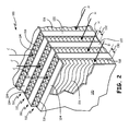
- Primary heat exchanger 100 comprises stacked primary cold fin structures 110 and stacked primary hot bleed fin structures 112.
- Primary cold fin structure 110 contains metal foil heat exchanger elements 114 in an accordion pattern that act to remove heat from adjacent hot fin structures 112 by thermal conduction.
- Primary hot fin structures 112 contain stacked layers of metal foil fin elements 116 in a wavy pattern to maximize contact between the wavy fins and hot bleed air passing through the primary hot fin structure.
- Cold ram air from header 30 enters stacked primary cold fin structures 110 in the direction of arrows C and cools cold heat exchanger elements 114 in cold fin structures 110.
- Hot bleed air from an engine bleed system enters stacked primary hot fin structures 112, in the direction of arrows H and is cooled from ram air flow in stacked cold fin structures 110.
- Hot and cold air flow in heat exchanger 100 are perpendicular to each other as indicated in FIG. 2 .
- Stacked cold fin structures 110 contain metal foil heat exchanger elements 114 in an accordion pattern that act to remove heat from adjacent hot fin structures 112 by conduction.
- Stacked primary hot fin structures 112 contain stacked layers of metal foil fin elements 116 in a wavy pattern to maximize contact between the wavy fins and hot air passing through the primary hot fin structure.
- the stacked primary hot fin structures 112 and cold fin structures 110 are separated by parting sheets 118. Parting sheets 118 are also formed from metal alloys and act to support the hot and cold heat exchanger foil elements 114 and 116 in the hot and cold fin structures.
- End sheets 120 form the outside barriers of primary hot heat exchanger 100.
- Closure bars 122 and 124 form the outside barriers of cold fin structures 110 and hot fin structures 112, respectively.
- Additional structural elements are core bands which act to support the overall stack of hot and cold fin structures of heat exchanger 100.
- the metal components of heat exchanger 100 may be any metal known in the art of heat exchanger design.
- the metal components of an aircraft heat exchanger may be aluminum.
- heat exchanger 100 All internal elements of heat exchanger 100 are joined by brazing with the exception of the core bands and other mounting fixtures and mounting assemblies. During final assembly, the core bands and other mounting fixtures are typically welded to the brazed heat exchanger structure to provide support.
- Finite element analysis has shown that a more compliant fin geometry can reduce the tensile stress in a bleed fin by up to six fold thereby increasing the time for crack initiation and the resulting lifetime of the structure.
- FIGS. 3A-C show views of a hot bleed fin structure with wavy fin elements that are slotted to increase the fin compliance.
- FIG. 3A shows a side view of a wavy bleed fin structure in the vicinity of the hot bleed entrance. Arrows H indicate the bleed air direction.
- FIG. 3A shows a side view of the wavy fin structure of FIG. 2 viewed perpendicular to end face 120.
- FIGS. 3B and 3C are top views of the bleed fin structure of FIG. 3A showing two embodiments of the invention. In FIG. 3B , the fins are slotted on one side only. In FIG.
- the slots 130 are on alternate sides of the fin. As indicated by arrow d, slots 130 are inserted in the fins to a finite depth into the fin structure. The slot depth is from about 50 percent to about 100 percent of the fin width. The slot width is from about two times to about eight times the fin thickness. The slots 130 are preferably inserted into the fins by electrical discharge machining (EDM).
- EDM electrical discharge machining
- a method of extending the lifetime of brazed fin structures of heat exchanger cores may include: providing fins with a mechanical compliance; increasing the mechanical compliance of fins, for example hot and cold fins, near the hot gas entry region.
- the method of the preceding paragraph can optionally include, additionally and/or alternatively any, one or more of the following features, configurations and/or additional components:
- a slot width may be from about 2 times to about 8 times the fin thickness.
- a brazed heat exchanger structure with an inlet and outlet for cooling a hot gas may include: an external metal duct containing closely spaced metal fins for conducting heat away from the hot gas;
- the metal fins near the inlet may be shaped to increase the mechanical compliance of the structure thereby reducing thermally induced fractures in the fins during operation.
- the structure of the preceding paragraph can optionally include, additionally, and/or alternatively any, one or more of the following features, configurations and/or additional components:
- a brazed heat exchanger structure with improved lifetime may include: stacked alternating cold fin and hot fin structures separated by parting sheets; closure bars on the ends of the hot and cold fin structures; and slotted fins in the hot fin structure near the hot air entrance that increase the fracture resistance of the fins by increasing the mechanical compliance of the structure and acting as crack arrestors.
- the heat exchanger structure of the preceding paragraph can optionally include, additionally and/or alternatively any, one or more of the following features, configurations and/or additional components:
Landscapes
- Engineering & Computer Science (AREA)
- Mechanical Engineering (AREA)
- Physics & Mathematics (AREA)
- Thermal Sciences (AREA)
- General Engineering & Computer Science (AREA)
- Heat-Exchange Devices With Radiators And Conduit Assemblies (AREA)
- Cooling Or The Like Of Electrical Apparatus (AREA)
Applications Claiming Priority (1)
| Application Number | Priority Date | Filing Date | Title |
|---|---|---|---|
| US13/972,315 US10112270B2 (en) | 2013-08-21 | 2013-08-21 | Heat exchanger fin with crack arrestor |
Publications (3)
| Publication Number | Publication Date |
|---|---|
| EP2840345A2 true EP2840345A2 (fr) | 2015-02-25 |
| EP2840345A3 EP2840345A3 (fr) | 2015-04-29 |
| EP2840345B1 EP2840345B1 (fr) | 2018-02-07 |
Family
ID=51357778
Family Applications (1)
| Application Number | Title | Priority Date | Filing Date |
|---|---|---|---|
| EP14181032.5A Active EP2840345B1 (fr) | 2013-08-21 | 2014-08-14 | Echangeur brazé avec ailettes d'échangeur de chaleur comprenant des éléments anti-fissurage |
Country Status (2)
| Country | Link |
|---|---|
| US (1) | US10112270B2 (fr) |
| EP (1) | EP2840345B1 (fr) |
Cited By (3)
| Publication number | Priority date | Publication date | Assignee | Title |
|---|---|---|---|---|
| EP3106817A1 (fr) * | 2015-06-18 | 2016-12-21 | Hamilton Sundstrand Corporation | Échangeur thermique à ailettes-plaques |
| FR3130359A1 (fr) | 2021-12-13 | 2023-06-16 | Liebherr-Aerospace Toulouse Sas | Dispositif d’échange thermique comprenant au moins un dispositif limiteur de débit, système de conditionnement d’air et véhicule |
| EP3589908B1 (fr) * | 2017-02-28 | 2025-06-18 | General Electric Company | Échangeur de chaleur fabriqué de manière additive |
Families Citing this family (7)
| Publication number | Priority date | Publication date | Assignee | Title |
|---|---|---|---|---|
| WO2016007156A1 (fr) * | 2014-07-09 | 2016-01-14 | Halliburton Energy Services, Inc. | Indicateur de fissure de perforation |
| US9598175B2 (en) * | 2015-04-24 | 2017-03-21 | Hamilton Sundstrand Corporation | Modular environmental air conditioning system |
| US20180244127A1 (en) * | 2017-02-28 | 2018-08-30 | General Electric Company | Thermal management system and method |
| US11306979B2 (en) * | 2018-12-05 | 2022-04-19 | Hamilton Sundstrand Corporation | Heat exchanger riblet and turbulator features for improved manufacturability and performance |
| US11060458B2 (en) * | 2019-04-02 | 2021-07-13 | Hamilton Sundstrand Corporation | Heat exchanger thermal shock reducer |
| US12215933B2 (en) | 2020-11-30 | 2025-02-04 | Dana Canada Corporation | Compact heat exchanger with wavy fin turbulizer |
| US12259194B2 (en) | 2023-07-10 | 2025-03-25 | General Electric Company | Thermal management system |
Citations (1)
| Publication number | Priority date | Publication date | Assignee | Title |
|---|---|---|---|---|
| US7188488B2 (en) | 2003-03-12 | 2007-03-13 | Hamilton Sundstrand | Pack and a half condensing cycle pack with combined heat exchangers |
Family Cites Families (24)
| Publication number | Priority date | Publication date | Assignee | Title |
|---|---|---|---|---|
| US2571631A (en) * | 1947-02-26 | 1951-10-16 | Kellogg M W Co | Heat exchange element |
| US2656158A (en) * | 1948-07-23 | 1953-10-20 | Air Preheater | Plate type heat exchanger and method of manufacturing same |
| US2634958A (en) * | 1948-12-03 | 1953-04-14 | Modine Mfg Co | Heat exchanger |
| US3517731A (en) | 1967-09-25 | 1970-06-30 | United Aircraft Corp | Self-sealing fluid/fluid heat exchanger |
| US3601185A (en) * | 1969-11-04 | 1971-08-24 | United Aircraft Corp | Heat exchanger construction |
| US4107919A (en) * | 1975-03-19 | 1978-08-22 | The United States Of America As Represented By The Administrator Of The National Aeronautics And Space Administration | Heat exchanger |
| JPS5639908Y2 (fr) | 1977-04-23 | 1981-09-17 | ||
| US4442886A (en) * | 1982-04-19 | 1984-04-17 | North Atlantic Technologies, Inc. | Floating plate heat exchanger |
| DE3521914A1 (de) * | 1984-06-20 | 1986-01-02 | Showa Aluminum Corp., Sakai, Osaka | Waermetauscher in fluegelplattenbauweise |
| US4838041A (en) * | 1987-02-05 | 1989-06-13 | Gte Laboratories Incorporated | Expansion/evaporation cooling system for microelectronic devices |
| JP2786702B2 (ja) * | 1989-12-07 | 1998-08-13 | 昭和アルミニウム株式会社 | 複式一体型熱交換器 |
| US5260024A (en) * | 1990-12-18 | 1993-11-09 | Westinghouse Electric Corp. | Test specimen for evaluating crack propagation due to corrosion |
| DE69507070T2 (de) * | 1994-04-12 | 1999-06-10 | Showa Aluminum Corp., Sakai, Osaka | Doppelwärmetauscher in Stapelbauweise |
| AU729629B2 (en) * | 1996-08-12 | 2001-02-08 | Calsonic Corporation | Integral-type heat exchanger |
| JP4019113B2 (ja) * | 1997-11-13 | 2007-12-12 | 株式会社ティラド | 一体型熱交換器のフィンとその製造方法 |
| JPH11153389A (ja) | 1997-11-21 | 1999-06-08 | Showa Alum Corp | 熱交換器の製造方法 |
| US20020139515A1 (en) * | 1999-07-02 | 2002-10-03 | Kaveh Azar | Heat sink with textured regions |
| US7000425B2 (en) | 2003-03-12 | 2006-02-21 | Hamilton Sundstrand | Manifold for pack and a half condensing cycle pack with combined heat exchangers |
| US20060157234A1 (en) * | 2005-01-14 | 2006-07-20 | Honeywell International Inc. | Microchannel heat exchanger fabricated by wire electro-discharge machining |
| JP4683987B2 (ja) * | 2005-04-14 | 2011-05-18 | カルソニックカンセイ株式会社 | 一体型熱交換器のフィン構造 |
| US8276654B2 (en) * | 2005-11-17 | 2012-10-02 | Hamilton Sundstrand Corporation | Core assembly with deformation preventing features |
| US8327924B2 (en) * | 2008-07-03 | 2012-12-11 | Honeywell International Inc. | Heat exchanger fin containing notches |
| US20120193083A1 (en) | 2011-02-02 | 2012-08-02 | Hamilton Sundstrand Space Systems International, Inc. | Heat exchanger assembly with fin locating structure |
| US20150047820A1 (en) * | 2013-08-14 | 2015-02-19 | Hamilton Sundstrand Corporation | Bendable heat exchanger |
-
2013
- 2013-08-21 US US13/972,315 patent/US10112270B2/en active Active
-
2014
- 2014-08-14 EP EP14181032.5A patent/EP2840345B1/fr active Active
Patent Citations (1)
| Publication number | Priority date | Publication date | Assignee | Title |
|---|---|---|---|---|
| US7188488B2 (en) | 2003-03-12 | 2007-03-13 | Hamilton Sundstrand | Pack and a half condensing cycle pack with combined heat exchangers |
Cited By (5)
| Publication number | Priority date | Publication date | Assignee | Title |
|---|---|---|---|---|
| EP3106817A1 (fr) * | 2015-06-18 | 2016-12-21 | Hamilton Sundstrand Corporation | Échangeur thermique à ailettes-plaques |
| US10954858B2 (en) | 2015-06-18 | 2021-03-23 | Hamilton Sunstrand Corporation | Plate fin heat exchanger |
| EP3589908B1 (fr) * | 2017-02-28 | 2025-06-18 | General Electric Company | Échangeur de chaleur fabriqué de manière additive |
| FR3130359A1 (fr) | 2021-12-13 | 2023-06-16 | Liebherr-Aerospace Toulouse Sas | Dispositif d’échange thermique comprenant au moins un dispositif limiteur de débit, système de conditionnement d’air et véhicule |
| WO2023110685A1 (fr) | 2021-12-13 | 2023-06-22 | Liebherr-Aerospace Toulouse Sas | Dispositif d echange thermique comprenant des dispositifs limiteurs de debit, systeme de conditionnement d air et vehicule |
Also Published As
| Publication number | Publication date |
|---|---|
| US10112270B2 (en) | 2018-10-30 |
| US20150053380A1 (en) | 2015-02-26 |
| EP2840345A3 (fr) | 2015-04-29 |
| EP2840345B1 (fr) | 2018-02-07 |
Similar Documents
| Publication | Publication Date | Title |
|---|---|---|
| EP2840345B1 (fr) | Echangeur brazé avec ailettes d'échangeur de chaleur comprenant des éléments anti-fissurage | |
| US10954858B2 (en) | Plate fin heat exchanger | |
| US9051943B2 (en) | Gas turbine engine heat exchanger fins with periodic gaps | |
| US20170108291A1 (en) | Plate-like air-cooled engine surface cooler with fluid channel and varying fin geometry | |
| US11248526B2 (en) | Fan casing assembly and method | |
| US20080110603A1 (en) | Integrated heat exchangers for ecs and obiggs applications | |
| US9238284B2 (en) | Methods for forming a heat exchanger and portions thereof | |
| EP2853851B1 (fr) | Réduction de la contrainte de fatigue thermique d'un échangeur de chaleur | |
| US20170321972A1 (en) | Heat exchanger and turbine engine comprising such an exchanger | |
| EP2977703B1 (fr) | Échangeur de chaleur avec ailette de garde à fentes | |
| EP2933593A1 (fr) | Dispositif de refroidissement | |
| GB2531945A (en) | Improved heat exchanger | |
| EP3043138B1 (fr) | Échangeur de chaleur à plaques avec ailettes ondulées | |
| EP3196581B1 (fr) | Échangeur de chaleur ayant un collecteur central et séparateur thermique | |
| EP3045852B1 (fr) | Ailette pour échangeur de chaleur courbé | |
| EP3985844A1 (fr) | Stator stratifié avec couches extérieures de refroidissement | |
| US20170045299A1 (en) | Improved heat exchanger | |
| US11035616B2 (en) | Fuel heat exchanger with a barrier | |
| JP3223357U (ja) | 熱交換器 | |
| JP2014231955A (ja) | 熱交換システム及び航空機用空調システム | |
| US20230400266A1 (en) | Apparatus for high temperature gas, including three-dimensional lattice structure, and method for manufacturing same | |
| CN120397274A (zh) | 飞行器用预冷换热器以及飞行器 | |
| JP3182131U (ja) | 熱交換器および空調システム |
Legal Events
| Date | Code | Title | Description |
|---|---|---|---|
| PUAI | Public reference made under article 153(3) epc to a published international application that has entered the european phase |
Free format text: ORIGINAL CODE: 0009012 |
|
| 17P | Request for examination filed |
Effective date: 20140814 |
|
| AK | Designated contracting states |
Kind code of ref document: A2 Designated state(s): AL AT BE BG CH CY CZ DE DK EE ES FI FR GB GR HR HU IE IS IT LI LT LU LV MC MK MT NL NO PL PT RO RS SE SI SK SM TR |
|
| AX | Request for extension of the european patent |
Extension state: BA ME |
|
| PUAL | Search report despatched |
Free format text: ORIGINAL CODE: 0009013 |
|
| AK | Designated contracting states |
Kind code of ref document: A3 Designated state(s): AL AT BE BG CH CY CZ DE DK EE ES FI FR GB GR HR HU IE IS IT LI LT LU LV MC MK MT NL NO PL PT RO RS SE SI SK SM TR |
|
| AX | Request for extension of the european patent |
Extension state: BA ME |
|
| RIC1 | Information provided on ipc code assigned before grant |
Ipc: F28F 3/02 20060101AFI20150323BHEP |
|
| R17P | Request for examination filed (corrected) |
Effective date: 20151029 |
|
| RBV | Designated contracting states (corrected) |
Designated state(s): AL AT BE BG CH CY CZ DE DK EE ES FI FR GB GR HR HU IE IS IT LI LT LU LV MC MK MT NL NO PL PT RO RS SE SI SK SM TR |
|
| GRAP | Despatch of communication of intention to grant a patent |
Free format text: ORIGINAL CODE: EPIDOSNIGR1 |
|
| STAA | Information on the status of an ep patent application or granted ep patent |
Free format text: STATUS: GRANT OF PATENT IS INTENDED |
|
| INTG | Intention to grant announced |
Effective date: 20170816 |
|
| GRAS | Grant fee paid |
Free format text: ORIGINAL CODE: EPIDOSNIGR3 |
|
| GRAA | (expected) grant |
Free format text: ORIGINAL CODE: 0009210 |
|
| STAA | Information on the status of an ep patent application or granted ep patent |
Free format text: STATUS: THE PATENT HAS BEEN GRANTED |
|
| AK | Designated contracting states |
Kind code of ref document: B1 Designated state(s): AL AT BE BG CH CY CZ DE DK EE ES FI FR GB GR HR HU IE IS IT LI LT LU LV MC MK MT NL NO PL PT RO RS SE SI SK SM TR |
|
| REG | Reference to a national code |
Ref country code: GB Ref legal event code: FG4D |
|
| REG | Reference to a national code |
Ref country code: AT Ref legal event code: REF Ref document number: 968971 Country of ref document: AT Kind code of ref document: T Effective date: 20180215 Ref country code: CH Ref legal event code: EP |
|
| REG | Reference to a national code |
Ref country code: IE Ref legal event code: FG4D |
|
| REG | Reference to a national code |
Ref country code: DE Ref legal event code: R096 Ref document number: 602014020728 Country of ref document: DE |
|
| REG | Reference to a national code |
Ref country code: NL Ref legal event code: MP Effective date: 20180207 |
|
| REG | Reference to a national code |
Ref country code: AT Ref legal event code: MK05 Ref document number: 968971 Country of ref document: AT Kind code of ref document: T Effective date: 20180207 |
|
| REG | Reference to a national code |
Ref country code: FR Ref legal event code: PLFP Year of fee payment: 5 |
|
| PG25 | Lapsed in a contracting state [announced via postgrant information from national office to epo] |
Ref country code: CY Free format text: LAPSE BECAUSE OF FAILURE TO SUBMIT A TRANSLATION OF THE DESCRIPTION OR TO PAY THE FEE WITHIN THE PRESCRIBED TIME-LIMIT Effective date: 20180207 Ref country code: HR Free format text: LAPSE BECAUSE OF FAILURE TO SUBMIT A TRANSLATION OF THE DESCRIPTION OR TO PAY THE FEE WITHIN THE PRESCRIBED TIME-LIMIT Effective date: 20180207 Ref country code: NO Free format text: LAPSE BECAUSE OF FAILURE TO SUBMIT A TRANSLATION OF THE DESCRIPTION OR TO PAY THE FEE WITHIN THE PRESCRIBED TIME-LIMIT Effective date: 20180507 Ref country code: FI Free format text: LAPSE BECAUSE OF FAILURE TO SUBMIT A TRANSLATION OF THE DESCRIPTION OR TO PAY THE FEE WITHIN THE PRESCRIBED TIME-LIMIT Effective date: 20180207 Ref country code: ES Free format text: LAPSE BECAUSE OF FAILURE TO SUBMIT A TRANSLATION OF THE DESCRIPTION OR TO PAY THE FEE WITHIN THE PRESCRIBED TIME-LIMIT Effective date: 20180207 Ref country code: LT Free format text: LAPSE BECAUSE OF FAILURE TO SUBMIT A TRANSLATION OF THE DESCRIPTION OR TO PAY THE FEE WITHIN THE PRESCRIBED TIME-LIMIT Effective date: 20180207 Ref country code: NL Free format text: LAPSE BECAUSE OF FAILURE TO SUBMIT A TRANSLATION OF THE DESCRIPTION OR TO PAY THE FEE WITHIN THE PRESCRIBED TIME-LIMIT Effective date: 20180207 |
|
| PG25 | Lapsed in a contracting state [announced via postgrant information from national office to epo] |
Ref country code: LV Free format text: LAPSE BECAUSE OF FAILURE TO SUBMIT A TRANSLATION OF THE DESCRIPTION OR TO PAY THE FEE WITHIN THE PRESCRIBED TIME-LIMIT Effective date: 20180207 Ref country code: SE Free format text: LAPSE BECAUSE OF FAILURE TO SUBMIT A TRANSLATION OF THE DESCRIPTION OR TO PAY THE FEE WITHIN THE PRESCRIBED TIME-LIMIT Effective date: 20180207 Ref country code: AT Free format text: LAPSE BECAUSE OF FAILURE TO SUBMIT A TRANSLATION OF THE DESCRIPTION OR TO PAY THE FEE WITHIN THE PRESCRIBED TIME-LIMIT Effective date: 20180207 Ref country code: PL Free format text: LAPSE BECAUSE OF FAILURE TO SUBMIT A TRANSLATION OF THE DESCRIPTION OR TO PAY THE FEE WITHIN THE PRESCRIBED TIME-LIMIT Effective date: 20180207 Ref country code: RS Free format text: LAPSE BECAUSE OF FAILURE TO SUBMIT A TRANSLATION OF THE DESCRIPTION OR TO PAY THE FEE WITHIN THE PRESCRIBED TIME-LIMIT Effective date: 20180207 Ref country code: IS Free format text: LAPSE BECAUSE OF FAILURE TO SUBMIT A TRANSLATION OF THE DESCRIPTION OR TO PAY THE FEE WITHIN THE PRESCRIBED TIME-LIMIT Effective date: 20180607 Ref country code: BG Free format text: LAPSE BECAUSE OF FAILURE TO SUBMIT A TRANSLATION OF THE DESCRIPTION OR TO PAY THE FEE WITHIN THE PRESCRIBED TIME-LIMIT Effective date: 20180507 Ref country code: GR Free format text: LAPSE BECAUSE OF FAILURE TO SUBMIT A TRANSLATION OF THE DESCRIPTION OR TO PAY THE FEE WITHIN THE PRESCRIBED TIME-LIMIT Effective date: 20180508 |
|
| PG25 | Lapsed in a contracting state [announced via postgrant information from national office to epo] |
Ref country code: AL Free format text: LAPSE BECAUSE OF FAILURE TO SUBMIT A TRANSLATION OF THE DESCRIPTION OR TO PAY THE FEE WITHIN THE PRESCRIBED TIME-LIMIT Effective date: 20180207 Ref country code: RO Free format text: LAPSE BECAUSE OF FAILURE TO SUBMIT A TRANSLATION OF THE DESCRIPTION OR TO PAY THE FEE WITHIN THE PRESCRIBED TIME-LIMIT Effective date: 20180207 Ref country code: IT Free format text: LAPSE BECAUSE OF FAILURE TO SUBMIT A TRANSLATION OF THE DESCRIPTION OR TO PAY THE FEE WITHIN THE PRESCRIBED TIME-LIMIT Effective date: 20180207 Ref country code: EE Free format text: LAPSE BECAUSE OF FAILURE TO SUBMIT A TRANSLATION OF THE DESCRIPTION OR TO PAY THE FEE WITHIN THE PRESCRIBED TIME-LIMIT Effective date: 20180207 |
|
| REG | Reference to a national code |
Ref country code: DE Ref legal event code: R097 Ref document number: 602014020728 Country of ref document: DE |
|
| PG25 | Lapsed in a contracting state [announced via postgrant information from national office to epo] |
Ref country code: SK Free format text: LAPSE BECAUSE OF FAILURE TO SUBMIT A TRANSLATION OF THE DESCRIPTION OR TO PAY THE FEE WITHIN THE PRESCRIBED TIME-LIMIT Effective date: 20180207 Ref country code: DK Free format text: LAPSE BECAUSE OF FAILURE TO SUBMIT A TRANSLATION OF THE DESCRIPTION OR TO PAY THE FEE WITHIN THE PRESCRIBED TIME-LIMIT Effective date: 20180207 Ref country code: CZ Free format text: LAPSE BECAUSE OF FAILURE TO SUBMIT A TRANSLATION OF THE DESCRIPTION OR TO PAY THE FEE WITHIN THE PRESCRIBED TIME-LIMIT Effective date: 20180207 Ref country code: SM Free format text: LAPSE BECAUSE OF FAILURE TO SUBMIT A TRANSLATION OF THE DESCRIPTION OR TO PAY THE FEE WITHIN THE PRESCRIBED TIME-LIMIT Effective date: 20180207 |
|
| PLBE | No opposition filed within time limit |
Free format text: ORIGINAL CODE: 0009261 |
|
| STAA | Information on the status of an ep patent application or granted ep patent |
Free format text: STATUS: NO OPPOSITION FILED WITHIN TIME LIMIT |
|
| 26N | No opposition filed |
Effective date: 20181108 |
|
| PG25 | Lapsed in a contracting state [announced via postgrant information from national office to epo] |
Ref country code: SI Free format text: LAPSE BECAUSE OF FAILURE TO SUBMIT A TRANSLATION OF THE DESCRIPTION OR TO PAY THE FEE WITHIN THE PRESCRIBED TIME-LIMIT Effective date: 20180207 |
|
| REG | Reference to a national code |
Ref country code: DE Ref legal event code: R119 Ref document number: 602014020728 Country of ref document: DE |
|
| PG25 | Lapsed in a contracting state [announced via postgrant information from national office to epo] |
Ref country code: MC Free format text: LAPSE BECAUSE OF FAILURE TO SUBMIT A TRANSLATION OF THE DESCRIPTION OR TO PAY THE FEE WITHIN THE PRESCRIBED TIME-LIMIT Effective date: 20180207 |
|
| REG | Reference to a national code |
Ref country code: CH Ref legal event code: PL |
|
| PG25 | Lapsed in a contracting state [announced via postgrant information from national office to epo] |
Ref country code: LI Free format text: LAPSE BECAUSE OF NON-PAYMENT OF DUE FEES Effective date: 20180831 Ref country code: LU Free format text: LAPSE BECAUSE OF NON-PAYMENT OF DUE FEES Effective date: 20180814 Ref country code: CH Free format text: LAPSE BECAUSE OF NON-PAYMENT OF DUE FEES Effective date: 20180831 |
|
| REG | Reference to a national code |
Ref country code: BE Ref legal event code: MM Effective date: 20180831 |
|
| REG | Reference to a national code |
Ref country code: IE Ref legal event code: MM4A |
|
| PG25 | Lapsed in a contracting state [announced via postgrant information from national office to epo] |
Ref country code: DE Free format text: LAPSE BECAUSE OF NON-PAYMENT OF DUE FEES Effective date: 20190301 Ref country code: IE Free format text: LAPSE BECAUSE OF NON-PAYMENT OF DUE FEES Effective date: 20180814 |
|
| PG25 | Lapsed in a contracting state [announced via postgrant information from national office to epo] |
Ref country code: BE Free format text: LAPSE BECAUSE OF NON-PAYMENT OF DUE FEES Effective date: 20180831 |
|
| PG25 | Lapsed in a contracting state [announced via postgrant information from national office to epo] |
Ref country code: MT Free format text: LAPSE BECAUSE OF NON-PAYMENT OF DUE FEES Effective date: 20180814 |
|
| PG25 | Lapsed in a contracting state [announced via postgrant information from national office to epo] |
Ref country code: TR Free format text: LAPSE BECAUSE OF FAILURE TO SUBMIT A TRANSLATION OF THE DESCRIPTION OR TO PAY THE FEE WITHIN THE PRESCRIBED TIME-LIMIT Effective date: 20180207 |
|
| PG25 | Lapsed in a contracting state [announced via postgrant information from national office to epo] |
Ref country code: HU Free format text: LAPSE BECAUSE OF FAILURE TO SUBMIT A TRANSLATION OF THE DESCRIPTION OR TO PAY THE FEE WITHIN THE PRESCRIBED TIME-LIMIT; INVALID AB INITIO Effective date: 20140814 Ref country code: PT Free format text: LAPSE BECAUSE OF FAILURE TO SUBMIT A TRANSLATION OF THE DESCRIPTION OR TO PAY THE FEE WITHIN THE PRESCRIBED TIME-LIMIT Effective date: 20180207 |
|
| PG25 | Lapsed in a contracting state [announced via postgrant information from national office to epo] |
Ref country code: MK Free format text: LAPSE BECAUSE OF NON-PAYMENT OF DUE FEES Effective date: 20180207 |
|
| P01 | Opt-out of the competence of the unified patent court (upc) registered |
Effective date: 20230522 |
|
| PGFP | Annual fee paid to national office [announced via postgrant information from national office to epo] |
Ref country code: GB Payment date: 20250724 Year of fee payment: 12 |
|
| PGFP | Annual fee paid to national office [announced via postgrant information from national office to epo] |
Ref country code: FR Payment date: 20250723 Year of fee payment: 12 |