EP2840371A2 - Ensemble d'éléments d'isolation - Google Patents
Ensemble d'éléments d'isolation Download PDFInfo
- Publication number
- EP2840371A2 EP2840371A2 EP20140001909 EP14001909A EP2840371A2 EP 2840371 A2 EP2840371 A2 EP 2840371A2 EP 20140001909 EP20140001909 EP 20140001909 EP 14001909 A EP14001909 A EP 14001909A EP 2840371 A2 EP2840371 A2 EP 2840371A2
- Authority
- EP
- European Patent Office
- Prior art keywords
- insulating element
- measuring
- measuring sensor
- main surface
- arrangement according
- Prior art date
- Legal status (The legal status is an assumption and is not a legal conclusion. Google has not performed a legal analysis and makes no representation as to the accuracy of the status listed.)
- Withdrawn
Links
Images
Classifications
-
- G—PHYSICS
- G01—MEASURING; TESTING
- G01K—MEASURING TEMPERATURE; MEASURING QUANTITY OF HEAT; THERMALLY-SENSITIVE ELEMENTS NOT OTHERWISE PROVIDED FOR
- G01K17/00—Measuring quantity of heat
- G01K17/06—Measuring quantity of heat conveyed by flowing media, e.g. in heating systems e.g. the quantity of heat in a transporting medium, delivered to or consumed in an expenditure device
- G01K17/08—Measuring quantity of heat conveyed by flowing media, e.g. in heating systems e.g. the quantity of heat in a transporting medium, delivered to or consumed in an expenditure device based upon measurement of temperature difference or of a temperature
- G01K17/20—Measuring quantity of heat conveyed by flowing media, e.g. in heating systems e.g. the quantity of heat in a transporting medium, delivered to or consumed in an expenditure device based upon measurement of temperature difference or of a temperature across a radiating surface, combined with ascertainment of the heat-transmission coefficient
-
- E—FIXED CONSTRUCTIONS
- E04—BUILDING
- E04B—GENERAL BUILDING CONSTRUCTIONS; WALLS, e.g. PARTITIONS; ROOFS; FLOORS; CEILINGS; INSULATION OR OTHER PROTECTION OF BUILDINGS
- E04B1/00—Constructions in general; Structures which are not restricted either to walls, e.g. partitions, or floors or ceilings or roofs
- E04B1/62—Insulation or other protection; Elements or use of specified material therefor
- E04B1/74—Heat, sound or noise insulation, absorption, or reflection; Other building methods affording favourable thermal or acoustical conditions, e.g. accumulating of heat within walls
- E04B1/76—Heat, sound or noise insulation, absorption, or reflection; Other building methods affording favourable thermal or acoustical conditions, e.g. accumulating of heat within walls specifically with respect to heat only
- E04B1/762—Exterior insulation of exterior walls
-
- Y—GENERAL TAGGING OF NEW TECHNOLOGICAL DEVELOPMENTS; GENERAL TAGGING OF CROSS-SECTIONAL TECHNOLOGIES SPANNING OVER SEVERAL SECTIONS OF THE IPC; TECHNICAL SUBJECTS COVERED BY FORMER USPC CROSS-REFERENCE ART COLLECTIONS [XRACs] AND DIGESTS
- Y02—TECHNOLOGIES OR APPLICATIONS FOR MITIGATION OR ADAPTATION AGAINST CLIMATE CHANGE
- Y02A—TECHNOLOGIES FOR ADAPTATION TO CLIMATE CHANGE
- Y02A30/00—Adapting or protecting infrastructure or their operation
-
- Y—GENERAL TAGGING OF NEW TECHNOLOGICAL DEVELOPMENTS; GENERAL TAGGING OF CROSS-SECTIONAL TECHNOLOGIES SPANNING OVER SEVERAL SECTIONS OF THE IPC; TECHNICAL SUBJECTS COVERED BY FORMER USPC CROSS-REFERENCE ART COLLECTIONS [XRACs] AND DIGESTS
- Y02—TECHNOLOGIES OR APPLICATIONS FOR MITIGATION OR ADAPTATION AGAINST CLIMATE CHANGE
- Y02B—CLIMATE CHANGE MITIGATION TECHNOLOGIES RELATED TO BUILDINGS, e.g. HOUSING, HOUSE APPLIANCES OR RELATED END-USER APPLICATIONS
- Y02B30/00—Energy efficient heating, ventilation or air conditioning [HVAC]
- Y02B30/90—Passive houses; Double facade technology
Definitions
- the invention relates to a Dämmelementan extract, in particular for the facade insulation, with an insulating element which is bounded by two substantially planar and approximately parallel main surfaces.
- Such a Dämmelementan extract can be part of a thermal insulation composite system, which is used regularly for the purpose of facade insulation esp. In the field of building renovation.
- Thermal insulation composite systems have insulating elements made of a thermally insulating material such as polystyrene foam, mineral wool such as stone and glass wool, mineral foam, calcium silicate or polyurethane foam, which are fastened by means of mechanical fasteners such as dowels or suitable adhesives on an existing surface of a structure to be insulated.
- a reinforcing layer of a reinforcing fabric and a reinforcing mortar is applied, which can be used simultaneously as a flush.
- the completion of the thermal insulation composite system is applied to the reinforcing layer applied external plaster, which can also be painted with a suitable facade color depending on the design requirements.
- Insulation measures such as the attachment of a composite thermal insulation system to a structure to be insulated, such as on the outside wall of a building, improve the energy efficiency of heating the building or reduce the transmission heat losses of the building.
- the energy requirement for heating a building as well as the savings after a refurbishment measure can be accurately calculated normatively.
- the heat transfer coefficients of the structure before the renovation U old and after the renovation U new , the insulation area A and the expected temperature difference (indoor / outdoor temperature) are used.
- the heat transfer coefficients can be determined inter alia from the thermal conductivity as well as the thickness of the structure to be insulated and the Dämmelements.
- the actual energy saving often deviates from this calculated value, since this is significantly influenced by the user behavior.
- the ventilation and heating behavior of the user have a major influence on the energy savings resulting from the renovation. This leads to uncertainty and is comparable to the consumption data for cars, where the actual consumption values also differ from the calculated consumption values due to the user behavior.
- the Dämmelementan Aunt comprises at least one measuring sensor for measuring an environmental parameter, in particular an ambient temperature, humidity and / or heat flow associated with one of the main surfaces of the Dämmelements , in particular attached thereto.
- the invention is based on the recognition that a transparent presentation of the effects of remedial measures is required in order to increase the acceptance of such measures and to induce the user to adapt his behavior in such a way that optimum energy-saving values are obtained.
- This transparency is inventively achieved in that the insulating element on one of its boundary surfaces, namely either on the inner main surface, which faces the structure to be insulated, or on the outer main surface, which faces the outer space, equipped with a measuring sensor for measuring an environmental parameter is.
- the measured environmental parameter allows conclusions about the actual effects of the remedial measure.
- the user can oversee and monitor the value of the environmental parameter and adjust their heating behavior accordingly.
- attached means that the measuring sensor is fastened to one of the main surfaces of the insulating element or integrated into the main surface in such a way that the value of the environmental parameter can be measured on the corresponding side of the insulating element.
- the measuring sensor is attached to one of the main surfaces of the Dämmelements, he is no longer visible from the outside after installing the thermal insulation composite system on the structure to be insulated:
- the inner main surface of the Dämmelement faces the structure to be insulated and the outer main surface of the Dämmelements is of a Covering layer such as covered by a reinforcing or plaster layer, which regularly has no significant insulation property.
- this leads to a visually appealing, insulated structure and, on the other hand, prevents damage to the measuring sensor due to mechanical effects, excessive solar radiation or other weather influences.
- an air humidity sensor attached to the inner main surface
- conclusions about the danger of mold fungus formation For example. can be drawn by a mounted on the inner surface temperature sensor conclusions on the insulating effect of Dämmements against the insulating effect of the structure to be insulated without insulating element.
- a temperature sensor attached to the outer main surface it is possible to permanently monitor the outside temperature without the presence of a temperature gauge on the outside wall which is also prone to damage.
- the heat flow flowing between the two main surfaces of the insulating element can also be measured directly with a corresponding measuring sensor, so that conclusions about transmission heat losses can be drawn immediately after / before the insulation measure.
- a plurality of measuring sensors for measuring different environmental parameters can be attached to the outer and / or the inner main surface in each case.
- the insulation element arrangement according to the invention expediently has a second measuring sensor for measuring an environmental parameter which is attached to the main surface of the insulating element opposite the first main surface.
- the first measuring sensor is attached to the outwardly facing main surface of the Dämmelements and the second measuring sensor on the inwardly towards the structure to be insulated facing main surface of the Dämmelements preferably at about the same height and width as the first measuring sensor.
- both measuring sensors are each mounted in a central region of the insulating board. It has proven to be expedient that the first and the second sensor are set up to measure the same environmental parameter.
- the heat flow through the insulating element can be calculated by recourse to a previously determined value of the heat transfer coefficient of the insulating element.
- the heat flow can be measured directly by means of corresponding measuring sensors attached to the inner and outer main surfaces.
- the first measuring sensor is integrated into the first main surface of the Dämmelements and / or the second measuring sensor is integrated into the second main surface.
- the measuring sensor is less than 1 cm, preferably less than 0.5 cm, particularly preferably not at all.
- the measuring sensor can therefore at least may be partially embedded in a recess in the main surface of the Dämmelements and / or may be designed as in the thickness direction of the insulation board thin element.
- the measuring sensor can be glued to the insulating board or fastened with fastening elements.
- a preferred embodiment of the insulating element arrangement according to the invention is characterized by at least one further measuring sensor for measuring an environmental parameter in the interior of the structure to be insulated with the insulating element.
- the further measuring sensor may be arranged at a distance from the inner main surface of the insulating element, wherein this distance may correspond approximately to the thickness of the structure to be insulated, in particular an outer wall.
- a total of three measurement levels are formed: an outer measurement plane on the outside, which runs approximately through the outer main surface of the Dämmelements parallel to this, an intermediate measuring plane, which runs parallel to this through the inner main surface of the Dämmelements, and an inner Measuring level, which runs parallel to the other measurement levels through the interior of the structure to be insulated.
- the energy saving effects of the remediation measure can be represented for the structure to be insulated if the first measuring sensor is an external measuring sensor for measuring the ambient temperature on the outer main surface of the insulating element, the second measuring sensor is an internal measuring sensor for measuring the ambient temperature on the inner main surface of the insulating element and / or the third measuring sensor is a measuring sensor for measuring an interior temperature.
- I old / new is the heat flow (watts)
- T is inside the indoor temperature
- T outsid the outside temperature
- U is old is the heat transfer coefficient of the structure before the insulation
- A is the insulating surface.
- Differences in the temperature drop between the outer measurement level and the intermediate measurement level and between the intermediate measurement level and the inner measurement level allow conclusions to be drawn about the effect of the insulation measure.
- the individual temperatures can be stored, monitored and / or displayed to the user separately.
- the building heating can be controlled and / or regulated accordingly.
- the user can also be informed that he should change his heating and / or ventilation behavior.
- the first measuring sensor may be an external measuring sensor for measuring the humidity at the outer main surface of the insulating element
- the second measuring sensor may be an inner measuring sensor for measuring the humidity at the inner main surface of the insulating element
- the third measuring sensor may be a measuring sensor for measuring an indoor air humidity.
- both temperature and relative humidity are measured in one measuring level, the usual calculation methods can be used to demonstrate the danger of mold formation at this measuring level, or vice versa, the safety against mold formation can be demonstrated.
- the risk of mold growth in the different measurement levels can vary, so that a measurement on both the inner main surface and on the outer main surface of the Dämmelements can be useful.
- the insulating element arrangement has at least two measuring sensors attached to each main surface of the insulating element for measuring various environmental parameters.
- the Dämmelementan angel have at least two measuring sensors on the inside of the structure to be insulated. For example. Both on the outer and on the inner main surface of the Dämmelements are each mounted a temperature measuring device and a humidity meter.
- the insulating element arrangement can have a passage leading through the insulating element for passing connecting lines of at least one measuring sensor through the insulating element in a direction running transversely, in particular approximately perpendicular to the main surfaces.
- This bushing is used to lay the connection lines of the measuring sensors attached to the outer main surface of the insulating element in the direction of the inner main surface or vice versa.
- the mounting of the measuring sensors on the outer main surface is simplified in such a way that their connecting leads can be guided through the leadthrough and, starting from the inside of the insulating element, possibly together with the connecting leads of measuring sensors on the inner main surface to a power supply device and / or a processing device.
- connection lines of at least one measuring sensor attached to the outer main surface are guided through the leadthrough, so that they emerge from the insulating element on the inner main surface.
- a length of the connecting lines of the measuring sensors starting from the inner main surface of the insulating element is longer than 30 cm, in particular longer than 50 cm. In particular, the length is about 1 m or more.
- the connecting lines can thus be guided through a passage through the structure to be insulated and, if appropriate, together with connecting lines arranged there, further measuring sensors can be connected to other devices in the interior of the structure.
- the insulating element arrangement has a signal processing device coupled to the measuring sensors, which is set up for calculating a parameter, in particular an insulation parameter from one or more of the measured environmental parameters.
- the signal processing device may have a memory in which, for example, heat transfer coefficients of the individual components are stored, with which by using the measured environmental parameters Dämmungskunetzn such Heat flows, transmission heat losses, energy savings, energy efficiency, etc. are calculated by the signal processing device.
- the calculated insulation characteristics and / or the measured values of the measuring sensors can be displayed by a display device.
- the display device may be, for example, a display or a monitor.
- the signal processing device can be programmed in such a way that the temperature and / or air humidity in different measurement planes is measured at predetermined or user-settable time intervals and is displayed in the form of a diagram by the display device. From the measured temperature values, the signal processing device can, for example, in each case calculate the current heat flow through the insulating surface, which in turn can be displayed by the display device, by recourse to values stored in the memory. The entire heat energy passing through the insulating surface can be calculated and compared with the thermal energy that would pass through the insulating surface without the insulation measure at the same temperatures.
- the total energy saved since implementation of the rehabilitation measure can be displayed in summed form.
- the calculation of further insulation parameters from the same and / or further measured values is likewise possible, with the measured values and the calculated insulation parameters preferably being displayed by the display device in a form prepared for the user.
- the insulating element may be an insulating board of a thermal insulation composite system.
- the effects of installing a thermal insulation composite system with regard to energy consumption and indoor climate are of particular interest to the user.
- the heating and ventilating behavior of the user in this case has a special influence on the effect of the insulation measure.
- the insulating element may consist of insulating materials such as mineral wool (MW), expanded polystyrene (EPS), polyurethane (PUR / PIR), phenolic resin (PF) and / or wood fiber.
- insulating materials such as mineral wool (MW), expanded polystyrene (EPS), polyurethane (PUR / PIR), phenolic resin (PF) and / or wood fiber.
- the insulating element consists at least partially of expanded polystyrene, in the factory preferably per element side one or more, preferably two measuring sensors are integrated. Expanded polystyrene has proven to be particularly advantageous in terms of good insulation properties.
- the invention further relates to a composite thermal insulation system with one or more incorporated therein Dämmelementan extracten.
- a composite thermal insulation system with one or more incorporated therein Dämmelementan extracten.
- Assembly of the thermal insulation composite system is one or optionally several inventive Dämmelementanssenen at the intended location, ideally protected from the weather without sun exposure as conventional ETICS boards mounted.
- the invention further relates to a method for attaching a Dämmelementan angel invention to a structure to be insulated, in particular on an outer wall.
- the insulating element of the Dämmelementan angel is attached to an outer side of the structure, and a measuring sensor of the Dämmelementan angel is preferably attached to an outer side of the inside of the structure opposite to the outside. This allows the measurement of the environmental parameter on the one hand in the interior of the structure to be insulated and on the other hand outside of the structure to be insulated on at least one of the main surfaces of the Dämmelements so that the effects of the insulation can be monitored and displayed.
- a passage leading through the structure can be formed for the passage of connecting lines of the measuring sensors attached to the insulation board. This can be done by drilling a hole through the outer wall about the center of the insulation board before mounting the insulation board on the outer wall in order to guide the leads of the measuring sensors in the building interior.
- the connecting leads of the measuring sensors can be brought together in a junction box formed on the inside of the structure.
- a signal processing device and / or a display device for displaying the measured values and / or the insulation characteristics that are justified from the measured values can be connected to the connecting lines that are combined in the junction box.
- the display device can be mounted, for example, in the interior of the room in the vicinity of the junction box.
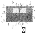
- the figure shows the outer wall 50 of a structure to be insulated, in particular a building, with an attached thermal insulation composite system 1 in a schematic cross-sectional view.
- the thermal insulation composite system 1 has numerous Insulating on each of two substantially flat and approximately parallel to each other major surfaces A, B are limited and which are attached to the outer wall 50 and cover them.
- the thermal insulation composite system 1 may comprise, in addition to the insulation boards, further layers, in particular a reinforcing layer covering the outside of the insulation boards and an outer plaster layer 70 covering the reinforcing layer.
- the illustrated insulation board 12 is part of an insulation element arrangement 10 according to the invention.
- the Dämmelementan extract 10 has, in addition to the insulation board 12, which forms the insulating element, a plurality of measuring sensors 21, 22, 31, 32 which are each attached to one of the main surfaces A, B of the insulation board 12.
- the insulation board 12 shown has a total of four measuring sensors, of which two (21, 22) are attached to the outer major surface A of the insulating board and two (31, 32) are fixed to the inner major surface B of the insulating board.
- the measuring sensors are not visible from the outside, since they are covered by the outer plaster layer 70 and are located between the insulating panel 12 and the outer wall 50.
- the measuring sensors are integrated into the insulation board 12 in such a way that the insulation board 12, like the remaining insulation boards of the composite thermal insulation system, can be mounted on the outer wall 50.
- the measuring sensors 21 and 31 are set up for temperature measurement, and the measuring sensors 22 and 32 are set up for measuring the humidity. Further measuring sensors for measuring other environmental parameters such as the heat flows can be provided. Alternatively, only one measuring sensor may be attached to the outer major surface and / or the inner major surface.
- the Dämmelementan extract further measuring sensors 41 and 42 which are mounted on the inside C of the outer wall 50 and which are adapted to measure the internal temperature (41) and the indoor humidity (42).
- the insulation board 12 has a passage 14 in a direction approximately perpendicular to the main surfaces A, B extending direction through which the connecting cables 16 of the attached to the outer major surface A measuring sensors 21, 22 are guided, and the outer wall 50 has a passage 51 in the form a hole through which the connection cables of both the outer main surface A and the inner major surface B mounted measuring sensors are guided. All connection cables are brought together in a junction box 55, which can be arranged on the inside of the outer wall 50.
- the connecting cables both at the outer main surface mounted measuring sensors 21, 22 (after the passage of the passage 16) and the connecting cables of the measuring sensors mounted on the inner main surface B may have a length which is greater than a thickness X of the outer wall 50, so that the connecting cables can be guided through the implementation 51 into the interior of the room.
- this length is greater than 0.5 m. more preferably about 1 m.
- connection cables can be connected to a signal processing device, which in turn can be connected to a display device 60.
- the display device serves to display the environmental parameters measured by the measuring sensors and / or to display insulation characteristics calculated therefrom.
- the display device may have a monitor hanging in the interior of a room on a wall, a display o. The like.
Landscapes
- Chemical & Material Sciences (AREA)
- Engineering & Computer Science (AREA)
- Combustion & Propulsion (AREA)
- Physics & Mathematics (AREA)
- General Physics & Mathematics (AREA)
- Building Environments (AREA)
- Testing Or Calibration Of Command Recording Devices (AREA)
- Investigating Or Analyzing Materials By The Use Of Electric Means (AREA)
- Investigating Or Analyzing Materials Using Thermal Means (AREA)
Applications Claiming Priority (1)
| Application Number | Priority Date | Filing Date | Title |
|---|---|---|---|
| DE202013005546U DE202013005546U1 (de) | 2013-06-19 | 2013-06-19 | Dämmelementanordnung |
Publications (2)
| Publication Number | Publication Date |
|---|---|
| EP2840371A2 true EP2840371A2 (fr) | 2015-02-25 |
| EP2840371A3 EP2840371A3 (fr) | 2015-06-03 |
Family
ID=48915663
Family Applications (1)
| Application Number | Title | Priority Date | Filing Date |
|---|---|---|---|
| EP14001909.2A Withdrawn EP2840371A3 (fr) | 2013-06-19 | 2014-06-02 | Ensemble d'éléments d'isolation |
Country Status (2)
| Country | Link |
|---|---|
| EP (1) | EP2840371A3 (fr) |
| DE (1) | DE202013005546U1 (fr) |
Families Citing this family (2)
| Publication number | Priority date | Publication date | Assignee | Title |
|---|---|---|---|---|
| DE202014001581U1 (de) | 2014-02-20 | 2014-04-03 | Bachl Dämmtechnik GmbH & Co. KG | Messsensorträger, Messsensorträgeranordnung und Messanordnung |
| DE102019000605B3 (de) * | 2019-01-30 | 2020-03-12 | Ewald Dörken Ag | Verwendung einer Sensorsystemanordnung im Baubereich und/oder Baugewerbe |
Citations (4)
| Publication number | Priority date | Publication date | Assignee | Title |
|---|---|---|---|---|
| DE69907430T2 (de) * | 1998-03-04 | 2003-12-24 | Masa-Therm S.A., Boudevilliers | Vorrichtung zum wärmeaustausch zwischen einer solarbeheizten platte und einer wand |
| WO2010007215A1 (fr) * | 2008-07-18 | 2010-01-21 | Vahanen International Oy | Procédé de déplacement d’énergie thermique et / ou d’humidité dans une structure de coque d’un bâtiment, et structure de coque |
| WO2012022393A2 (fr) | 2010-08-18 | 2012-02-23 | Schwenk Dämmtechnik Gmbh & Co. Kg | Élément d'isolation |
| US20120065789A1 (en) * | 2009-09-11 | 2012-03-15 | NetESCO LLC | Determining energy consumption in a structure |
Family Cites Families (3)
| Publication number | Priority date | Publication date | Assignee | Title |
|---|---|---|---|---|
| YU42759B (en) * | 1982-03-18 | 1988-12-31 | Ljubljana Avtomontaza | Heat power gauge |
| JPH0786437B2 (ja) * | 1992-05-15 | 1995-09-20 | 川惣電機工業株式会社 | 鋳造用モールドの熱流束検出方法及び装置 |
| US7831525B2 (en) * | 2008-09-08 | 2010-11-09 | International Business Machines Corporation | Automated energy transfer calculation and compensation |
-
2013
- 2013-06-19 DE DE202013005546U patent/DE202013005546U1/de not_active Expired - Lifetime
-
2014
- 2014-06-02 EP EP14001909.2A patent/EP2840371A3/fr not_active Withdrawn
Patent Citations (4)
| Publication number | Priority date | Publication date | Assignee | Title |
|---|---|---|---|---|
| DE69907430T2 (de) * | 1998-03-04 | 2003-12-24 | Masa-Therm S.A., Boudevilliers | Vorrichtung zum wärmeaustausch zwischen einer solarbeheizten platte und einer wand |
| WO2010007215A1 (fr) * | 2008-07-18 | 2010-01-21 | Vahanen International Oy | Procédé de déplacement d’énergie thermique et / ou d’humidité dans une structure de coque d’un bâtiment, et structure de coque |
| US20120065789A1 (en) * | 2009-09-11 | 2012-03-15 | NetESCO LLC | Determining energy consumption in a structure |
| WO2012022393A2 (fr) | 2010-08-18 | 2012-02-23 | Schwenk Dämmtechnik Gmbh & Co. Kg | Élément d'isolation |
Non-Patent Citations (1)
| Title |
|---|
| LUO C ET AL: "Modelling of wall heat transfer using modified conduction transfer function, finite volume and complex Fourier analysis methods", ENERGY AND BUILDINGS, LAUSANNE, CH, vol. 42, no. 5, 1 May 2010 (2010-05-01), pages 605 - 617, XP026964691, ISSN: 0378-7788, [retrieved on 20091110] * |
Also Published As
| Publication number | Publication date |
|---|---|
| DE202013005546U1 (de) | 2013-06-28 |
| EP2840371A3 (fr) | 2015-06-03 |
Similar Documents
| Publication | Publication Date | Title |
|---|---|---|
| AT515273B1 (de) | System zur Steuerung der Trocknungsphase von mit einer Fußbodenheizung versehenem Betonestrich | |
| DE102006010946B3 (de) | Außenlufttemperaturmesser mit einer Einrichtung zur Vermeidung von Fehlmessungen bei Starkwind | |
| EP2840371A2 (fr) | Ensemble d'éléments d'isolation | |
| EP3333330A1 (fr) | Dispositif de détection, en particulier dispositif de détection hygrothermique pour un système isolant d'enveloppe de bâtiment | |
| DE10030294A1 (de) | Verfahren zur Erfassung des Energieverbrauches und der Sanierungsbedürftigkeit eines Gebäudes | |
| DE3441733A1 (de) | Station zur aufnahme von geraetschaften, mess- oder regeleinrichtungen o.dgl. | |
| EP2149666A2 (fr) | Dispositif pour l'intégration d'un élément de protection extérieur destiné au recouvrement ou la libération au cas par cas d'une ouverture de mur | |
| WO1988000996A1 (fr) | Elements de panneaux prefabriques pour la realisation de chambres isolantes | |
| DE202010005189U1 (de) | Wärmedämmbauelement | |
| DE202009018102U1 (de) | Lichtschacht-Montagedämmplatte | |
| DE2208634C3 (de) | Vorrichtung zum Abstützen profilierter Dacheindeckungsplatten od. dgl | |
| DE102019106705A1 (de) | Heizmatte zur Verwendung in einem Fußbodenaufbau, Fußbodenaufbau und Verfahren zu dessen Herstellung | |
| EP4279683B1 (fr) | Dispositif de fixation d'au moins un objet sur une surface de toit | |
| DE202014103071U1 (de) | Rollladenkasten | |
| DE202010002768U1 (de) | Dämmelement für ein Untersparrendämmsystem | |
| DE102019220431B4 (de) | Vorrichtung zur Messung der hygrometrischen Feuchtigkeit in Baustoffen | |
| DE202008010857U1 (de) | Fugendichtungsband | |
| EP3147422B1 (fr) | Bandes d'isolation | |
| DE3230928A1 (de) | Vorrichtung zur herstellung einer dehnfuge | |
| EP0025428A2 (fr) | Isolation thermique pour murs | |
| DE202013105642U1 (de) | Dämmelement zur Verwendung in einem Wärmedämm-Verbundsystem | |
| DE102015118179A1 (de) | Wandmodul | |
| DE102022122700A1 (de) | Wanddurchführungseinheit und Außenwandgitter mit einer Abtropfleiste | |
| DE102013113864A1 (de) | Dämmelement zur Verwendung in einem Wärmedämm-Verbundsystem | |
| EP2634514B1 (fr) | Dispositif et procédé destinés à réaliser une étanchéification entre le mur et le sol au niveau de l'isolation dans des pièces |
Legal Events
| Date | Code | Title | Description |
|---|---|---|---|
| PUAI | Public reference made under article 153(3) epc to a published international application that has entered the european phase |
Free format text: ORIGINAL CODE: 0009012 |
|
| 17P | Request for examination filed |
Effective date: 20140602 |
|
| AK | Designated contracting states |
Kind code of ref document: A2 Designated state(s): AL AT BE BG CH CY CZ DE DK EE ES FI FR GB GR HR HU IE IS IT LI LT LU LV MC MK MT NL NO PL PT RO RS SE SI SK SM TR |
|
| AX | Request for extension of the european patent |
Extension state: BA ME |
|
| PUAL | Search report despatched |
Free format text: ORIGINAL CODE: 0009013 |
|
| AK | Designated contracting states |
Kind code of ref document: A3 Designated state(s): AL AT BE BG CH CY CZ DE DK EE ES FI FR GB GR HR HU IE IS IT LI LT LU LV MC MK MT NL NO PL PT RO RS SE SI SK SM TR |
|
| AX | Request for extension of the european patent |
Extension state: BA ME |
|
| RIC1 | Information provided on ipc code assigned before grant |
Ipc: G01K 17/20 20060101AFI20150429BHEP |
|
| 17Q | First examination report despatched |
Effective date: 20170403 |
|
| RIC1 | Information provided on ipc code assigned before grant |
Ipc: G01K 17/20 20060101AFI20180724BHEP Ipc: E04B 1/76 20060101ALI20180724BHEP |
|
| STAA | Information on the status of an ep patent application or granted ep patent |
Free format text: STATUS: THE APPLICATION IS DEEMED TO BE WITHDRAWN |
|
| 18D | Application deemed to be withdrawn |
Effective date: 20201023 |