EP2840374B1 - Obturateur de mesure pour un système de capteurs - Google Patents
Obturateur de mesure pour un système de capteurs Download PDFInfo
- Publication number
- EP2840374B1 EP2840374B1 EP14158893.9A EP14158893A EP2840374B1 EP 2840374 B1 EP2840374 B1 EP 2840374B1 EP 14158893 A EP14158893 A EP 14158893A EP 2840374 B1 EP2840374 B1 EP 2840374B1
- Authority
- EP
- European Patent Office
- Prior art keywords
- pressure
- sensor element
- hydraulic system
- inflow opening
- sensor
- Prior art date
- Legal status (The legal status is an assumption and is not a legal conclusion. Google has not performed a legal analysis and makes no representation as to the accuracy of the status listed.)
- Not-in-force
Links
Images


Classifications
-
- G—PHYSICS
- G01—MEASURING; TESTING
- G01L—MEASURING FORCE, STRESS, TORQUE, WORK, MECHANICAL POWER, MECHANICAL EFFICIENCY, OR FLUID PRESSURE
- G01L19/00—Details of, or accessories for, apparatus for measuring steady or quasi-steady pressure of a fluent medium insofar as such details or accessories are not special to particular types of pressure gauges
- G01L19/06—Means for preventing overload or deleterious influence of the measured medium on the measuring device or vice versa
- G01L19/0618—Overload protection
Definitions
- the present invention relates to a sensor arrangement with an orifice plate for preventing damage to pressure sensors by pressure peaks.
- Hydraulic line systems in particular for automobiles, have sensors at various positions in the hydraulic line system, in particular pressure sensors, which are set up to determine a pressure that prevails locally or globally in the hydraulic system, in order to pass on this determined pressure value to a control device.
- the control unit can trigger actions in the vehicle based on the determined pressure value.
- a detected pressure value may be used to detect a correct function or possible malfunction of a hydraulic system in a vehicle and further determine a possible malfunction of vehicle components connected to the hydraulic system.
- pressure peaks can damage measuring elements, for example pressure sensors of the hydraulic line system.
- the damage can be reduced or avoided by, for example, provided between a sensor element and the hydraulic line system, an element which dampens the transmission of such a pressure pulse and thus may reduce pressure peaks.
- FIG. 1 shows an example of such a configuration in which a pressure sensor shown schematically with measuring port 2 is connected using a header plate 4 to a hydraulic line system 10.
- a diaphragm with small openings for example in the range of 0.2-0.3 mm, which can on the one hand pass slow pressure fluctuations in the hydraulic line system, so that the associated hydraulic line pressure from the pressure sensor 2 is detectable, while pressure peaks due to the design and in particular size of the openings 6 of the aperture only delayed or attenuated passed become.
- aperture openings are according to FIG. 1 usually introduced in a second manufacturing step in the front plate 4, for example by drilling and the like.
- the necessary for the function hole size of the apertures 6 is at a few tenths of millimeters. In machining production incurred by inevitable and especially due to the hole size frequent drill breakage high costs. When making the attachment plate, for example with an injection molding tool, this is very susceptible to wear and breakage in this area.
- a pressure sensor in which a component designed as a stamped bent part is fastened via resilient webs to a groove of a housing, so that the component acts as a throttle disk.
- a shock absorber for membranes which has a throttle body with at least two passageways, so that a flowing through the throttle body medium is decomposed into a plurality of jets.
- One aspect of the present invention may be seen to provide a simplified orifice function for a pressure sensor, particularly with reduced manufacturing overhead.
- the orifice plate according to the invention allows a more favorable production through the use of simpler geometries, whereby more robust tools can be used for the production.
- the channel or the apertures which are conventionally designed as a completely closed channel with inlet and outlet openings, are modified to the effect that these apertures or inlet openings of the hydraulic medium to the pressure sensor no longer constitute a closed channel or closed pressure transmission line. but rather is realized as a non-closed pressure transmission line, for example as an on-cut channel, which is only so closed with a further element, such as the housing of the pressure sensor itself, so that forms the (closed) pressure transmission line between the hydraulic system and pressure sensor.
- a non-closed inlet opening is introduced from one side of the orifice, for example, a substantially semicircular channel or groove, wherein the function of the pressure transmission line is achieved in that a suitably designed surface of another element with the substantially planar surface of the orifice with its groove or depression comes to rest, so that only a closed pressure transmission line (for example, with a semicircular cross section) is formed by the further element.
- a closed pressure transmission line for example, with a semicircular cross section
- the non-closed pressure transmission line thus has the form of an open in its longitudinal direction, eg halved channel. Furthermore, the non-closed pressure transmission line on inlet and outlet opening (s), which, however, only through the contact or the conclusion of the non-closed pressure transmission line with the other element form an opening in the conventional sense, such as the opening a pipe or channel. Also, an opening of the non-closed pressure transmission line can be realized substantially in that the further element at the desired or required location of the opening itself has an opening, so that at this point a hydraulic medium in the / from the completed with the other element , but itself or on its own non-closed pressure transmission line can enter / exit.
- an orifice plate for a pressure sensor or in a, e.g. the upper surface of an attachment plate for the pressure sensor is a groove introduced.
- the effective diaphragm cross-section is generated by the attachment plate rests against the end face of a pressure sensor and thus the non-closed pressure transmission line or groove is transformed into a closed pressure transmission line by the pressure sensor.
- the access of the hydraulic medium into a reservoir of the attachment plate can be provided by inlet openings in the attachment plate, whose connection cross-section can be comparatively large, since these no longer have to have a pressure peak reduction functionality. These openings through the attachment plate in the reservoir can thus be designed much coarser and easier to produce.
- FIG. 2 An exemplary embodiment of an orifice plate and attachment plate according to the present invention is shown.
- FIG. 2 shows a schematic structure of an attachment plate 28 according to the invention with an orifice plate 20.
- a reservoir 26 is provided, in which hydraulic medium can accumulate via inlet openings 24.
- the actual inlet or the actual pressure transmission line 22 to a arranged on the attachment plate 28 sensor element 2 via pressure transmission line 22, exemplified as a semi-circular groove.
- a sensor element 2 is applied with its end face on the surface of the header plate 28 and orifice plate 20 so that the inlet is located in the sensor element 2 in the central region of the orifice in the pressure transmission line 22, there is an inflow and outflow of hydraulic fluid exclusively via the relatively small openings 30, which are directed laterally of the orifice in the reservoir 26.
- FIG. 3 In this case, the arrangement of the attachment plate 28 and the orifice plate 20 with a sensor element 2. Sensor element 2 is thus applied to the intent plate 28 and the orifice plate 20 so that with the lower surface of the sensor element 2, a channel 22 is formed in the plane, which realizes the comparatively small opening 30, which in turn is adapted to pass on pressure fluctuations or pressure peaks in the hydraulic line system only delayed or damped to the sensor element 20.
- the comparatively large inlet opening 24 which is thus much easier to produce and can be made more robust.
- Characterized in that the pressure transmission line 22 can be produced by a robust and comparatively easy to produce surface variation of a mold, the mold is also more robust and has a longer service life.
- the housing of the sensor element 2 and the attachment plate 28 is sealed using a sealing element 32, for example an O-ring.
- a sealing element 32 for example an O-ring.
- the attachment of sensor element 2 and attachment plate 28 to each other is in FIG. 3 not shown in detail.
- Hydraulic system 10 is in turn connected to the underside. It may be decisive for the function that the attachment plate rests well against the pressure sensor end face. This may be ensured by applying an axial force to the pressure sensor, for example by a pressure spring which presses the components onto the hydraulic connection. Alternatively, a positive, positive or cohesive connection of the attachment plate can be realized with the pressure sensor.
- the production of the pressure transmission line 22 can be carried out by molding with an injection mold in the case that the intent plate or the orifice plate consists of a plastic material. Alternatively, shaping may be done by a die casting tool if the header plate and / or the orifice plate are made of a suitable metal. A post-processing may not be necessary, but can be done to optimize the function. Alternatively, a machining or embossing in metal parts is conceivable.
- An orifice plate 20 according to the invention or its pressure transmission line (s) 22 can be produced in particular in one or the same production step as the element itself. Thus, in particular, no introduction of the inlet opening in a second production step, e.g. by drilling or the like, necessary. The production of the orifice plate according to the invention or attachment plate is thus much easier and cheaper to produce.
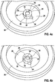
- FIGS. 4a, b Exemplary embodiments of the orifice plate and the pressure transmission line according to the present invention are shown.
- Geometric embodiments of the pressure transmission line 22 are, for example, two opposite effective apertures, as in FIG. 2 shown. Alternatively, only one aperture can be provided, while the second side of the pressure transmission line 22 is closed. Alternatively, a plurality of apertures, in particular more than two effective apertures 30 can be provided, which are formed, for example, by a star-shaped groove guide of the pressure transmission line 22 to the measuring aperture of the sensor element.
- the throttle orifices have a larger volume 34 in the middle of the inlet opening or measuring opening to the pressure sensor, for example a blind hole.
- a centering of the diaphragm geometry of the orifice plate 20 under the measuring orifice of the sensor element 2 may be easier to realize because this may reduce a required accuracy.
- the energy of a pressure pulse may also be better absorbed.
- the pressure transmission lines of FIG. 4a are exemplarily designed as short linear sections.
- the pressure transmission lines 22, as in FIG. 4b shown also non-linear, for example, curved, curved or meandering. They thus do not run directly to the connection point of the pressure sensor, but are kinked one or more times or curved in order to reduce the energy of a pressure pulse better.
Landscapes
- Physics & Mathematics (AREA)
- General Physics & Mathematics (AREA)
- Measuring Fluid Pressure (AREA)
- Control Of Transmission Device (AREA)
Claims (2)
- Agencement de capteur, présentant :un diaphragme d'étranglement (20) avec une ouverture d'alimentation (30) pour un fluide de transfert ;et un élément de capteur (2) ;l'ouverture d'alimentation (30) étant prévue pour amortir des pointes de pression ou des variations de pression dans un système hydraulique (10) vers l'élément de capteur (2),l'ouverture d'alimentation (30) constituant au moins une rainure de forme semi-circulaire s'étendant entre le système hydraulique (10) et une alimentation à l'élément de capteur (2),caractérisé en ce que l'agencement de capteur présente une plaque d'habillage (28), la plaque d'habillage (28) produisant, entre le système hydraulique (10) et le diaphragme d'étranglement (20), au moins une deuxième ouverture d'alimentation (24) et un volume (26), qui amortit de manière réduite par rapport au diaphragme d'étranglement des pointes de pression ou des variations de pression dans le système hydraulique vers l'élément de capteur, l'au moins une deuxième ouverture d'alimentation (24) étant accouplée au système hydraulique (10) et le volume (26) étant disposé entre l'au moins une deuxième ouverture d'alimentation (24) et l'ouverture d'alimentation (30) et la rainure de forme semi-circulaire constituant avec une surface de l'élément de capteur (2) une conduite de transfert de pression fermée (22) avec une ouverture d'entrée et une ouverture de sortie, de telle sorte qu'une pression puisse être transmise du système hydraulique à l'élément de capteur, et en ce que la plaque d'habillage (28) et le diaphragme d'étranglement (20) sont réalisés d'une seule pièce.
- Agencement de capteur selon la revendication 1, dans lequel le diaphragme d'étranglement (20) est fabriqué au moyen d'un procédé de moulage par injection, d'un procédé de coulée, d'un usinage par enlèvement de copeaux ou d'une opération d'estampage.
Applications Claiming Priority (1)
| Application Number | Priority Date | Filing Date | Title |
|---|---|---|---|
| DE201310208276 DE102013208276A1 (de) | 2013-05-06 | 2013-05-06 | Drosselblende für eine Sensoranordnung |
Publications (3)
| Publication Number | Publication Date |
|---|---|
| EP2840374A2 EP2840374A2 (fr) | 2015-02-25 |
| EP2840374A3 EP2840374A3 (fr) | 2015-04-08 |
| EP2840374B1 true EP2840374B1 (fr) | 2018-09-12 |
Family
ID=50272378
Family Applications (1)
| Application Number | Title | Priority Date | Filing Date |
|---|---|---|---|
| EP14158893.9A Not-in-force EP2840374B1 (fr) | 2013-05-06 | 2014-03-11 | Obturateur de mesure pour un système de capteurs |
Country Status (2)
| Country | Link |
|---|---|
| EP (1) | EP2840374B1 (fr) |
| DE (1) | DE102013208276A1 (fr) |
Families Citing this family (1)
| Publication number | Priority date | Publication date | Assignee | Title |
|---|---|---|---|---|
| DE102015224474A1 (de) | 2015-12-07 | 2017-06-08 | Robert Bosch Gmbh | Verfahren zur Herstellung einer Vorrichtung zur Erfassung mindestens einer Eigenschaft eines fluiden Mediums in einem Messraum |
Family Cites Families (3)
| Publication number | Priority date | Publication date | Assignee | Title |
|---|---|---|---|---|
| DE830142C (de) * | 1950-10-21 | 1952-01-31 | Martin Vermoehlen | Stossdaempfer fuer durch Fluessigkeit oder Gas belastete Membrane |
| DE102004025339B4 (de) * | 2004-05-19 | 2007-09-06 | Ifm Electronic Gmbh | Drucksensor |
| DE102010001963B4 (de) * | 2010-02-16 | 2026-04-02 | Robert Bosch Gmbh | Vorrichtung zur Verminderung von Druckpulsen bei Drucksensoren |
-
2013
- 2013-05-06 DE DE201310208276 patent/DE102013208276A1/de not_active Withdrawn
-
2014
- 2014-03-11 EP EP14158893.9A patent/EP2840374B1/fr not_active Not-in-force
Non-Patent Citations (1)
| Title |
|---|
| None * |
Also Published As
| Publication number | Publication date |
|---|---|
| DE102013208276A1 (de) | 2014-11-06 |
| EP2840374A3 (fr) | 2015-04-08 |
| EP2840374A2 (fr) | 2015-02-25 |
Similar Documents
| Publication | Publication Date | Title |
|---|---|---|
| EP3551512B1 (fr) | Arrangement de maître-cylindre avec un capteur de position et arrangement d'étanchéité | |
| DE19914557B4 (de) | Kolben für einen Kolben-Zylinder-Aggregat | |
| EP2829782B1 (fr) | Selle pour un raccord de dérivation | |
| DE102008042624A1 (de) | Schieberventil zur hydraulischen Steuerung in einem Kraftfahrzeug-Automatikgetriebe | |
| EP2245277B1 (fr) | Insert de guidage de fluide sous pression destiné à une soupape de commande dans un dispositif d'actionnment hydraulique | |
| DE102008033269A1 (de) | Rückschlagventil | |
| DE102005038341A1 (de) | Hydrostatische Profilschienenführung | |
| DE102015110733A1 (de) | Ventil, insbesondere Hydraulikventil | |
| DE102014207464B4 (de) | Verstellbare Dämpfventileinrichtung | |
| WO2015132043A1 (fr) | Soupape destinée notamment à un amortisseur de vibrations | |
| DE102004050732A1 (de) | Dämpfventileinrichtung mit progressiver Dämpfkraftkennlinie | |
| DE102010035058A1 (de) | Schmierölversorgungseinrichtung für ein Wälzlager | |
| EP2840374A2 (fr) | Obturateur de mesure pour un système de capteurs | |
| EP2009255B1 (fr) | Valve d'étranglement pour un moteur à combustion interne doté d'une commande de soupape hydroélectrique | |
| DE102014004670A1 (de) | Ventil | |
| DE102009052076A1 (de) | Ventilanordnung | |
| DE102014206968A1 (de) | Hochdruckpumpe und Hochdruckrichtungsventil | |
| WO2010031555A1 (fr) | Ensemble boîte de vitesses | |
| DE102005019312B4 (de) | Ventil zum Steuern eines Fluids | |
| DE102005009151B4 (de) | Einrohrschwingungsdämpfer | |
| EP3379118B1 (fr) | Clapet anti-retour | |
| DE102007056687A1 (de) | Luftfeder | |
| DE10208996B4 (de) | Elektromagnetventil | |
| DE102014222480A1 (de) | Kolbenbaugruppe, insbesondere für eine Kolbenpumpe eines Hydraulikaggregats eines Kraftfahrzeugs bzw. Kolbenpumpe | |
| DE102019120227A1 (de) | Ventil und Vorrichtung zur Regelung von Drücken eines Strömungsmittels mit dem Ventil sowie Vorrichtung zur Sicherung des Ventils in dem Getriebebauteil |
Legal Events
| Date | Code | Title | Description |
|---|---|---|---|
| PUAI | Public reference made under article 153(3) epc to a published international application that has entered the european phase |
Free format text: ORIGINAL CODE: 0009012 |
|
| 17P | Request for examination filed |
Effective date: 20140311 |
|
| AK | Designated contracting states |
Kind code of ref document: A2 Designated state(s): AL AT BE BG CH CY CZ DE DK EE ES FI FR GB GR HR HU IE IS IT LI LT LU LV MC MK MT NL NO PL PT RO RS SE SI SK SM TR |
|
| AX | Request for extension of the european patent |
Extension state: BA ME |
|
| PUAL | Search report despatched |
Free format text: ORIGINAL CODE: 0009013 |
|
| AK | Designated contracting states |
Kind code of ref document: A3 Designated state(s): AL AT BE BG CH CY CZ DE DK EE ES FI FR GB GR HR HU IE IS IT LI LT LU LV MC MK MT NL NO PL PT RO RS SE SI SK SM TR |
|
| AX | Request for extension of the european patent |
Extension state: BA ME |
|
| RIC1 | Information provided on ipc code assigned before grant |
Ipc: G01L 19/06 20060101AFI20150303BHEP |
|
| R17P | Request for examination filed (corrected) |
Effective date: 20151008 |
|
| RBV | Designated contracting states (corrected) |
Designated state(s): AL AT BE BG CH CY CZ DE DK EE ES FI FR GB GR HR HU IE IS IT LI LT LU LV MC MK MT NL NO PL PT RO RS SE SI SK SM TR |
|
| GRAP | Despatch of communication of intention to grant a patent |
Free format text: ORIGINAL CODE: EPIDOSNIGR1 |
|
| STAA | Information on the status of an ep patent application or granted ep patent |
Free format text: STATUS: GRANT OF PATENT IS INTENDED |
|
| INTG | Intention to grant announced |
Effective date: 20180515 |
|
| GRAS | Grant fee paid |
Free format text: ORIGINAL CODE: EPIDOSNIGR3 |
|
| GRAA | (expected) grant |
Free format text: ORIGINAL CODE: 0009210 |
|
| STAA | Information on the status of an ep patent application or granted ep patent |
Free format text: STATUS: THE PATENT HAS BEEN GRANTED |
|
| AK | Designated contracting states |
Kind code of ref document: B1 Designated state(s): AL AT BE BG CH CY CZ DE DK EE ES FI FR GB GR HR HU IE IS IT LI LT LU LV MC MK MT NL NO PL PT RO RS SE SI SK SM TR |
|
| REG | Reference to a national code |
Ref country code: GB Ref legal event code: FG4D Free format text: NOT ENGLISH |
|
| REG | Reference to a national code |
Ref country code: CH Ref legal event code: EP |
|
| REG | Reference to a national code |
Ref country code: IE Ref legal event code: FG4D Free format text: LANGUAGE OF EP DOCUMENT: GERMAN |
|
| REG | Reference to a national code |
Ref country code: DE Ref legal event code: R096 Ref document number: 502014009424 Country of ref document: DE |
|
| REG | Reference to a national code |
Ref country code: AT Ref legal event code: REF Ref document number: 1041183 Country of ref document: AT Kind code of ref document: T Effective date: 20181015 |
|
| REG | Reference to a national code |
Ref country code: NL Ref legal event code: MP Effective date: 20180912 |
|
| REG | Reference to a national code |
Ref country code: LT Ref legal event code: MG4D |
|
| PG25 | Lapsed in a contracting state [announced via postgrant information from national office to epo] |
Ref country code: FI Free format text: LAPSE BECAUSE OF FAILURE TO SUBMIT A TRANSLATION OF THE DESCRIPTION OR TO PAY THE FEE WITHIN THE PRESCRIBED TIME-LIMIT Effective date: 20180912 Ref country code: SE Free format text: LAPSE BECAUSE OF FAILURE TO SUBMIT A TRANSLATION OF THE DESCRIPTION OR TO PAY THE FEE WITHIN THE PRESCRIBED TIME-LIMIT Effective date: 20180912 Ref country code: RS Free format text: LAPSE BECAUSE OF FAILURE TO SUBMIT A TRANSLATION OF THE DESCRIPTION OR TO PAY THE FEE WITHIN THE PRESCRIBED TIME-LIMIT Effective date: 20180912 Ref country code: GR Free format text: LAPSE BECAUSE OF FAILURE TO SUBMIT A TRANSLATION OF THE DESCRIPTION OR TO PAY THE FEE WITHIN THE PRESCRIBED TIME-LIMIT Effective date: 20181213 Ref country code: NO Free format text: LAPSE BECAUSE OF FAILURE TO SUBMIT A TRANSLATION OF THE DESCRIPTION OR TO PAY THE FEE WITHIN THE PRESCRIBED TIME-LIMIT Effective date: 20181212 Ref country code: LT Free format text: LAPSE BECAUSE OF FAILURE TO SUBMIT A TRANSLATION OF THE DESCRIPTION OR TO PAY THE FEE WITHIN THE PRESCRIBED TIME-LIMIT Effective date: 20180912 Ref country code: BG Free format text: LAPSE BECAUSE OF FAILURE TO SUBMIT A TRANSLATION OF THE DESCRIPTION OR TO PAY THE FEE WITHIN THE PRESCRIBED TIME-LIMIT Effective date: 20181212 |
|
| PG25 | Lapsed in a contracting state [announced via postgrant information from national office to epo] |
Ref country code: LV Free format text: LAPSE BECAUSE OF FAILURE TO SUBMIT A TRANSLATION OF THE DESCRIPTION OR TO PAY THE FEE WITHIN THE PRESCRIBED TIME-LIMIT Effective date: 20180912 Ref country code: HR Free format text: LAPSE BECAUSE OF FAILURE TO SUBMIT A TRANSLATION OF THE DESCRIPTION OR TO PAY THE FEE WITHIN THE PRESCRIBED TIME-LIMIT Effective date: 20180912 Ref country code: AL Free format text: LAPSE BECAUSE OF FAILURE TO SUBMIT A TRANSLATION OF THE DESCRIPTION OR TO PAY THE FEE WITHIN THE PRESCRIBED TIME-LIMIT Effective date: 20180912 |
|
| PG25 | Lapsed in a contracting state [announced via postgrant information from national office to epo] |
Ref country code: IS Free format text: LAPSE BECAUSE OF FAILURE TO SUBMIT A TRANSLATION OF THE DESCRIPTION OR TO PAY THE FEE WITHIN THE PRESCRIBED TIME-LIMIT Effective date: 20190112 Ref country code: RO Free format text: LAPSE BECAUSE OF FAILURE TO SUBMIT A TRANSLATION OF THE DESCRIPTION OR TO PAY THE FEE WITHIN THE PRESCRIBED TIME-LIMIT Effective date: 20180912 Ref country code: NL Free format text: LAPSE BECAUSE OF FAILURE TO SUBMIT A TRANSLATION OF THE DESCRIPTION OR TO PAY THE FEE WITHIN THE PRESCRIBED TIME-LIMIT Effective date: 20180912 Ref country code: CZ Free format text: LAPSE BECAUSE OF FAILURE TO SUBMIT A TRANSLATION OF THE DESCRIPTION OR TO PAY THE FEE WITHIN THE PRESCRIBED TIME-LIMIT Effective date: 20180912 Ref country code: ES Free format text: LAPSE BECAUSE OF FAILURE TO SUBMIT A TRANSLATION OF THE DESCRIPTION OR TO PAY THE FEE WITHIN THE PRESCRIBED TIME-LIMIT Effective date: 20180912 Ref country code: EE Free format text: LAPSE BECAUSE OF FAILURE TO SUBMIT A TRANSLATION OF THE DESCRIPTION OR TO PAY THE FEE WITHIN THE PRESCRIBED TIME-LIMIT Effective date: 20180912 Ref country code: PL Free format text: LAPSE BECAUSE OF FAILURE TO SUBMIT A TRANSLATION OF THE DESCRIPTION OR TO PAY THE FEE WITHIN THE PRESCRIBED TIME-LIMIT Effective date: 20180912 Ref country code: IT Free format text: LAPSE BECAUSE OF FAILURE TO SUBMIT A TRANSLATION OF THE DESCRIPTION OR TO PAY THE FEE WITHIN THE PRESCRIBED TIME-LIMIT Effective date: 20180912 |
|
| PG25 | Lapsed in a contracting state [announced via postgrant information from national office to epo] |
Ref country code: SK Free format text: LAPSE BECAUSE OF FAILURE TO SUBMIT A TRANSLATION OF THE DESCRIPTION OR TO PAY THE FEE WITHIN THE PRESCRIBED TIME-LIMIT Effective date: 20180912 Ref country code: PT Free format text: LAPSE BECAUSE OF FAILURE TO SUBMIT A TRANSLATION OF THE DESCRIPTION OR TO PAY THE FEE WITHIN THE PRESCRIBED TIME-LIMIT Effective date: 20190112 Ref country code: SM Free format text: LAPSE BECAUSE OF FAILURE TO SUBMIT A TRANSLATION OF THE DESCRIPTION OR TO PAY THE FEE WITHIN THE PRESCRIBED TIME-LIMIT Effective date: 20180912 |
|
| REG | Reference to a national code |
Ref country code: DE Ref legal event code: R097 Ref document number: 502014009424 Country of ref document: DE |
|
| PLBE | No opposition filed within time limit |
Free format text: ORIGINAL CODE: 0009261 |
|
| STAA | Information on the status of an ep patent application or granted ep patent |
Free format text: STATUS: NO OPPOSITION FILED WITHIN TIME LIMIT |
|
| PG25 | Lapsed in a contracting state [announced via postgrant information from national office to epo] |
Ref country code: DK Free format text: LAPSE BECAUSE OF FAILURE TO SUBMIT A TRANSLATION OF THE DESCRIPTION OR TO PAY THE FEE WITHIN THE PRESCRIBED TIME-LIMIT Effective date: 20180912 |
|
| 26N | No opposition filed |
Effective date: 20190613 |
|
| PG25 | Lapsed in a contracting state [announced via postgrant information from national office to epo] |
Ref country code: SI Free format text: LAPSE BECAUSE OF FAILURE TO SUBMIT A TRANSLATION OF THE DESCRIPTION OR TO PAY THE FEE WITHIN THE PRESCRIBED TIME-LIMIT Effective date: 20180912 |
|
| PG25 | Lapsed in a contracting state [announced via postgrant information from national office to epo] |
Ref country code: MC Free format text: LAPSE BECAUSE OF FAILURE TO SUBMIT A TRANSLATION OF THE DESCRIPTION OR TO PAY THE FEE WITHIN THE PRESCRIBED TIME-LIMIT Effective date: 20180912 |
|
| REG | Reference to a national code |
Ref country code: CH Ref legal event code: PL |
|
| GBPC | Gb: european patent ceased through non-payment of renewal fee |
Effective date: 20190311 |
|
| PG25 | Lapsed in a contracting state [announced via postgrant information from national office to epo] |
Ref country code: LU Free format text: LAPSE BECAUSE OF NON-PAYMENT OF DUE FEES Effective date: 20190311 |
|
| REG | Reference to a national code |
Ref country code: BE Ref legal event code: MM Effective date: 20190331 |
|
| PG25 | Lapsed in a contracting state [announced via postgrant information from national office to epo] |
Ref country code: CH Free format text: LAPSE BECAUSE OF NON-PAYMENT OF DUE FEES Effective date: 20190331 Ref country code: LI Free format text: LAPSE BECAUSE OF NON-PAYMENT OF DUE FEES Effective date: 20190331 Ref country code: GB Free format text: LAPSE BECAUSE OF NON-PAYMENT OF DUE FEES Effective date: 20190311 Ref country code: IE Free format text: LAPSE BECAUSE OF NON-PAYMENT OF DUE FEES Effective date: 20190311 |
|
| PG25 | Lapsed in a contracting state [announced via postgrant information from national office to epo] |
Ref country code: BE Free format text: LAPSE BECAUSE OF NON-PAYMENT OF DUE FEES Effective date: 20190331 Ref country code: FR Free format text: LAPSE BECAUSE OF NON-PAYMENT OF DUE FEES Effective date: 20190331 |
|
| PG25 | Lapsed in a contracting state [announced via postgrant information from national office to epo] |
Ref country code: TR Free format text: LAPSE BECAUSE OF FAILURE TO SUBMIT A TRANSLATION OF THE DESCRIPTION OR TO PAY THE FEE WITHIN THE PRESCRIBED TIME-LIMIT Effective date: 20180912 |
|
| PG25 | Lapsed in a contracting state [announced via postgrant information from national office to epo] |
Ref country code: MT Free format text: LAPSE BECAUSE OF FAILURE TO SUBMIT A TRANSLATION OF THE DESCRIPTION OR TO PAY THE FEE WITHIN THE PRESCRIBED TIME-LIMIT Effective date: 20180912 |
|
| REG | Reference to a national code |
Ref country code: AT Ref legal event code: MM01 Ref document number: 1041183 Country of ref document: AT Kind code of ref document: T Effective date: 20190311 |
|
| PG25 | Lapsed in a contracting state [announced via postgrant information from national office to epo] |
Ref country code: AT Free format text: LAPSE BECAUSE OF NON-PAYMENT OF DUE FEES Effective date: 20190311 |
|
| PG25 | Lapsed in a contracting state [announced via postgrant information from national office to epo] |
Ref country code: CY Free format text: LAPSE BECAUSE OF FAILURE TO SUBMIT A TRANSLATION OF THE DESCRIPTION OR TO PAY THE FEE WITHIN THE PRESCRIBED TIME-LIMIT Effective date: 20180912 |
|
| PG25 | Lapsed in a contracting state [announced via postgrant information from national office to epo] |
Ref country code: HU Free format text: LAPSE BECAUSE OF FAILURE TO SUBMIT A TRANSLATION OF THE DESCRIPTION OR TO PAY THE FEE WITHIN THE PRESCRIBED TIME-LIMIT; INVALID AB INITIO Effective date: 20140311 |
|
| PG25 | Lapsed in a contracting state [announced via postgrant information from national office to epo] |
Ref country code: MK Free format text: LAPSE BECAUSE OF FAILURE TO SUBMIT A TRANSLATION OF THE DESCRIPTION OR TO PAY THE FEE WITHIN THE PRESCRIBED TIME-LIMIT Effective date: 20180912 |
|
| PGFP | Annual fee paid to national office [announced via postgrant information from national office to epo] |
Ref country code: DE Payment date: 20240527 Year of fee payment: 11 |
|
| REG | Reference to a national code |
Ref country code: DE Ref legal event code: R119 Ref document number: 502014009424 Country of ref document: DE |
|
| PG25 | Lapsed in a contracting state [announced via postgrant information from national office to epo] |
Ref country code: DE Free format text: LAPSE BECAUSE OF NON-PAYMENT OF DUE FEES Effective date: 20251001 |