EP2840411B1 - Echtzeit-Fehlererkennung bei einem Instrumentenlandesystem - Google Patents
Echtzeit-Fehlererkennung bei einem Instrumentenlandesystem Download PDFInfo
- Publication number
- EP2840411B1 EP2840411B1 EP14173998.7A EP14173998A EP2840411B1 EP 2840411 B1 EP2840411 B1 EP 2840411B1 EP 14173998 A EP14173998 A EP 14173998A EP 2840411 B1 EP2840411 B1 EP 2840411B1
- Authority
- EP
- European Patent Office
- Prior art keywords
- band
- signal
- test signal
- receiver
- converter
- Prior art date
- Legal status (The legal status is an assumption and is not a legal conclusion. Google has not performed a legal analysis and makes no representation as to the accuracy of the status listed.)
- Active
Links
Images


Classifications
-
- G—PHYSICS
- G01—MEASURING; TESTING
- G01S—RADIO DIRECTION-FINDING; RADIO NAVIGATION; DETERMINING DISTANCE OR VELOCITY BY USE OF RADIO WAVES; LOCATING OR PRESENCE-DETECTING BY USE OF THE REFLECTION OR RERADIATION OF RADIO WAVES; ANALOGOUS ARRANGEMENTS USING OTHER WAVES
- G01S1/00—Beacons or beacon systems transmitting signals having a characteristic or characteristics capable of being detected by non-directional receivers and defining directions, positions, or position lines fixed relatively to the beacon transmitters; Receivers co-operating therewith
- G01S1/02—Beacons or beacon systems transmitting signals having a characteristic or characteristics capable of being detected by non-directional receivers and defining directions, positions, or position lines fixed relatively to the beacon transmitters; Receivers co-operating therewith using radio waves
- G01S1/022—Means for monitoring or calibrating
- G01S1/026—Means for monitoring or calibrating of associated receivers
-
- G—PHYSICS
- G08—SIGNALLING
- G08G—TRAFFIC CONTROL SYSTEMS
- G08G5/00—Traffic control systems for aircraft
- G08G5/50—Navigation or guidance aids
- G08G5/54—Navigation or guidance aids for approach or landing
-
- G—PHYSICS
- G01—MEASURING; TESTING
- G01S—RADIO DIRECTION-FINDING; RADIO NAVIGATION; DETERMINING DISTANCE OR VELOCITY BY USE OF RADIO WAVES; LOCATING OR PRESENCE-DETECTING BY USE OF THE REFLECTION OR RERADIATION OF RADIO WAVES; ANALOGOUS ARRANGEMENTS USING OTHER WAVES
- G01S1/00—Beacons or beacon systems transmitting signals having a characteristic or characteristics capable of being detected by non-directional receivers and defining directions, positions, or position lines fixed relatively to the beacon transmitters; Receivers co-operating therewith
- G01S1/02—Beacons or beacon systems transmitting signals having a characteristic or characteristics capable of being detected by non-directional receivers and defining directions, positions, or position lines fixed relatively to the beacon transmitters; Receivers co-operating therewith using radio waves
- G01S1/08—Systems for determining direction or position line
- G01S1/14—Systems for determining direction or position line using amplitude comparison of signals transmitted simultaneously from antennas or antenna systems having differently oriented overlapping directivity-characteristics
Definitions
- An instrument landing system is a ground-based system that provides precision guidance to an aircraft approaching and landing on a runway.
- the ILS uses Very High Frequency (VHF) and Ultra High Frequency (UHF) guidance signals to enable a safe landing during conditions such as low ceilings or reduced visibility due to fog, rain, or blowing snow.
- VHF Very High Frequency
- UHF Ultra High Frequency
- the ILS includes ground-based transmitters that transmit the guidance signals to a receiver on-board the aircraft.
- the guidance signals produce ILS navigation outputs that are used by the flight control system to bring the aircraft to a safe landing on the runway.
- ILS receiver signal processing may result in mission failure that could have catastrophic consequences.
- conventional systems have built-in fault detection capabilities.
- Some on-board ILS receivers detect possible malfunctions using two or more identical receiver paths, coupled to a shared antenna, and tuned to the same radio channel containing the ILS guidance signal broadcasted by the ILS ground station.
- Each ILS receiver path performs identical, or near-identical, computations on the same input signal to produce the ILS radio guidance data.
- a malfunction is detected when ILS receiver paths produce different guidance data.
- the drawback of this approach is the cost associated with employing additional full receiver paths and the reduction in receiver sensitivity associated with splitting the antenna output into multiple inputs for each of the receivers which cuts down on the maximum range at which the guidance signals can be detected.
- Another approach favored by the large airplane manufacturers is to feed a single on-board receiver from an antenna to demodulate the desired guidance signals and then digitize the demodulated signal in two parallel digital processing chains to produce the radio guidance data.
- the processors compare their guidance data to detect any malfunction in the digital processing chain in real-time.
- signals whose malfunction may cause erroneous data are also monitored in real-time.
- a test signal is injected into the RF receiver input during all phases of flight during which the landing guidance signal is not to be received, and signal processors monitor the test signal to detect any malfunction in the RF chain up until the landing final phase of flight is started.
- the drawback of this approach is that any malfunctions in RF components that cannot be monitored during final approach and landing can result in a loss of guidance.
- a method which provides the capability to detect any receiver malfunction in real-time without added parts count and without degrading the receiver sensitivity/ maximum detection range would be highly desirable.
- US3820115A discloses a radio receiver for navigational or guidance of aircraft, including a channel of conventional processing circuits for processing the received radio signals to activate a course indicator, circuitry for superimposing rider signals on the received radio signals near the input end of the channel, apparatus for comparing the rider signals after processing through the channel with their original form, and an alarm indicator for indicating selected differences between the compared signals.
- US3750176A discloses an integrity monitor for an aircraft Instrument Landing System receiver in which malfunctions are detected by comparing the outputs of identical guidance signal channels. Tracer signals are injected to prevent total guidance channel failure from being mistaken as a valid condition. Automatic means adjust comparison tolerances to permit a greater difference in guidance channel outputs without alarm when the aircraft is in the clearance area and to reduce the permissible difference when the aircraft is on-course.
- the present invention provides a receiver for an instrument landing system, according to claim 1 of the appended claims.
- the invention further provides a method for real-time fault detection in a receiver of an instrument landing system, according to claim 7 of the appended claims.
- the system includes analog circuitry, having a first input coupled to receive an input signal and a second input coupled to receive a test signal.
- the test signal is at an edge of a selected band that contains the input signal.
- the test signal is used to identify faults in the electronic system during operation of the electronic system.
- the electronic system further includes an analog to digital (A/D) converter coupled to an output of the analog circuitry.
- the A/D converter generates digitized spectrum.
- Digital circuitry is coupled to the output of the A/D converter.
- the digital circuitry processes the input signal from the band to provide an output for the system and processes the test signal to detect faults in the analog circuitry, the digital circuitry and the A/D converter.
- Embodiments of the present invention provide an ILS with real-time fault detection in an on-board receiver.
- the on-board receiver uses one or more wideband front end circuits that are tuned to the navigation bands containing guidance signals for the ILS.
- the term guidance signal refers to the localizer and glide slope signals or their equivalent in an automated landing system such as ILS.
- the on-board receiver also generates and injects test signals at the edge of each of one or more bands at the input to the respective wideband front end during the flight, including during the phase in which the guidance signals are received.
- the on-board receiver processes the guidance signals input to the wideband front ends using a combination of digital and analog circuitry.
- the on-board receiver detects faults in the digital circuitry by comparing redundant output calculations based on the guidance signals.
- the on-board receiver detects faults in the analog circuitry by comparing the test signals output from the digital circuitry with expected values.
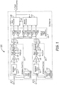
- FIG. 1 is a block diagram of an on-board receiver 100 in an ILS that includes wideband front ends 102 and 104 and a bank of digital down-converters 106 according to one embodiment of the present invention.
- Receiver 100 includes both analog circuitry (including mixed signal circuitry) and digital circuitry. Receiver 100 is designed to enable real-time detection of faults in both the analog circuitry and the digital circuitry that makes up receiver 100.
- the analog circuitry includes the wideband front ends 102 and 104 as well as analog-to-digital (A/D) converters 116 and 118.
- the digital circuitry includes the bank of digital down-converters 106, the main processor 120 and the monitor processor 122.
- Receiver 100 receives guidance signals from ground-based transmitters of the ILS and processes the signals to provide input to a flight control system on-board an aircraft (see Fig. 3 ). Receiver 100 processes the received guidance signals, along with test signals, to detect any faults in the operation of receiver 100. The test signals are injected during the flight of the associated aircraft, including during the landing phase. Further, the wideband feature of front ends 102 and 104 enable receipt of the assigned guidance signal without requiring tuning to a particular guidance signal and enables contemporaneous receipt of the test signal. This enables receiver 100 to simultaneously provide input to the flight control system and also detect faults in the circuitry by processing a known test signal in a real time.
- Wideband front end 102 is coupled to antenna 108.
- wideband front end 102 is tuned to receive the localizer (horizontal guidance) channels in the VHF navigation band (e.g., 108-112 MHz).
- First test signal generator 112 is coupled to inject a first test signal into wideband front end 102.
- the first test signal is injected while the aircraft is in flight, including during landing.
- the first test signal is injected at an edge of the band, e.g., at 108 or 112 MHz.
- the test signal is injected at other appropriate frequencies in the bandwidth of wideband front end 102.
- the output of wideband front end 102 is coupled to A/D converter 116.
- A/D converter 116 converts the wideband output signal, e.g., the VHF navigation band, into digitized spectrum.
- the digitized spectrum includes the specific localizer signal assigned to the aircraft for the receiver 100 as well as the test signal from first test signal generator 112.
- Wideband front end 104 is coupled to antenna 110.
- wideband front end 104 is tuned to receive the glide slope (vertical guidance) channels in the UHF navigation band (e.g., 328-336 MHz).
- Second test signal generator 114 is coupled to inject a second test signal into wideband front end 104.
- the second test signal is injected during the flight including during the landing phase.
- the second test signal is injected at an edge of the band, e.g., at 328 or 336 MHz.
- the test signal is injected at other appropriate frequencies in the bandwidth of wideband front end 104.
- the output of wideband front end 104 is coupled to A/D converter 118.
- A/D converter 118 converts the wideband output signal, e.g., the UHF navigation band, into digitized spectrum.
- the digitized spectrum includes the specific glide slope signal assigned to the aircraft for the receiver 100 as well as the test signal from second test signal generator 114.
- Figure 1 illustrates one embodiment of wideband front end.
- wideband front end 102 in one embodiment, includes bandpass filter 124 that is coupled to the output of antenna 108.
- Bandpass filter is tuned to the appropriate frequency band. In one example, this frequency band is the VHF navigation band.
- Bandpass filter 124 is coupled to Low Noise Amplifier (LNA) 126.
- LNA 126 is coupled to mixer 128 that down-converts the output of LNA 126 to an intermediate frequency using a fixed local oscillator.
- the output of mixer 128 is provided to bandpass filter 130.
- the output of bandpass filter 130 is coupled to A/D converter 116.
- LNA Low Noise Amplifier
- A/D converter 116 digitizes the down-converted frequency band, e.g., the VHF frequency band that has been down-converted to an intermediate frequency.
- This down-converted, digitized frequency band includes the channels that are used to carry the localizer signal as well as the first test signal.
- Wideband front end 104 similarly includes serially connected bandpass filter 132, low noise amplifier 134, mixer 136 and bandpass filter 138. These components of wideband front end 104 are tuned to process a second frequency band, such as the UHF navigation band, to provide a down-converted, digitized frequency band that includes the channels that are used to carry the glide slope signal as well as the second test signal.
- Bank of digital down-converters 106 extracts signals from the digitized spectrum output by A/D converters 116 and 118 to be used by the receiver 100 for fault detection and flight control.
- DDC digital down-converters
- DDC 140 and DDC 142 each down-convert a selected channel containing the desired first guidance signal, such as a localizer signal, and reject all other signals present in the digitized spectrum output from A/D converter 116.
- DDC 144 and DDC 145 each down-convert a selected channel containing the desired second guidance signal, such as a glide slope signal, and reject all other signals present in the digitized output of A/D converter 118.
- the output of DDC 140 and 144 are used by main processor 120 to generate lateral and vertical guidance for the flight control system. Similar calculations are made by monitor processor 122 based on the outputs of DDC 142 and DDC 145. Monitor processor 122 compares the lateral and vertical guidance output of main processor 120 with its own calculation and declares a fault when the calculations of either lateral or vertical guidance do not match. This fault is communicated from monitor processor 122 to main processor 120. Main processor 120 flags the non-matching lateral or vertical guidance output as invalid.
- bank of digital down-converters 106 also includes DDCs that are tuned to down-convert signals used to identify faults in the analog circuitry.
- bank of digital down-converters 106 includes DDC 148 and DDC 150.
- DDC 148 is tuned to down-convert the first test signal and to reject all other signals from the digitized spectrum output from A/D converter 116.
- DDC 150 is tuned to down-convert the second test signal and to reject all other signals from the digitized spectrum output by A/D 118.
- Monitor processor 122 compares the first and second test signals from DDC 148 and DDC 150 with the expected results from the respective test signals.
- monitor processor 122 detects faults in wideband front end 102 and/or wideband front end 104. These faults are communicated by monitor processor 122 to main processor 120. Main processor 120 flags the guidance signal associated with the faulty wideband front end as invalid.
- Figure 1 has been shown with first and second wideband front ends, it is understood that any appropriate number of wideband front ends could be used in a particular embodiment based on the bands used to carry the expected and test signals. For example, a single wideband front end could be used if the expected signal(s) are carried within a bandwidth associated with the wideband front end.
- Figure 2 is a flow chart of one embodiment of a method 200 for detecting faults in an on-board receiver of an ILS according to one embodiment of the present invention.
- the method uses injected test signals along with redundant digital processing of guidance signals to detect faults in both the analog circuitry and digital circuitry of the receiver.
- the method receives signals in one or more navigation bands from an ILS. For example, the method receives signals in VHF and UHF navigation bands that include both glide slope and localizer signals from the ILS.
- the method further injects test signals that are used to test analog circuitry of the receiver for faults.
- a test signal is injected in each navigation band while the aircraft is in flight, including during the landing phase.
- the test signals are injected at a frequency adjacent to a band that contains an expected signal, e.g., adjacent to a respective navigation band.
- the signals in the navigation band and the test signals are combined (block 205) and, at block 206, the method converts the received navigation bands to digitized spectrum.
- the digitized spectrum includes each of the navigation bands along with the injected test signals.
- the method 200 processes the digitized spectrum to detect faults in the analog and digital circuitry of the receiver.
- the method digitally down-converts and extracts the test signals from among all the signals present in the digitized spectrum.
- the method monitors the down-converted test signals for failure in the analog circuitry and/or mixed signal A/D converters. For example, the method compares the received test signals with expected values and declares a fault based on the comparison.
- the method down-converts and extracts the desired, i.e. selected, guidance signals from among all the signals present in the navigation band such as the glide slope and localizer signals, at block 208.
- the guidance signals are then processed to compute and output the lateral and vertical deviations from the landing path at block 209.
- the method further monitors (210) the computed lateral and vertical deviations for faults in the digital circuitry.
- the down conversion, extraction of the desired guidance signals, and lateral and vertical deviation calculations are performed in parallel using redundant and maybe even dissimilar digital processing circuitry. Disagreement between the redundant lateral or vertical deviation calculations indicates a fault in the digital circuitry.
- FIG 3 is a perspective diagram of an ILS 300 with real-time detection of faults of on-board receiver 308 according to one embodiment of the present invention.
- ILS 300 shows transmission of localizer and glide slope signals from ground station antenna 302 and 304, respectively.
- Aircraft 305 includes on-board receiver 308.
- This receiver in one embodiment, is constructed as described above with respect to Figure 1 and functions as described with respect to Figures 1 or 2 .
- On-board receiver 308 has a wideband front end that is coupled to first and second antenna 310 and 312 to receive guidance signals in two navigation bands. For example, antenna 310 receives a localizer signal in the VHF navigation band and antenna 312 receives a glide slope signal in the UHF navigation band.
- On-board receiver 308 uses these signals, along with test signals injected at the edge of the navigation bands, to provide fault detection for the analog and digital circuitry of on-board receiver 308.
- the analog and some digital circuitry are tested for faults based on the test signals. Further, the digital circuitry is tested for faults based on the received guidance signals from the navigation bands.
- the receiver 308 provides real-time fault detection by digitizing each navigation band and then digitally down-converting the test and guidance signals.
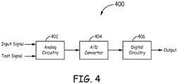
- FIG. 4 is a block diagram of another embodiment of the present invention.
- Electronic system 400 includes analog circuitry 402, analog to digital converter (A/D) 404 and digital circuitry 406.
- Electronic system 400 receives an input signal at analog circuitry 402 and provides an output signal at digital circuitry 406.
- Analog circuitry 402 also receives a test signal.
- the test signal is processed by the same circuitry that processes the input signal and is used to detect faults in electronic system 400.
- electronic system 400 is enabled to test for faults while processing live signals.
- analog circuitry 402 has a wide bandwidth that accepts a band that includes the input signal.
- the test signal is injected to analog circuitry 402.
- the injected test signal is injected at an edge of the band that contains the input signal.
- digital circuitry 400 detects faults in electronic system 400.
- Digital circuitry 406 detects faults in analog circuitry 402, A/D converter 404, and digital circuitry 406 using the injected test signal.
- Digital circuitry 406 compares the received test signal with an expected test signal and declares a fault based on a difference between the expected signal and the test signal.
Landscapes
- Engineering & Computer Science (AREA)
- Remote Sensing (AREA)
- Physics & Mathematics (AREA)
- General Physics & Mathematics (AREA)
- Computer Networks & Wireless Communication (AREA)
- Radar, Positioning & Navigation (AREA)
- Aviation & Aerospace Engineering (AREA)
- Monitoring And Testing Of Transmission In General (AREA)
- Analogue/Digital Conversion (AREA)
- Position Fixing By Use Of Radio Waves (AREA)
Claims (10)
- Empfänger (100) für ein Instrumentenlandesystem mit Echtzeitfehlererkennung, wobei der Empfänger umfasst:einen Testsignalgenerator (112);eine Antenne (108);ein Breitband-Frontend (108) mit einem Eingang, der mit der Antenne und dem Testsignalgenerator gekoppelt ist, wobei der Testsignalgenerator ein Testsignal an einer Flanke eines ausgewählten HF-Bandes einspeist, das ein erwartetes Führungssignal enthält,wobei das Testsignal verwendet wird, um Fehler im Instrumentenlandesystem zu identifizieren;einen Analog-Digital-A/D-Wandler (116), der mit einem Ausgang des Breitband-Frontends gekoppelt ist, das ein digitalisiertes Spektrum erzeugt, wobei das digitalisierte Spektrum das eingespeiste Testsignal und das ausgewählte HF-Band einschließlich des erwarteten Führungssignals enthält;eine Bank von digitalen Abwärtswandlern (106), die mit dem Ausgang des A/D-Wandlers gekoppelt sind;einen Hauptprozessor (120), der selektiv mit der Bank von digitalen Abwärtswandlern gekoppelt ist;einen Überwachungsprozessor (122), der selektiv mit der Bank von digitalen Abwärtswandlern gekoppelt ist;wobei die Bank von digitalen Abwärtswandlern selektiv das Testsignal und das erwartete Führungssignal aus dem digitalisierten Spektrum an die Haupt- und Überwachungsprozessoren liefert, um eine laterale und vertikale Führung für ein Flugsteuerungssystem bereitzustellen, und wobei der Überwachungsprozessor Fehler in der analogen und digitalen Schaltungsanordnung des Empfängers erkennt.
- Empfänger nach Anspruch 1 und ferner umfassend ein zweites Breitband-Frontend (104), das mit einer zweiten Antenne (110) und einem zweiten Testsignalgenerator (114) gekoppelt ist, wobei der zweite Testsignalgenerator ein zweites Testsignal an einer Flanke eines ausgewählten HF-Bandes einspeist, das ein zweites Führungssignal enthält, das in dem Instrumentenlandesystem verwendet wird.
- Empfänger nach Anspruch 2, wobei:das ausgewählte HF-Band des Breitband-Frontends ein UKW-Band umfasst, das ein Landekurssendersignal enthält; unddas zweite ausgewählte HF-Band des zweiten Breitband-Frontends ein UHF-Band umfasst, das ein Gleitwegsendersignal enthält.
- Empfänger nach Anspruch 3, wobei der Überwachungsprozessor die eingespeisten Testsignale verwendet, um Fehler in der analogen Schaltung zu erfassen, und der Überwachungs- und der Hauptprozessor das Landekurssendersignal und das Gleitwegsendersignal verwenden, um Fehler in der digitalen Schaltung zu erfassen.
- Empfänger nach Anspruch 1, wobei:die Antenne eine erste und eine zweite Antenne (108, 110) umfasst;das Breitband-Frontend umfasst:ein erstes Breitband-Frontend (102) für ein erstes Band, mit einem Eingang, der mit der ersten Antenne gekoppelt ist, wobei der Testsignalgenerator ein erstes Testsignal an einer Flanke des ersten Bandes einspeist;ein zweites Breitband-Frontend (104) für ein zweites Band, mit einem Eingang, der mit der zweiten Antenne gekoppelt ist, wobei der Testsignalgenerator ein zweites Testsignal an einer Flanke des zweiten Bandes einspeist;der A/D-Wandler umfasst:einen ersten Analog-Digital-Wandler (A/D) (116), der mit einem Ausgang des ersten Breitband-Frontends gekoppelt ist;einen zweiten Analog-Digital-Wandler (A/D) (118), der mit einem Ausgang des zweiten Breitband-Frontends verbunden ist;die Bank von digitalen Abwärtswandlern mit den Ausgängen des ersten und des zweiten A/D-Wandlers gekoppelt ist;wobei die Bank von digitalen Abwärtswandlern das erste und das zweite Testsignal an den Überwachungsprozessor liefert, um kontinuierlich auf Fehler im ersten und zweiten Breitband-Frontend zu überwachen;wobei die Bank von digitalen Abwärtswandlern auch einen ausgewählten Kanal vom ersten Breitband-Frontend zum Hauptprozessor und zum Überwachungsprozessor bereitstellt undeinen ausgewählten Kanal vom zweiten Breitband-Frontend zum Hauptprozessor und zum Überwachungsprozessor bereitstellt; undwobei der Hauptprozessor und der Überwachungsprozessor parallele, redundante Berechnungen der lateralen und vertikalen Abweichung durchführen und die Berechnungen vergleichen, um etwaige Fehler in der Bank von digitalen Abwärtswandlern, des Hauptprozessors und des Überwachungsprozessors zu erkennen.
- Empfänger nach Anspruch 5, wobei die Bank von digitalen Abwärtswandlern enthält:einen ersten digitalen Abwärtswandler (140), der zwischen dem ersten A/D-Wandler und dem Hauptprozessor gekoppelt ist, wobei der erste digitale Abwärtswandler einen ausgewählten Landekurssenderkanal in dem ersten Band, das dem Empfänger zugewiesen ist, abwärtswandelt;einen zweiten digitalen Abwärtsumwandler (144), der zwischen den zweiten A/D-Wandler und den Hauptprozessor gekoppelt ist, wobei der zweite digitale Abwärtsumwandler einen ausgewählten Gleitwegsenderkanal im zweiten Band, das dem Empfänger zugewiesen ist, umwandelt;einen dritten digitalen Abwärtswandler (142), der zwischen dem ersten A/D-Wandler und dem Überwachungsprozessor gekoppelt ist, wobei der dritte digitale Abwärtswandler den ausgewählten Landekurssenderkanal in dem ersten Band, das dem Empfänger zugewiesen ist, abwärtswandelt; undeinen vierten digitalen Abwärtswandler (145), der zwischen dem zweiten A/D-Wandler und dem Überwachungsprozessor gekoppelt ist, wobei der vierte digitale Abwärtswandler den ausgewählten Gleitwegsenderkanal in dem zweiten Band, das dem Empfänger zugewiesen ist, umwandelt.
- Verfahren zur Echtzeit-Fehlererkennung in einem Empfänger eines Instrumentenlandesystems, wobei das Verfahren umfasst:Empfangen eines Bandes von einem Sender des Instrumentenlandesystems, wobei das Band ein erwartetes Signal enthält;Einspeisen eines Testsignals mit einer Frequenz neben dem Band, das das erwartete Signal enthält;Umwandeln des Testsignals und des Bandes, das das erwartete Signal enthält, in ein digitalisiertes Spektrum, wobei das digitalisierte Spektrum das Testsignal enthält und das Band, das das erwartete Signal enthält;selektives Abwärtsumwandeln des erwarteten Signals und des Testsignals aus dem digitalisierten Spektrum;Überwachen des abwärtgewandelten Testsignals, um Fehler in der analogen und gemischten Signalschaltung des Empfängers zu identifizieren;Berechnen der vertikalen und lateralen Abweichung auf der Grundlage der abwärtsgewandelten erwarteten Signale; undÜberwachen der berechneten vertikalen und lateralen Abweichungen;Identifizieren von Fehlern in der digitalen Schaltung des Empfängers; undBereitstellen einer lateralen und vertikalen Führung für ein Flugzeugsystem auf der Grundlage des abwärtsgewandelten erwarteten Signals.
- Verfahren nach Anspruch 7, wobei das Empfangen des Führungssignals von einem Sender eines Instrumentenlandesystems das Empfangen von Landekurssender- und Gleitwegsendersignalen umfasst.
- Verfahren nach Anspruch 8, wobei das Einspeisen des Testsignals das Einspeisen eines ersten Testsignals neben einem UKW-Band, das für das Landekurssendersignal verwendet wird, und das Einspeisen eines zweiten Testsignals neben einem UHF-Band, das für das Gleitwegsendersignal verwendet wird, umfasst.
- Verfahren nach Anspruch 7, wobei das Berechnen vertikaler und lateraler Abweichungen das separate Berechnen vertikaler und lateraler Abweichungen in parallelen, redundanten Pfaden umfasst.
Applications Claiming Priority (1)
| Application Number | Priority Date | Filing Date | Title |
|---|---|---|---|
| US13/941,130 US9159242B2 (en) | 2013-07-12 | 2013-07-12 | Real-time fault detection in an instrument landing system |
Publications (3)
| Publication Number | Publication Date |
|---|---|
| EP2840411A2 EP2840411A2 (de) | 2015-02-25 |
| EP2840411A3 EP2840411A3 (de) | 2015-04-08 |
| EP2840411B1 true EP2840411B1 (de) | 2020-09-23 |
Family
ID=51167597
Family Applications (1)
| Application Number | Title | Priority Date | Filing Date |
|---|---|---|---|
| EP14173998.7A Active EP2840411B1 (de) | 2013-07-12 | 2014-06-25 | Echtzeit-Fehlererkennung bei einem Instrumentenlandesystem |
Country Status (3)
| Country | Link |
|---|---|
| US (1) | US9159242B2 (de) |
| EP (1) | EP2840411B1 (de) |
| CN (1) | CN104283622A (de) |
Families Citing this family (7)
| Publication number | Priority date | Publication date | Assignee | Title |
|---|---|---|---|---|
| KR101715336B1 (ko) * | 2014-10-31 | 2017-03-10 | 한국항공우주연구원 | 항공기 착륙을 위한 통합 착륙 수신 장치 및 그 제어 방법 |
| US9450598B2 (en) * | 2015-01-26 | 2016-09-20 | Guzik Technical Enterprises | Two-stage digital down-conversion of RF pulses |
| CN105466453B (zh) * | 2015-11-19 | 2018-04-24 | 中国民用航空总局第二研究所 | 一种导航设备在线监测系统及方法 |
| US20190215139A1 (en) * | 2018-01-08 | 2019-07-11 | Maxlinear, Inc. | Digital CW Cancellation for High QAM For Point-to-Point FDD Systems |
| US12126427B2 (en) * | 2020-07-20 | 2024-10-22 | The Board Of Regents Of The University Of Oklahoma | VHF-omnidirectional range/instrument landing system receiver and methods of use |
| CN114545907B (zh) * | 2022-03-15 | 2023-12-19 | 中南大学 | 一种基于滤波器的飞行控制系统的故障检测方法 |
| CN117872259B (zh) * | 2024-03-13 | 2024-06-11 | 天津七六四通信导航技术有限公司 | 仪表着陆系统中下滑监测信号的处理方法及系统 |
Citations (1)
| Publication number | Priority date | Publication date | Assignee | Title |
|---|---|---|---|---|
| EP2253967A1 (de) * | 2009-05-14 | 2010-11-24 | Honeywell International Inc. | System und Verfahren zur Verbesserung der Sensibilität von flachen Informationsbandbreitenempfängern |
Family Cites Families (12)
| Publication number | Priority date | Publication date | Assignee | Title |
|---|---|---|---|---|
| US3820115A (en) | 1971-09-24 | 1974-06-25 | N Stone | Navigational receiver failure warning system |
| US3750176A (en) | 1971-10-05 | 1973-07-31 | Bendix Corp | Integrity monitor for ils receiver with automatic change of monitor threshold sensitivity |
| US4390949A (en) * | 1981-05-26 | 1983-06-28 | Rockwell International Corporation | Electronic system and method for self-calibration of instrument landing systems |
| US4916612A (en) | 1987-11-02 | 1990-04-10 | The Boeing Company | Dual channel signal selection and fault detection system |
| DE3885092T2 (de) | 1988-04-21 | 1994-05-19 | Hazeltine Corp | Automatische Überprüfungsschaltung in Echtzeit für einen Fehlermonitor in einem Mikrowellenlandesystem. |
| US5254998A (en) * | 1992-11-02 | 1993-10-19 | Allied-Signal Inc. | Executive monitor for microwave landing system |
| CA2120077A1 (en) * | 1993-06-17 | 1994-12-18 | Louis Labreche | System and method for modulating a carrier frequency |
| US5909193A (en) * | 1995-08-31 | 1999-06-01 | Northrop Grumman Corporation | Digitally programmable radio modules for navigation systems |
| US5712628A (en) * | 1995-08-31 | 1998-01-27 | Northrop Grumman Corporation | Digitally programmable radio modules for transponder systems |
| US5859878A (en) * | 1995-08-31 | 1999-01-12 | Northrop Grumman Corporation | Common receive module for a programmable digital radio |
| FR2920063B1 (fr) | 2007-08-17 | 2011-04-29 | Thales Sa | Recepteur de signaux haute frequence recevant simultanement plusieurs tels signaux |
| US8711993B2 (en) | 2010-12-10 | 2014-04-29 | Honeywell International Inc. | Wideband multi-channel receiver with fixed-frequency notch filter for interference rejection |
-
2013
- 2013-07-12 US US13/941,130 patent/US9159242B2/en active Active
-
2014
- 2014-06-25 EP EP14173998.7A patent/EP2840411B1/de active Active
- 2014-07-11 CN CN201410331799.2A patent/CN104283622A/zh active Pending
Patent Citations (1)
| Publication number | Priority date | Publication date | Assignee | Title |
|---|---|---|---|---|
| EP2253967A1 (de) * | 2009-05-14 | 2010-11-24 | Honeywell International Inc. | System und Verfahren zur Verbesserung der Sensibilität von flachen Informationsbandbreitenempfängern |
Also Published As
| Publication number | Publication date |
|---|---|
| US20150019051A1 (en) | 2015-01-15 |
| US9159242B2 (en) | 2015-10-13 |
| CN104283622A (zh) | 2015-01-14 |
| EP2840411A2 (de) | 2015-02-25 |
| EP2840411A3 (de) | 2015-04-08 |
Similar Documents
| Publication | Publication Date | Title |
|---|---|---|
| EP2840411B1 (de) | Echtzeit-Fehlererkennung bei einem Instrumentenlandesystem | |
| CN107110975B (zh) | 用于旋翼飞行器的驾驶传感器的冗余设备 | |
| US10859708B2 (en) | Satellite positioning system receiver capable of detecting failure in RF receiver unit including receiving antenna | |
| US8144054B2 (en) | Satellite receiver and method for navigation using merged satellite system signals | |
| CN104134373B (zh) | 用于ads-b验证和导航的使用到达角测量的装置、系统和方法 | |
| US6667713B2 (en) | Self-monitoring satellite system | |
| Novák et al. | Measuring and testing the instrument landing system at the airport Zilina | |
| US7383124B1 (en) | ADS-B broadcast monitoring system and method | |
| CA2699617A1 (en) | Multifrequency receiver intended for satellite location | |
| EP3035557B1 (de) | Sektorierte antennen zum verbesserten luftgetragenen empfang von überwachungssignalen | |
| US20150325129A1 (en) | Method for geo-locating raw data exchanged during an air/ground transmission and a corresponding geo-location device | |
| CN110582707A (zh) | 用于定位系统的无线电接收器 | |
| US6111543A (en) | Method and device for analysing radio navigation signals | |
| US9726757B2 (en) | Radar device and process therefor | |
| US20110216859A1 (en) | High-Frequency Signal Receiver Simultaneously Receiving Several Such Signals | |
| Nguyen et al. | In-flight performance analysis of direct RF sampling architecture applied to VHF band avionics | |
| US20190208485A1 (en) | Aircraft time synchronization system | |
| US6414632B1 (en) | Monitoring of the phase angle of course and clearance signals in an instrument landing system | |
| CN106597482A (zh) | 一种具有防单频段射频欺骗的可信定位跟踪器 | |
| CN120164355B (zh) | 飞机引导降落基于信号触发的自动选择提示方法及系统 | |
| Hu et al. | Multiple reference consistency check algorithm in GBAS based on S-values auxiliary | |
| US9130639B2 (en) | Frequency resolver | |
| Lo et al. | Flight Test of a Pseudo Ranging Signal Compatible with Existing Distance Measurement Equipment (DME) Ground Stations | |
| JP2017053633A (ja) | レーダ受信装置 | |
| KR20250146627A (ko) | 자동 방향 탐지를 위한 시스템 및 방법 |
Legal Events
| Date | Code | Title | Description |
|---|---|---|---|
| PUAI | Public reference made under article 153(3) epc to a published international application that has entered the european phase |
Free format text: ORIGINAL CODE: 0009012 |
|
| 17P | Request for examination filed |
Effective date: 20140625 |
|
| AK | Designated contracting states |
Kind code of ref document: A2 Designated state(s): AL AT BE BG CH CY CZ DE DK EE ES FI FR GB GR HR HU IE IS IT LI LT LU LV MC MK MT NL NO PL PT RO RS SE SI SK SM TR |
|
| AX | Request for extension of the european patent |
Extension state: BA ME |
|
| PUAL | Search report despatched |
Free format text: ORIGINAL CODE: 0009013 |
|
| AK | Designated contracting states |
Kind code of ref document: A3 Designated state(s): AL AT BE BG CH CY CZ DE DK EE ES FI FR GB GR HR HU IE IS IT LI LT LU LV MC MK MT NL NO PL PT RO RS SE SI SK SM TR |
|
| AX | Request for extension of the european patent |
Extension state: BA ME |
|
| RIC1 | Information provided on ipc code assigned before grant |
Ipc: G08G 5/02 20060101ALI20150227BHEP Ipc: G01S 1/02 20100101AFI20150227BHEP Ipc: G01S 1/14 20060101ALI20150227BHEP |
|
| RAP1 | Party data changed (applicant data changed or rights of an application transferred) |
Owner name: HONEYWELL INTERNATIONAL INC. |
|
| STAA | Information on the status of an ep patent application or granted ep patent |
Free format text: STATUS: EXAMINATION IS IN PROGRESS |
|
| 17Q | First examination report despatched |
Effective date: 20180315 |
|
| GRAP | Despatch of communication of intention to grant a patent |
Free format text: ORIGINAL CODE: EPIDOSNIGR1 |
|
| STAA | Information on the status of an ep patent application or granted ep patent |
Free format text: STATUS: GRANT OF PATENT IS INTENDED |
|
| INTG | Intention to grant announced |
Effective date: 20200518 |
|
| RIN1 | Information on inventor provided before grant (corrected) |
Inventor name: MALAGA, ALFONSO Inventor name: DEVENSKY, WALTER |
|
| GRAS | Grant fee paid |
Free format text: ORIGINAL CODE: EPIDOSNIGR3 |
|
| GRAA | (expected) grant |
Free format text: ORIGINAL CODE: 0009210 |
|
| STAA | Information on the status of an ep patent application or granted ep patent |
Free format text: STATUS: THE PATENT HAS BEEN GRANTED |
|
| AK | Designated contracting states |
Kind code of ref document: B1 Designated state(s): AL AT BE BG CH CY CZ DE DK EE ES FI FR GB GR HR HU IE IS IT LI LT LU LV MC MK MT NL NO PL PT RO RS SE SI SK SM TR |
|
| REG | Reference to a national code |
Ref country code: GB Ref legal event code: FG4D |
|
| REG | Reference to a national code |
Ref country code: CH Ref legal event code: EP |
|
| REG | Reference to a national code |
Ref country code: IE Ref legal event code: FG4D |
|
| REG | Reference to a national code |
Ref country code: DE Ref legal event code: R096 Ref document number: 602014070416 Country of ref document: DE Ref country code: AT Ref legal event code: REF Ref document number: 1316944 Country of ref document: AT Kind code of ref document: T Effective date: 20201015 |
|
| PG25 | Lapsed in a contracting state [announced via postgrant information from national office to epo] |
Ref country code: GR Free format text: LAPSE BECAUSE OF FAILURE TO SUBMIT A TRANSLATION OF THE DESCRIPTION OR TO PAY THE FEE WITHIN THE PRESCRIBED TIME-LIMIT Effective date: 20201224 Ref country code: NO Free format text: LAPSE BECAUSE OF FAILURE TO SUBMIT A TRANSLATION OF THE DESCRIPTION OR TO PAY THE FEE WITHIN THE PRESCRIBED TIME-LIMIT Effective date: 20201223 Ref country code: HR Free format text: LAPSE BECAUSE OF FAILURE TO SUBMIT A TRANSLATION OF THE DESCRIPTION OR TO PAY THE FEE WITHIN THE PRESCRIBED TIME-LIMIT Effective date: 20200923 Ref country code: SE Free format text: LAPSE BECAUSE OF FAILURE TO SUBMIT A TRANSLATION OF THE DESCRIPTION OR TO PAY THE FEE WITHIN THE PRESCRIBED TIME-LIMIT Effective date: 20200923 Ref country code: FI Free format text: LAPSE BECAUSE OF FAILURE TO SUBMIT A TRANSLATION OF THE DESCRIPTION OR TO PAY THE FEE WITHIN THE PRESCRIBED TIME-LIMIT Effective date: 20200923 Ref country code: BG Free format text: LAPSE BECAUSE OF FAILURE TO SUBMIT A TRANSLATION OF THE DESCRIPTION OR TO PAY THE FEE WITHIN THE PRESCRIBED TIME-LIMIT Effective date: 20201223 |
|
| REG | Reference to a national code |
Ref country code: AT Ref legal event code: MK05 Ref document number: 1316944 Country of ref document: AT Kind code of ref document: T Effective date: 20200923 |
|
| PG25 | Lapsed in a contracting state [announced via postgrant information from national office to epo] |
Ref country code: LV Free format text: LAPSE BECAUSE OF FAILURE TO SUBMIT A TRANSLATION OF THE DESCRIPTION OR TO PAY THE FEE WITHIN THE PRESCRIBED TIME-LIMIT Effective date: 20200923 Ref country code: RS Free format text: LAPSE BECAUSE OF FAILURE TO SUBMIT A TRANSLATION OF THE DESCRIPTION OR TO PAY THE FEE WITHIN THE PRESCRIBED TIME-LIMIT Effective date: 20200923 |
|
| REG | Reference to a national code |
Ref country code: NL Ref legal event code: MP Effective date: 20200923 |
|
| REG | Reference to a national code |
Ref country code: LT Ref legal event code: MG4D |
|
| PG25 | Lapsed in a contracting state [announced via postgrant information from national office to epo] |
Ref country code: CZ Free format text: LAPSE BECAUSE OF FAILURE TO SUBMIT A TRANSLATION OF THE DESCRIPTION OR TO PAY THE FEE WITHIN THE PRESCRIBED TIME-LIMIT Effective date: 20200923 Ref country code: EE Free format text: LAPSE BECAUSE OF FAILURE TO SUBMIT A TRANSLATION OF THE DESCRIPTION OR TO PAY THE FEE WITHIN THE PRESCRIBED TIME-LIMIT Effective date: 20200923 Ref country code: LT Free format text: LAPSE BECAUSE OF FAILURE TO SUBMIT A TRANSLATION OF THE DESCRIPTION OR TO PAY THE FEE WITHIN THE PRESCRIBED TIME-LIMIT Effective date: 20200923 Ref country code: NL Free format text: LAPSE BECAUSE OF FAILURE TO SUBMIT A TRANSLATION OF THE DESCRIPTION OR TO PAY THE FEE WITHIN THE PRESCRIBED TIME-LIMIT Effective date: 20200923 Ref country code: PT Free format text: LAPSE BECAUSE OF FAILURE TO SUBMIT A TRANSLATION OF THE DESCRIPTION OR TO PAY THE FEE WITHIN THE PRESCRIBED TIME-LIMIT Effective date: 20210125 Ref country code: SM Free format text: LAPSE BECAUSE OF FAILURE TO SUBMIT A TRANSLATION OF THE DESCRIPTION OR TO PAY THE FEE WITHIN THE PRESCRIBED TIME-LIMIT Effective date: 20200923 Ref country code: RO Free format text: LAPSE BECAUSE OF FAILURE TO SUBMIT A TRANSLATION OF THE DESCRIPTION OR TO PAY THE FEE WITHIN THE PRESCRIBED TIME-LIMIT Effective date: 20200923 |
|
| PG25 | Lapsed in a contracting state [announced via postgrant information from national office to epo] |
Ref country code: AL Free format text: LAPSE BECAUSE OF FAILURE TO SUBMIT A TRANSLATION OF THE DESCRIPTION OR TO PAY THE FEE WITHIN THE PRESCRIBED TIME-LIMIT Effective date: 20200923 Ref country code: AT Free format text: LAPSE BECAUSE OF FAILURE TO SUBMIT A TRANSLATION OF THE DESCRIPTION OR TO PAY THE FEE WITHIN THE PRESCRIBED TIME-LIMIT Effective date: 20200923 Ref country code: ES Free format text: LAPSE BECAUSE OF FAILURE TO SUBMIT A TRANSLATION OF THE DESCRIPTION OR TO PAY THE FEE WITHIN THE PRESCRIBED TIME-LIMIT Effective date: 20200923 Ref country code: IS Free format text: LAPSE BECAUSE OF FAILURE TO SUBMIT A TRANSLATION OF THE DESCRIPTION OR TO PAY THE FEE WITHIN THE PRESCRIBED TIME-LIMIT Effective date: 20210123 Ref country code: PL Free format text: LAPSE BECAUSE OF FAILURE TO SUBMIT A TRANSLATION OF THE DESCRIPTION OR TO PAY THE FEE WITHIN THE PRESCRIBED TIME-LIMIT Effective date: 20200923 |
|
| REG | Reference to a national code |
Ref country code: DE Ref legal event code: R097 Ref document number: 602014070416 Country of ref document: DE |
|
| PG25 | Lapsed in a contracting state [announced via postgrant information from national office to epo] |
Ref country code: SK Free format text: LAPSE BECAUSE OF FAILURE TO SUBMIT A TRANSLATION OF THE DESCRIPTION OR TO PAY THE FEE WITHIN THE PRESCRIBED TIME-LIMIT Effective date: 20200923 |
|
| PLBE | No opposition filed within time limit |
Free format text: ORIGINAL CODE: 0009261 |
|
| STAA | Information on the status of an ep patent application or granted ep patent |
Free format text: STATUS: NO OPPOSITION FILED WITHIN TIME LIMIT |
|
| PG25 | Lapsed in a contracting state [announced via postgrant information from national office to epo] |
Ref country code: SI Free format text: LAPSE BECAUSE OF FAILURE TO SUBMIT A TRANSLATION OF THE DESCRIPTION OR TO PAY THE FEE WITHIN THE PRESCRIBED TIME-LIMIT Effective date: 20200923 Ref country code: DK Free format text: LAPSE BECAUSE OF FAILURE TO SUBMIT A TRANSLATION OF THE DESCRIPTION OR TO PAY THE FEE WITHIN THE PRESCRIBED TIME-LIMIT Effective date: 20200923 |
|
| 26N | No opposition filed |
Effective date: 20210624 |
|
| PG25 | Lapsed in a contracting state [announced via postgrant information from national office to epo] |
Ref country code: IT Free format text: LAPSE BECAUSE OF FAILURE TO SUBMIT A TRANSLATION OF THE DESCRIPTION OR TO PAY THE FEE WITHIN THE PRESCRIBED TIME-LIMIT Effective date: 20200923 |
|
| PG25 | Lapsed in a contracting state [announced via postgrant information from national office to epo] |
Ref country code: MC Free format text: LAPSE BECAUSE OF FAILURE TO SUBMIT A TRANSLATION OF THE DESCRIPTION OR TO PAY THE FEE WITHIN THE PRESCRIBED TIME-LIMIT Effective date: 20200923 |
|
| REG | Reference to a national code |
Ref country code: CH Ref legal event code: PL |
|
| GBPC | Gb: european patent ceased through non-payment of renewal fee |
Effective date: 20210625 |
|
| REG | Reference to a national code |
Ref country code: BE Ref legal event code: MM Effective date: 20210630 |
|
| PG25 | Lapsed in a contracting state [announced via postgrant information from national office to epo] |
Ref country code: LU Free format text: LAPSE BECAUSE OF NON-PAYMENT OF DUE FEES Effective date: 20210625 |
|
| PG25 | Lapsed in a contracting state [announced via postgrant information from national office to epo] |
Ref country code: LI Free format text: LAPSE BECAUSE OF NON-PAYMENT OF DUE FEES Effective date: 20210630 Ref country code: IE Free format text: LAPSE BECAUSE OF NON-PAYMENT OF DUE FEES Effective date: 20210625 Ref country code: GB Free format text: LAPSE BECAUSE OF NON-PAYMENT OF DUE FEES Effective date: 20210625 Ref country code: CH Free format text: LAPSE BECAUSE OF NON-PAYMENT OF DUE FEES Effective date: 20210630 |
|
| PG25 | Lapsed in a contracting state [announced via postgrant information from national office to epo] |
Ref country code: BE Free format text: LAPSE BECAUSE OF NON-PAYMENT OF DUE FEES Effective date: 20210630 |
|
| PG25 | Lapsed in a contracting state [announced via postgrant information from national office to epo] |
Ref country code: HU Free format text: LAPSE BECAUSE OF FAILURE TO SUBMIT A TRANSLATION OF THE DESCRIPTION OR TO PAY THE FEE WITHIN THE PRESCRIBED TIME-LIMIT; INVALID AB INITIO Effective date: 20140625 |
|
| PG25 | Lapsed in a contracting state [announced via postgrant information from national office to epo] |
Ref country code: CY Free format text: LAPSE BECAUSE OF FAILURE TO SUBMIT A TRANSLATION OF THE DESCRIPTION OR TO PAY THE FEE WITHIN THE PRESCRIBED TIME-LIMIT Effective date: 20200923 |
|
| P01 | Opt-out of the competence of the unified patent court (upc) registered |
Effective date: 20230525 |
|
| PG25 | Lapsed in a contracting state [announced via postgrant information from national office to epo] |
Ref country code: MK Free format text: LAPSE BECAUSE OF FAILURE TO SUBMIT A TRANSLATION OF THE DESCRIPTION OR TO PAY THE FEE WITHIN THE PRESCRIBED TIME-LIMIT Effective date: 20200923 |
|
| PG25 | Lapsed in a contracting state [announced via postgrant information from national office to epo] |
Ref country code: TR Free format text: LAPSE BECAUSE OF FAILURE TO SUBMIT A TRANSLATION OF THE DESCRIPTION OR TO PAY THE FEE WITHIN THE PRESCRIBED TIME-LIMIT Effective date: 20200923 |
|
| PG25 | Lapsed in a contracting state [announced via postgrant information from national office to epo] |
Ref country code: MT Free format text: LAPSE BECAUSE OF FAILURE TO SUBMIT A TRANSLATION OF THE DESCRIPTION OR TO PAY THE FEE WITHIN THE PRESCRIBED TIME-LIMIT Effective date: 20200923 |
|
| PGFP | Annual fee paid to national office [announced via postgrant information from national office to epo] |
Ref country code: DE Payment date: 20250626 Year of fee payment: 12 |
|
| PGFP | Annual fee paid to national office [announced via postgrant information from national office to epo] |
Ref country code: FR Payment date: 20250624 Year of fee payment: 12 |