EP2840436A2 - Anzeigevorrichtung und Stützelement dafür - Google Patents
Anzeigevorrichtung und Stützelement dafür Download PDFInfo
- Publication number
- EP2840436A2 EP2840436A2 EP20140181094 EP14181094A EP2840436A2 EP 2840436 A2 EP2840436 A2 EP 2840436A2 EP 20140181094 EP20140181094 EP 20140181094 EP 14181094 A EP14181094 A EP 14181094A EP 2840436 A2 EP2840436 A2 EP 2840436A2
- Authority
- EP
- European Patent Office
- Prior art keywords
- support member
- backlight unit
- display device
- display panel
- light
- Prior art date
- Legal status (The legal status is an assumption and is not a legal conclusion. Google has not performed a legal analysis and makes no representation as to the accuracy of the status listed.)
- Withdrawn
Links
- 230000002093 peripheral effect Effects 0.000 claims abstract description 37
- 230000003287 optical effect Effects 0.000 claims description 41
- 230000001681 protective effect Effects 0.000 claims description 26
- 230000035515 penetration Effects 0.000 claims description 17
- 230000001105 regulatory effect Effects 0.000 claims description 16
- 229910052751 metal Inorganic materials 0.000 claims description 12
- 239000002184 metal Substances 0.000 claims description 12
- 239000000463 material Substances 0.000 claims description 11
- 239000004020 conductor Substances 0.000 claims description 3
- 230000003667 anti-reflective effect Effects 0.000 claims description 2
- 238000009413 insulation Methods 0.000 claims description 2
- 210000004027 cell Anatomy 0.000 description 156
- 239000004973 liquid crystal related substance Substances 0.000 description 60
- 210000002858 crystal cell Anatomy 0.000 description 49
- 239000011347 resin Substances 0.000 description 8
- 229920005989 resin Polymers 0.000 description 8
- 239000007769 metal material Substances 0.000 description 7
- 238000006748 scratching Methods 0.000 description 5
- 230000002393 scratching effect Effects 0.000 description 5
- 230000002265 prevention Effects 0.000 description 4
- 125000006850 spacer group Chemical group 0.000 description 4
- 230000000694 effects Effects 0.000 description 3
- 239000003566 sealing material Substances 0.000 description 3
- 238000005728 strengthening Methods 0.000 description 3
- 238000010586 diagram Methods 0.000 description 2
- 238000004519 manufacturing process Methods 0.000 description 2
- 239000003973 paint Substances 0.000 description 2
- 238000003825 pressing Methods 0.000 description 2
- 230000003014 reinforcing effect Effects 0.000 description 2
- 238000003466 welding Methods 0.000 description 2
- 229910000838 Al alloy Inorganic materials 0.000 description 1
- 229920000049 Carbon (fiber) Polymers 0.000 description 1
- RYGMFSIKBFXOCR-UHFFFAOYSA-N Copper Chemical compound [Cu] RYGMFSIKBFXOCR-UHFFFAOYSA-N 0.000 description 1
- 229910000881 Cu alloy Inorganic materials 0.000 description 1
- JOYRKODLDBILNP-UHFFFAOYSA-N Ethyl urethane Chemical compound CCOC(N)=O JOYRKODLDBILNP-UHFFFAOYSA-N 0.000 description 1
- 229910000831 Steel Inorganic materials 0.000 description 1
- 229910052782 aluminium Inorganic materials 0.000 description 1
- XAGFODPZIPBFFR-UHFFFAOYSA-N aluminium Chemical compound [Al] XAGFODPZIPBFFR-UHFFFAOYSA-N 0.000 description 1
- 230000005540 biological transmission Effects 0.000 description 1
- 239000004917 carbon fiber Substances 0.000 description 1
- 239000000919 ceramic Substances 0.000 description 1
- ZCDOYSPFYFSLEW-UHFFFAOYSA-N chromate(2-) Chemical compound [O-][Cr]([O-])(=O)=O ZCDOYSPFYFSLEW-UHFFFAOYSA-N 0.000 description 1
- 239000011248 coating agent Substances 0.000 description 1
- 238000000576 coating method Methods 0.000 description 1
- 230000008602 contraction Effects 0.000 description 1
- 239000010949 copper Substances 0.000 description 1
- 229910052802 copper Inorganic materials 0.000 description 1
- 238000002788 crimping Methods 0.000 description 1
- 230000008021 deposition Effects 0.000 description 1
- 238000005516 engineering process Methods 0.000 description 1
- 238000005187 foaming Methods 0.000 description 1
- 230000001678 irradiating effect Effects 0.000 description 1
- VNWKTOKETHGBQD-UHFFFAOYSA-N methane Chemical compound C VNWKTOKETHGBQD-UHFFFAOYSA-N 0.000 description 1
- 238000000034 method Methods 0.000 description 1
- 230000000149 penetrating effect Effects 0.000 description 1
- 229920001296 polysiloxane Polymers 0.000 description 1
- 229920002635 polyurethane Polymers 0.000 description 1
- 239000004814 polyurethane Substances 0.000 description 1
- 230000005855 radiation Effects 0.000 description 1
- 239000010935 stainless steel Substances 0.000 description 1
- 229910001220 stainless steel Inorganic materials 0.000 description 1
- 239000010959 steel Substances 0.000 description 1
- 239000000126 substance Substances 0.000 description 1
- 239000000758 substrate Substances 0.000 description 1
Images




Classifications
-
- G—PHYSICS
- G02—OPTICS
- G02F—OPTICAL DEVICES OR ARRANGEMENTS FOR THE CONTROL OF LIGHT BY MODIFICATION OF THE OPTICAL PROPERTIES OF THE MEDIA OF THE ELEMENTS INVOLVED THEREIN; NON-LINEAR OPTICS; FREQUENCY-CHANGING OF LIGHT; OPTICAL LOGIC ELEMENTS; OPTICAL ANALOGUE/DIGITAL CONVERTERS
- G02F1/00—Devices or arrangements for the control of the intensity, colour, phase, polarisation or direction of light arriving from an independent light source, e.g. switching, gating or modulating; Non-linear optics
- G02F1/01—Devices or arrangements for the control of the intensity, colour, phase, polarisation or direction of light arriving from an independent light source, e.g. switching, gating or modulating; Non-linear optics for the control of the intensity, phase, polarisation or colour
- G02F1/13—Devices or arrangements for the control of the intensity, colour, phase, polarisation or direction of light arriving from an independent light source, e.g. switching, gating or modulating; Non-linear optics for the control of the intensity, phase, polarisation or colour based on liquid crystals, e.g. single liquid crystal display cells
- G02F1/133—Constructional arrangements; Operation of liquid crystal cells; Circuit arrangements
- G02F1/1333—Constructional arrangements; Manufacturing methods
- G02F1/133308—Support structures for LCD panels, e.g. frames or bezels
-
- G—PHYSICS
- G02—OPTICS
- G02F—OPTICAL DEVICES OR ARRANGEMENTS FOR THE CONTROL OF LIGHT BY MODIFICATION OF THE OPTICAL PROPERTIES OF THE MEDIA OF THE ELEMENTS INVOLVED THEREIN; NON-LINEAR OPTICS; FREQUENCY-CHANGING OF LIGHT; OPTICAL LOGIC ELEMENTS; OPTICAL ANALOGUE/DIGITAL CONVERTERS
- G02F1/00—Devices or arrangements for the control of the intensity, colour, phase, polarisation or direction of light arriving from an independent light source, e.g. switching, gating or modulating; Non-linear optics
- G02F1/01—Devices or arrangements for the control of the intensity, colour, phase, polarisation or direction of light arriving from an independent light source, e.g. switching, gating or modulating; Non-linear optics for the control of the intensity, phase, polarisation or colour
- G02F1/13—Devices or arrangements for the control of the intensity, colour, phase, polarisation or direction of light arriving from an independent light source, e.g. switching, gating or modulating; Non-linear optics for the control of the intensity, phase, polarisation or colour based on liquid crystals, e.g. single liquid crystal display cells
- G02F1/133—Constructional arrangements; Operation of liquid crystal cells; Circuit arrangements
- G02F1/1333—Constructional arrangements; Manufacturing methods
- G02F1/1335—Structural association of cells with optical devices, e.g. polarisers or reflectors
- G02F1/1336—Illuminating devices
-
- G—PHYSICS
- G02—OPTICS
- G02F—OPTICAL DEVICES OR ARRANGEMENTS FOR THE CONTROL OF LIGHT BY MODIFICATION OF THE OPTICAL PROPERTIES OF THE MEDIA OF THE ELEMENTS INVOLVED THEREIN; NON-LINEAR OPTICS; FREQUENCY-CHANGING OF LIGHT; OPTICAL LOGIC ELEMENTS; OPTICAL ANALOGUE/DIGITAL CONVERTERS
- G02F1/00—Devices or arrangements for the control of the intensity, colour, phase, polarisation or direction of light arriving from an independent light source, e.g. switching, gating or modulating; Non-linear optics
- G02F1/01—Devices or arrangements for the control of the intensity, colour, phase, polarisation or direction of light arriving from an independent light source, e.g. switching, gating or modulating; Non-linear optics for the control of the intensity, phase, polarisation or colour
- G02F1/13—Devices or arrangements for the control of the intensity, colour, phase, polarisation or direction of light arriving from an independent light source, e.g. switching, gating or modulating; Non-linear optics for the control of the intensity, phase, polarisation or colour based on liquid crystals, e.g. single liquid crystal display cells
- G02F1/133—Constructional arrangements; Operation of liquid crystal cells; Circuit arrangements
- G02F1/1333—Constructional arrangements; Manufacturing methods
- G02F1/133308—Support structures for LCD panels, e.g. frames or bezels
- G02F1/133317—Intermediate frames, e.g. between backlight housing and front frame
-
- G—PHYSICS
- G02—OPTICS
- G02F—OPTICAL DEVICES OR ARRANGEMENTS FOR THE CONTROL OF LIGHT BY MODIFICATION OF THE OPTICAL PROPERTIES OF THE MEDIA OF THE ELEMENTS INVOLVED THEREIN; NON-LINEAR OPTICS; FREQUENCY-CHANGING OF LIGHT; OPTICAL LOGIC ELEMENTS; OPTICAL ANALOGUE/DIGITAL CONVERTERS
- G02F1/00—Devices or arrangements for the control of the intensity, colour, phase, polarisation or direction of light arriving from an independent light source, e.g. switching, gating or modulating; Non-linear optics
- G02F1/01—Devices or arrangements for the control of the intensity, colour, phase, polarisation or direction of light arriving from an independent light source, e.g. switching, gating or modulating; Non-linear optics for the control of the intensity, phase, polarisation or colour
- G02F1/13—Devices or arrangements for the control of the intensity, colour, phase, polarisation or direction of light arriving from an independent light source, e.g. switching, gating or modulating; Non-linear optics for the control of the intensity, phase, polarisation or colour based on liquid crystals, e.g. single liquid crystal display cells
- G02F1/133—Constructional arrangements; Operation of liquid crystal cells; Circuit arrangements
- G02F1/1333—Constructional arrangements; Manufacturing methods
- G02F1/133308—Support structures for LCD panels, e.g. frames or bezels
- G02F1/133328—Segmented frames
-
- G—PHYSICS
- G02—OPTICS
- G02F—OPTICAL DEVICES OR ARRANGEMENTS FOR THE CONTROL OF LIGHT BY MODIFICATION OF THE OPTICAL PROPERTIES OF THE MEDIA OF THE ELEMENTS INVOLVED THEREIN; NON-LINEAR OPTICS; FREQUENCY-CHANGING OF LIGHT; OPTICAL LOGIC ELEMENTS; OPTICAL ANALOGUE/DIGITAL CONVERTERS
- G02F2201/00—Constructional arrangements not provided for in groups G02F1/00 - G02F7/00
- G02F2201/38—Anti-reflection arrangements
Definitions
- the present invention relates to a display device and a support member intended to support a display panel and a backlight unit of a display device.
- Conventional liquid crystal display devices are provided with a bezel made of metal that holds a peripheral edge portion of a liquid crystal panel from a front surface side for ensuring a strength of the liquid crystal panel.
- a display device is disclosed that ensures the strength of the liquid crystal panel while omitting the bezel made of metal in order to reduce a thickness and narrow a frame (see Patent Document 1).
- Patent Document 1 Japanese Unexamined Patent Application Publication No. 2009-134269
- the strength of the liquid crystal panel is ensured by reinforcing a cabinet made of resin that presses the peripheral edge portion of the liquid crystal panel from the front surface side.
- a sufficient strength is not ensured because a member made of metal is omitted, and it is difficult to reduce the thickness and narrow the frame because, in order to ensure sufficient strength in the display device, a thickness of a reinforcing portion has to be increased.
- One or more embodiments of the present invention provide a display device that can ensure a strength of a display panel while reducing a thickness and narrowing a frame, and a support structure of an optical member of the display device.
- a display device may comprise: a display panel configured to display an image on a screen on a front surface of the display panel; a backlight unit that covers a back surface side of the display panel and is configured to irradiate light toward the back surface side of the display panel; and a support member provided between the display panel and the backlight unit, wherein the support member may press at least a portion of a peripheral edge portion of the backlight unit from the front surface side, and the display device may further comprise at least one of a first protective member that is disposed on the support member in a position contacting the display panel and that protects a top surface of the display panel and a second protective member that is disposed on the support member in a position contacting the backlight unit and that protects a top surface of the backlight unit.
- the support member provided between the display panel and the backlight unit results in at least one portion of the peripheral edge portion of the display panel and the backlight unit having a predetermined strength.
- the display device may further comprise a back surface member disposed on a back surface side of the backlight unit and a frame-shaped member that presses a peripheral edge portion of the display panel from a front surface side of the display panel and is fixed to the back surface member.
- the support member provided between the display panel and the backlight unit may comprise a material having a predetermined rigidity, for example a rigidity substantially equal to the rigidity of a metal material.
- a predetermined rigidity for example a rigidity substantially equal to the rigidity of a metal material.
- At least one from among the first protective member and the second protective member may be disposed in positions, on the support member, contacting the display panel and the backlight unit. Because of this, the support member can be prevented from scratching the display panel and/or the backlight unit.
- a portion, for example an end portion of the support member toward a center of the screen may be subjected to an antireflection treatment that prevents light irradiated from the backlight unit from being reflected by the support member.
- the antireflection treatment that prevents the light irradiated from the backlight unit from being reflected by the support member may be applied to the end portion of the support member toward the center of the screen, the light irradiated from the backlight unit can be prevented from being reflected by a back surface side of the support member.
- the light can be prevented from being irradiated toward the back surface side of the display panel from an unintended direction and a quality of an image displayed on the display panel can be improved.
- the display device may comprise the second protective member.
- the antireflective treatment may be applied to the end portion of the support member toward the center of the screen by disposing the second protective member on the support member.
- the antireflection treatment may be applied to the end portion of the support member toward the center of the screen by disposing the second protective member on the support member, the support member can be prevented from scratching the backlight unit and the light irradiated from the backlight unit can be prevented from being reflected by the back surface side of the support member.
- the second protective member combines two functions of scratch prevention and reflection prevention, compared to a configuration that realizes each function with individual components, the number of components can be reduced. Because of this, for example, the structure of the display device can be simplified and the production cost of the display device can be reduced.
- the support member may comprise: a first support portion that presses the peripheral edge portion of the backlight unit from the front surface side; and a second support portion formed continuously along an outer peripheral edge of the first support portion toward a back surface side of the first support portion and disposed on a side of the backlight unit.
- the second support portion of the support member may be formed on a lateral side of the backlight unit in addition to the first support portion that presses a front surface side of the peripheral edge portion of the backlight unit, a strength of the backlight unit can be further ensured.
- the support member may comprise the first support portion and the second support portion and may be for example configured with an L-shaped cross section. In this manner, a strength thereof can be further increased compared to when, for example, the support member comprises the first support portion alone.
- the support member may comprise an electrically conductive material.
- the support member when the support member comprises an electrically conductive material, the support member may be provided with an insulation treatment that electrically insulates the support member from any electrical component disposed on a side of the support member.
- the support member may comprise a material having electrical conductivity and an insulating treatment may be applied between the support member and any electrical component disposed on a side of the support member, an electrical component can be prevented from being shorted by the support member when, for example, the electrical component contacts the support member due to an impact from the outside. By this, for example, a failure of electrical components due to shorting via the support member can be prevented.
- the support member may be thermally connected to one or more electrical components disposed on a side of the support member.
- the support member and any electrical component disposed on a side of the support member may be thermally connected, heat generated by the electrical component can be dissipated by the support member.
- the backlight unit may comprise: a light source; a light-guide plate configured to guide light from the light source to an inner portion of an enclosure of the display device and irradiate the light guided to the inner portion toward the back surface side of the display panel; and an optical sheet disposed on a front surface side of the light-guide plate.
- the light-guide plate and the optical sheet may each be disposed in a stacked configuration in which the entirety of an outer peripheral edge of the light-guide plate and the optical sheet overlaps at least one of the frame-shaped member and the support member when viewed from the front.
- the display device may further comprise: a position regulating portion that regulates movement of the light-guide plate, the optical sheet, the support member, and at least one of the frame-shaped member and the back surface member in a direction in which the light-guide plate, the optical sheet, the support member, and the at least one of the frame-shaped member and the back surface member intersect in a longitudinal direction.
- the display device comprises a position regulating portion
- relative positions of the light-guide plate and the optical sheet, which configure the backlight unit, and the support member, respectively, and at least one from among the frame-shaped member and the back surface member can be suppressed from shifting in the directions in which they intersect in the longitudinal direction. Because of this, for example, the stacked configuration can be easily maintained.
- the position regulating portion may comprise: a protruding portion formed on the back surface member or the frame-shaped member; a first penetration portion formed in an end portion of the light-guide plate and penetrated, in the stacked configuration, by the protruding portion at the end portion of the light-guide plate; a second penetration portion formed in the optical sheet and penetrated, in the stacked configuration, by the protruding portion along with the first penetration portion; and a third penetration portion formed in the support member and penetrated, in the stacked configuration, by the protruding portion along with the first penetration portion and the second penetration portion.
- the light-guide plate and the optical sheet of the backlight unit and the support member may be assembled in a configuration in which each is stacked in a predetermined position by being penetrated by the protruding portion formed on the back surface member or the frame-shaped member.
- the frame-shaped member and the back surface member may be fixed in predetermined positions, in this configuration, the light-guide plate, the optical sheet, the support member, the frame-shaped member, and the back surface member may be assembled by being stacked in a predetermined position.
- the position of the light-guide plate, the optical sheet, and the support member to the back surface member or the frame-shaped member can be easily determined.
- the display panel may have a quadrangle shape and the backlight unit may have a quadrangle shape corresponding to the quadrangle shape of the display panel.
- the support member may press four sides that are the peripheral edge portion of the backlight unit from the front surface side, and the support member may be formed with at least four incised clinch portions, in positions corresponding to each of the four sides of the backlight unit, for positioning the display panel.
- the support member is a member that may press the entirety of the four sides that are the peripheral edge portion of the backlight unit from the front. In this manner, the display panel and the backlight unit can be reliably strengthened.
- the incised clinch portions for position determining the display panel may be provided in the positions corresponding to each of the four sides. In this manner, the position of the display panel can be further easily determined.
- a display device as described in any of the above embodiments may comprise a support structure of an optical member.
- the support member may be a cell guide, which may for example be made of metal.
- the display panel can be strengthened while reducing the thickness and narrowing the frame.
- One or more embodiments of the present invention provide a support member intended to be provided between a display panel and a backlight unit of the display device according to any of the embodiments described above.
- the support member may be intended to press at least a portion of a peripheral edge portion of the backlight unit from the front surface side of the display device.
- the support member may comprise at least one of a first protective member intended to contact the display panel and protect a top surface of the display panel and a second protective member intended to contact the backlight unit and protect a top surface of the backlight unit.
- FIGS. 1 to 3 an overall configuration of a display device according to one or more embodiments of a first example will be described with reference to FIGS. 1 to 3 .
- an X-axis direction is illustrated as a lateral direction
- a Y-axis direction is illustrated as a vertical direction
- a Z-axis direction is illustrated as a longitudinal direction.
- an X-axis plus-direction side is defined as a right direction
- an X-axis minus-direction side is defined as a left direction
- a Y-axis plus-direction side is defined as an up direction
- a Y-axis minus-direction side is defined as a down direction
- a Z-axis plus-direction side is defined as a front direction
- a Z-axis minus-direction side is defined as a rear direction.
- FIG. 1 is a diagram illustrating an external appearance of the display device according to one or more embodiments of the first example.
- FIG. 2 is an exploded perspective view illustrating a display device according to one or more embodiments of the first example.
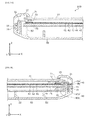
- FIG. 3A is an enlarged cross-sectional view of a left side of a display device cut along the line A-A in FIG. 1 .
- FIG. 3B is an enlarged cross-sectional view of a right side of the display device cut along the line A-A in FIG. 1 .
- a display device 100 is a liquid crystal television receiver comprising an enclosure 4.
- the enclosure 4 comprises a front cabinet 10 acting as a frame member and a rear frame 50 acting as a back surface member being combined with each other.
- the front cabinet 10 is configured in a frame shape and covers an outer peripheral portion of a liquid crystal cell 20 acting as a display panel that will be described below.
- the front cabinet 10 is fixed to the rear frame 50 while pressing a peripheral edge portion of the liquid crystal cell 20 from a front surface side via a cushion member 71 (see below).
- the front cabinet 10 is fixed to the rear frame 50 by fitting a hook portion 11, which is disposed on both a left and right end of the front cabinet 10 and extends rearward, into an opening portion 51 provided in the rear frame 50.
- the front cabinet 10 and the rear frame 50 may be fixed by a snap fit comprising the hook portion 11 and the opening portion 51.
- the front cabinet 10 is formed, for example, from resin.
- the rear frame 50 is disposed so as to cover a back surface side of the liquid crystal cell 20.
- the rear frame 50 is formed, for example, from resin.
- a rear cover 6 is installed to a central portion in an outer surface of the rear frame 50.
- a power source substrate or the like (not illustrated) for supplying power to the liquid crystal cell 20 and the like is disposed on an inner portion of the rear cover 6.
- a stand 12 for supporting the enclosure 4 from below is installed to a lower end portion of the rear cover 6. The stand 12 does not have to be installed to the rear cover 6.
- the rear cover 6 is formed, for example, from resin.
- the liquid crystal cell 20, a cell guide 30, and a backlight unit 40 are disposed on an inner portion of the enclosure 4.
- the cell guide 30 is an example of a support member.
- the liquid crystal cell 20 is an exemplary display panel whose outer shape may be a rectangular shape and is, for example, a liquid crystal display panel that can display an image at a resolution of 1920 ⁇ 1080.
- the liquid crystal cell 20 is a device that reproduces a desired color for each of a plurality of pixels by adjusting a transmission amount of light irradiated from the backlight unit 40 for a red, green, and blue color filter (not illustrated) provided to each of the plurality of pixels (for example, 1920 ⁇ 1080 pixels).
- the liquid crystal cell 20 can display a desired image on a screen on a front surface by reproducing the desired color in each of the plurality of pixels.
- the backlight unit 40 comprises a plurality of optical sheets 41 to 43, a light-guide plate 44, a reflective sheet 45, and a light-emitting diode (LED) bar 46 acting as a light source.
- LED light-emitting diode
- the plurality of optical sheets 41 to 43 is disposed on a front surface side of the light-guide plate 44.
- the plurality of optical sheets 41 to 43 includes, for example, a diffuser sheet that diffuses and makes uniform light irradiated from a front surface of the light-guide plate 44, a condenser sheet for efficiently irradiating a light made uniform to the liquid crystal cell 20, and the like.
- the light-guide plate 44 is a plate-shaped member corresponding to a shape of the liquid crystal cell 20 that guides a light from the light source to an inner portion and irradiates the light guided to the inner portion toward the back surface side of the liquid crystal cell 20.
- the light-guide plate 44 reflects the light guided from a side so that the light is irradiated toward the entirety of a back surface of the liquid crystal cell 20.
- the plurality of optical sheets 41 to 43 and the light-guide plate 44 are each disposed in a configuration (for example a stacked configuration) where the entirety of an outer peripheral edge thereof overlaps the cell guide 30.
- the LED bar 46 comprises a plurality of LEDs 46a being disposed on a main surface of an elongated plate-shaped member 46b by being lined up at predetermined intervals on one row along a lengthwise direction of the elongated plate-shaped member 46b.
- the LED bar 46 is disposed on a right side of the light-guide plate 44 and irradiates a light toward a left side, thus, for example, a right side surface of the light-guide plate 44.
- a heat sink 80 for disposing the LED bar 46 is disposed on a right side of the rear frame 50.
- the heat sink 80 is a member made of metal, whose cross-section is an L-shape.
- the heat sink 80 comprises a first heat sink 80a parallel to a Y-Z plane and a second heat sink 80b parallel to an X-Y plane.
- the first heat sink 80a is disposed on a right end of an inner portion of the rear frame 50.
- the second heat sink 80b is disposed so as to contact an upper end of a rib 52 that is formed on the rear frame 50 and extends frontward from a surface on a back surface side of the rear frame 50.
- the heat sink 80 is disposed on an end portion on a right-rear side in the inner portion of the rear frame 50.
- the elongated plate-shaped member 46b is disposed along the first heat sink 80a. In this manner, for example, heat generated by the LED bar 46 can be dissipated efficiently because the LED bar 46 is disposed so as to contact the heat sink 80.
- a spacer 81 for determining the position in the longitudinal direction for a right end of the light-guide plate 44 is provided to the left of the LED bar 46 in a state where the spacer 81 contacts a portion more rearward than the second heat sink 80b and the LED 46a of the elongated plate-shaped member 46b of the LED bar 46.
- the light-guide plate 44 is disposed in a position coinciding with an optical axis of the LED 46a of the LED bar 46 due to the spacer 81 via the reflective sheet 45.
- the cell guide 30 may be provided between the liquid crystal cell 20 and the backlight unit 40 and may be a member made of a metal such as steel, electrically chromate coated (SECC) and presses at least a portion of a peripheral edge portion of the backlight unit 40.
- SECC electrically chromate coated
- a cell guide is not limited to SECC and may comprise aluminum or an aluminum alloy, copper or a copper alloy, stainless steel, or the like.
- the cell guide 30 may be a member that presses four sides that are the peripheral edge portion of the backlight unit 40 from the front surface side.
- the cell guide 30 may be disposed between the liquid crystal cell 20 and the backlight unit 40.
- the display device 100 may comprise a cushion member 72, which acts as a first protective member that protects a top surface of the liquid crystal cell 20, and a cushion member 73, which acts as a second protective member that is disposed in a position contacting the backlight unit 40 and protects a top surface of the backlight unit 40.
- the cushion member 72 may be a region on the top surface of the liquid crystal cell 20 and may protect a region where the cell guide 30 overlaps the liquid crystal cell 20 in a Z-axis direction view.
- the cushion member 73 may be a region on the top surface of the backlight unit 40 and may protect a region where the cell guide 30 overlaps the backlight unit 40 in the Z-axis direction view.
- the cushion members 72, 73 may be porous, have elasticity, and be formed, for example, by foaming a resin (such as polyurethane).
- a cushion member 71 disposed on the front cabinet 10 may also comprise a material similar to that of the cushion members 72, 73.
- the first protective member and a second protective member are not limited to the cushion members 72, 73 such as described above and may comprise a sealing material that includes, for example, a resin of a silicone type, a resin of a urethane type, or the like.
- the cushion members 71 to 73 may be elastic members that may comprise a resin (that includes a rubber-like substance) and may protect the top surface of the liquid crystal cell 20 or the top surface of the backlight unit 40.
- the cushion member 73 disposed on a backlight unit 40 side of the cell guide 30 may be provided in an end portion (including an inner peripheral edge) position of an inner peripheral side of the cell guide 30.
- at least a top surface of the cushion member 73 may comprise a material that absorbs a light from the backlight unit 40.
- an antireflection treatment that prevents the light irradiated from the backlight unit 40 from being reflected by the cell guide 30 may be applied to an end portion (an end portion, of the cell guide 30, toward a center of a screen) on an inner side of the cell guide 30.
- the cushion member 73 can prevent the light irradiated from the backlight unit 40 from being reflected at a back surface side of the cell guide 30.
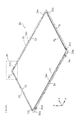
- FIG. 4A is an external perspective view of the cell guide when viewed obliquely from the front according to one or more embodiments.
- FIG. 4B is an enlarged view of the region A1 in FIG. 4A .
- FIG. 5 is an external perspective view of the cell guide when viewed obliquely from the back according to one or more embodiments.
- a right-portion cell guide 31, a left-portion cell guide 32, an upper-portion cell guide 33, and a lower-portion cell guide 34 are disposed in positions respectively corresponding to four sides of the backlight unit 40.
- the right-portion cell guide 31 may be disposed in a position corresponding to a side on a right end of the backlight unit 40
- the left-portion cell guide 32 may be disposed in a position corresponding to a side on a left end of the backlight unit 40
- the upper-portion cell guide 33 may be disposed in a position corresponding to a side on an upper end of the backlight unit 40
- the lower-portion cell guide 34 may be disposed in a position corresponding to a side on a lower end of the backlight unit 40.
- incised clinch portions 31c, 32c, 33c, 34c for determining the position of the liquid crystal cell 20 may be formed in positions respectively corresponding to the four sides of the backlight unit 40.
- the incised clinch portion 31c that regulates the liquid crystal cell 20 so as to move to a right side may be formed on both end portions thereof.
- the incised clinch portion 32c that regulates the liquid crystal cell 20 so as to move to a left side may be formed on both end portions thereof.
- the incised clinch portion 33c that regulates the liquid crystal cell 20 so as to move to an upper side may be formed on both end portions thereof.
- the incised clinch portion 34c that regulates the liquid crystal cell 20 so as to move to a lower side may be formed on both end portions thereof.
- a cushion member 74 acting as a third protective member may be respectively disposed on a surface on an inner side of each incised clinch portion 31c, 32c, 33c, 34c.
- the cushion member 74 may be of a material similar to that of the cushion members 72, 73.
- the cell guide 30, as illustrated in FIG. 5 may comprise a first support portion 30a, which may press a front surface side of the peripheral edge portion of the backlight unit 40, and a second support portion 30b, which may be formed continuously from an outer peripheral edge of the first support portion 30a toward a back surface side and disposed to a side of the backlight unit 40.
- the right-portion cell guide 31, the left-portion cell guide 32, the upper-portion cell guide 33, and the lower-portion cell guide 34, which may configure the cell guide 30, may be each formed by press processing an elongated plate-shaped member made of metal so that a cross section is L-shaped.
- the right-portion cell guide 31 may comprise a first right-portion cell guide 31 a, which is a portion configuring a right side of the first support portion 30a, and a second right-portion cell guide 31b, which is a portion configuring a right side of the second support portion 30b.
- the left-portion cell guide 32 may comprise a first left-portion cell guide 32a, which is a portion configuring a left side of the first support portion 30a, and a second left-portion cell guide 32b, which is a portion configuring a left side of the second support portion 30b.
- the upper portion cell guide 33 may comprise a first upper-portion cell guide 33a, which is a portion configuring an upper side of the first support portion 30a, and a second upper-portion cell guide 33b, which is a portion configuring an upper side of the second support portion 30b.
- the lower portion cell guide 34 may comprise a first lower-portion cell guide 34a, which is a portion configuring a lower side of the first support portion 30a, and a second lower-portion cell guide 34b, which is a portion configuring a lower side of the second support portion 30b.
- press processing may be performed not only to form the first support portion 30a and the second support portion 30b but also to form the eight incised clinch portions 31c, 32c, 33c, 34c on each cell guide 31 to 34.
- the display device 100 may further comprise a position regulating portion 55 for regulating the cell guide 30, the plurality of optical sheets 41 to 43, and the light-guide plate 44 so as to move relatively in either the vertical or the lateral direction relative to the front cabinet 10 or the rear frame 50.
- through-holes 33e, 34e acting as a third penetration portion may be formed near a center in the lateral direction in the upper-portion cell guide 33 and the lower-portion cell guide 34, respectively.
- FIG. 6 is an exploded perspective view that enlarges portions according to one or more embodiments, which correspond to a through-hole of an upper-portion cell guide, of the upper-portion cell guide, an optical sheet, a light-guide plate, and a rear frame.
- through-hole forming portions 41a, 42a, 43a of sheet shapes that project toward an upper portion may be respectively formed near a center in the lateral direction of an upper portion of the plurality of optical sheets 41 to 43.
- through-holes 41b, 42b, 43b acting as a second penetration portion may be formed, in each through-hole forming portion 41a, 42a, 43a, in a position coinciding with the through-hole 33e on the X-Y plane.
- the plurality of optical sheets 41 to 43 may comprise the through-hole forming portions 41a, 42a, 43a, which may be regions for forming the through-holes 41b, 42b, 43b.
- a pair of projecting portions 44a that acts as a first penetration portion and projects upward at a position coinciding with lateral outer sides of the through-hole 33e may be formed.
- a width between the pair of projecting portions 44a and a width in the lateral direction of the through-hole 33e may be formed so as to coincide.
- the first penetration portion formed in the light-guide plate may be formed as a through-hole.
- the rear frame 50 may comprise a protruding portion 50a that may extend frontward from a back surface thereof and may penetrate the through-holes 33e, 41b, 42b, 43b and a space between the pair of projecting portions 44a.
- this upper-portion cell guide 33, plurality of optical sheets 41 to 43, and light-guide plate 44 each may be disposed in a predetermined position on the rear frame 50 by each through-hole 33e, 41b, 42b, 43b and the space between the pair of projecting portions 44a being stacked in a state of being penetrated by the projecting portion 44a of the rear frame 50.
- the entirety of the outer peripheral edge of the plurality of optical sheets 41 to 43 and the light-guide plate 44, respectively, is disposed so as to overlap the cell guide 30.
- the position regulating portion 55 may comprise the protruding portion 50a of the rear frame 50; the through-hole 33e of the upper-portion cell guide 33 of the cell guide 30; the through-holes 41b, 42b, 43b of the plurality of optical sheets 41 to 43; and the projecting portion 44a of the light-guide plate 44.
- the cell guide 30 position regulates the liquid crystal cell 20 by the eight incised clinch portions 31c, 32c, 33c, 34c so that the liquid crystal cell 20 does not move in the vertical and lateral directions relative to the cell guide 30, the enclosure 4, the liquid crystal cell 20, the cell guide 30, and the backlight unit 40 are each in a state where movement in the vertical and lateral directions is regulated relatively.
- a protruding portion for penetrating the through-hole 33e of the upper-portion cell guide 33 of the cell guide 30, the through-holes 41b, 42b, 43b of the plurality of optical sheets 41 to 43, and the projecting portion 44a of the light-guide plate 44, which act as the first to third penetration portions, does not have to be formed on the rear frame 50 and may be formed on the front cabinet 10.
- a position regulating portion may be of any form able to regulate movement of the cell guide 30 and the backlight unit 40 in the vertical and lateral directions relative to the enclosure 4.
- FIG. 7 is an exploded perspective view of the cell guide according to one or more embodiments.
- the right-portion cell guide 31, the left-portion cell guide 32, the upper-portion cell guide 33, and the lower-portion cell guide 34, which configure the cell guide 30, each may have fastening holes 31d, 32d, 33d, 34d for being fastened to a member adjacent to both ends.
- the cell guide 30 may be screwed in place in a state of being assembled as in FIG. 4A .
- the fastening holes 31d, 32d, 33d, 34d may be formed in the second support portion 30b but may be formed in the first support portion 30a.
- the cell guide 30 is screwed in place from the vertical and lateral directions.
- the cell guide may be screwed in place from the longitudinal direction.
- the right-portion cell guide 31, the left-portion cell guide 32, the upper-portion cell guide 33, and the lower-portion cell guide 34 do not need to be fastened by being screwed in place and may be fastened with rivets, by crimping after overlapping each end portion, by using a snap fit, or by welding or deposition.
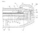
- FIG. 8 is an enlarged cross-sectional view of a right side of a display device according to one or more embodiments of a second example cut along the line A-A in FIG. 1 .
- reference numbers identical to reference numbers in one or more embodiments of the first example will be assigned to elements that are identical or substantially similar to elements described in one or more embodiments of the first example. Because of this, description of these elements will be omitted.
- a driver circuit 90 that is connected to the liquid crystal cell 20 is disposed to a side of the cell guide 30.
- an insulating member 91 may be provided between the cell guide 30 and the driver circuit 90 when the driver circuit 90 is disposed to the side of the cell guide 30.
- the cell guide 30 may be subjected to an insulating treatment for being insulated from the driver circuit 90, which is an example of an electrical component, from among a plurality of electrical components, disposed to the side of the cell guide 30.
- the insulating member 91 does not have to be disposed as in FIG. 8 , and the insulating treatment may be for example obtained by affixing an insulating sheet on a surface on a driver circuit 90 side of the cell guide 30.
- the driver circuit 90 can be prevented from being shorted by the cell guide 30 when, for example, the driver circuit 90 contacts the cell guide 30 due to an impact from the outside. By this, a failure of the driver circuit 90 or another electrical component due to shorting via the cell guide 30 can be prevented.
- FIG. 9 is an enlarged cross-sectional view of a right side of a display device according to one or more embodiments of a third example cut along the line A-A in FIG. 1 .
- reference numbers identical to reference numbers in one or more embodiments of the first example and one or more embodiments of the second example will be assigned to elements identical or substantially similar to elements described in one or more embodiments of the first example and one or more embodiments of the second example. Because of this, description of these elements will be omitted.
- the driver circuit 90 that is disposed with the liquid crystal cell 20 in a manner similar to that of one or more embodiments of the second example is disposed to the side of the cell guide 30.
- an insulating member 91a with high thermal conductivity thermally connects the cell guide 30 and the driver circuit 90.
- the cell guide 30 and the driver circuit 90 from among the plurality of electrical components, disposed to the side of the cell guide 30 are thermally connected by the insulating member 91a comprising a material with high thermal conductivity, heat generated by the driver circuit 90 can be dissipated efficiently by the cell guide 30, which may comprise the metal material and have a high thermal conductivity and heat radiation properties.
- One or more embodiments of the present invention is useful as a display device-for example, a liquid crystal display, a liquid crystal television, or the like-that can reduce the thickness and narrow the frame while strengthening the display panel.
Landscapes
- Physics & Mathematics (AREA)
- Nonlinear Science (AREA)
- Mathematical Physics (AREA)
- Chemical & Material Sciences (AREA)
- Crystallography & Structural Chemistry (AREA)
- General Physics & Mathematics (AREA)
- Optics & Photonics (AREA)
- Liquid Crystal (AREA)
- Devices For Indicating Variable Information By Combining Individual Elements (AREA)
Applications Claiming Priority (1)
| Application Number | Priority Date | Filing Date | Title |
|---|---|---|---|
| JP2013170810A JP2015040921A (ja) | 2013-08-20 | 2013-08-20 | 表示装置およびその支持部材 |
Publications (2)
| Publication Number | Publication Date |
|---|---|
| EP2840436A2 true EP2840436A2 (de) | 2015-02-25 |
| EP2840436A3 EP2840436A3 (de) | 2015-06-10 |
Family
ID=51453585
Family Applications (1)
| Application Number | Title | Priority Date | Filing Date |
|---|---|---|---|
| EP14181094.5A Withdrawn EP2840436A3 (de) | 2013-08-20 | 2014-08-14 | Anzeigevorrichtung und Stützelement dafür |
Country Status (3)
| Country | Link |
|---|---|
| US (1) | US20150055053A1 (de) |
| EP (1) | EP2840436A3 (de) |
| JP (1) | JP2015040921A (de) |
Cited By (2)
| Publication number | Priority date | Publication date | Assignee | Title |
|---|---|---|---|---|
| CN109491140A (zh) * | 2018-11-30 | 2019-03-19 | 青岛海信电器股份有限公司 | 一种显示装置 |
| CN109633960A (zh) * | 2019-01-29 | 2019-04-16 | 惠州市华星光电技术有限公司 | 液晶显示模组及液晶显示装置 |
Families Citing this family (18)
| Publication number | Priority date | Publication date | Assignee | Title |
|---|---|---|---|---|
| US20170146727A1 (en) * | 2014-06-06 | 2017-05-25 | Sharp Kabushiki Kaisha | Display device and television receiver device |
| CN204348262U (zh) * | 2015-01-04 | 2015-05-20 | 京东方科技集团股份有限公司 | 一种显示装置及其框体组件 |
| CN105259703B (zh) * | 2015-11-09 | 2019-01-15 | 深圳市华星光电技术有限公司 | 一种背光模组及显示装置 |
| KR102609458B1 (ko) * | 2016-11-28 | 2023-12-01 | 엘지디스플레이 주식회사 | 액정 표시 장치 |
| WO2018109804A1 (ja) * | 2016-12-12 | 2018-06-21 | 三菱電機株式会社 | 表示機器 |
| CN109923602B (zh) * | 2017-08-09 | 2021-01-29 | 瑞仪(广州)光电子器件有限公司 | 框架组件及显示设备 |
| US10859759B2 (en) | 2017-09-26 | 2020-12-08 | Panasonic Intellectual Property Management Co., Ltd. | Image display apparatus |
| JP7001434B2 (ja) * | 2017-11-10 | 2022-01-19 | シャープ株式会社 | 表示装置 |
| JP6986981B2 (ja) * | 2018-01-22 | 2021-12-22 | 三菱電機株式会社 | バックライトおよび表示装置 |
| JP7106223B2 (ja) * | 2019-01-21 | 2022-07-26 | アルパイン株式会社 | 表示装置 |
| KR102461660B1 (ko) * | 2019-01-24 | 2022-11-01 | 엘지전자 주식회사 | 디스플레이 디바이스 |
| CN110488523B (zh) * | 2019-08-13 | 2024-07-19 | 武汉恒生光电产业有限公司 | 液晶显示器及其安装方法 |
| CN110596953A (zh) * | 2019-08-13 | 2019-12-20 | 武汉恒生光电产业有限公司 | 一种液晶显示器及其背光模组 |
| JP2021131502A (ja) * | 2020-02-21 | 2021-09-09 | 船井電機株式会社 | 表示装置 |
| CN113253478A (zh) * | 2021-05-20 | 2021-08-13 | 武汉华星光电技术有限公司 | 显示装置 |
| CN114093244A (zh) * | 2021-11-18 | 2022-02-25 | 武汉华星光电技术有限公司 | 背光模组及电子装置 |
| CN119620279A (zh) * | 2023-09-14 | 2025-03-14 | 镭亚电子(苏州)有限公司 | 背光模组和显示装置 |
| JP7612941B1 (ja) * | 2024-09-13 | 2025-01-14 | Eizo株式会社 | 電子機器および表示装置 |
Citations (1)
| Publication number | Priority date | Publication date | Assignee | Title |
|---|---|---|---|---|
| JP2009134269A (ja) | 2007-10-29 | 2009-06-18 | Sharp Corp | 表示装置 |
Family Cites Families (1)
| Publication number | Priority date | Publication date | Assignee | Title |
|---|---|---|---|---|
| JP5032650B2 (ja) * | 2010-12-27 | 2012-09-26 | 株式会社東芝 | テレビおよび電子機器 |
-
2013
- 2013-08-20 JP JP2013170810A patent/JP2015040921A/ja active Pending
-
2014
- 2014-08-12 US US14/457,876 patent/US20150055053A1/en not_active Abandoned
- 2014-08-14 EP EP14181094.5A patent/EP2840436A3/de not_active Withdrawn
Patent Citations (1)
| Publication number | Priority date | Publication date | Assignee | Title |
|---|---|---|---|---|
| JP2009134269A (ja) | 2007-10-29 | 2009-06-18 | Sharp Corp | 表示装置 |
Cited By (4)
| Publication number | Priority date | Publication date | Assignee | Title |
|---|---|---|---|---|
| CN109491140A (zh) * | 2018-11-30 | 2019-03-19 | 青岛海信电器股份有限公司 | 一种显示装置 |
| CN109491140B (zh) * | 2018-11-30 | 2021-06-08 | 海信视像科技股份有限公司 | 一种显示装置 |
| CN109633960A (zh) * | 2019-01-29 | 2019-04-16 | 惠州市华星光电技术有限公司 | 液晶显示模组及液晶显示装置 |
| CN109633960B (zh) * | 2019-01-29 | 2021-08-24 | 惠州市华星光电技术有限公司 | 液晶显示模组及液晶显示装置 |
Also Published As
| Publication number | Publication date |
|---|---|
| EP2840436A3 (de) | 2015-06-10 |
| JP2015040921A (ja) | 2015-03-02 |
| US20150055053A1 (en) | 2015-02-26 |
Similar Documents
| Publication | Publication Date | Title |
|---|---|---|
| EP2840436A2 (de) | Anzeigevorrichtung und Stützelement dafür | |
| US8704974B2 (en) | Backlight assembly comprising a light-sourcing unit fixing frame with a lateral extension portion and a fixing protrusion which interlocks the light-sourcing unit fixing frame to a housing | |
| JP5657763B2 (ja) | 表示装置、液晶表示装置 | |
| US9910213B2 (en) | Display with heat radiation | |
| EP2587302B1 (de) | Anzeigevorrichtung und TV-Gerät | |
| US8355096B2 (en) | Illumination device and liquid crystal display device including the same | |
| US9052430B2 (en) | Illumination apparatus, display apparatus, and electronic device | |
| US20140247398A1 (en) | Display | |
| US20120236207A1 (en) | Liquid Crystal Display Device, Liquid Crystal Television Set, and Television Set | |
| JP2014153438A (ja) | 表示装置 | |
| WO2014073425A1 (ja) | 照明装置、表示装置、及びテレビ受信装置 | |
| JP2012104232A (ja) | 光源装置、画像表示装置、及び、テレビジョン受像機 | |
| WO2013191051A1 (ja) | 表示装置、及びテレビ受信装置 | |
| JP2014170079A (ja) | 表示装置 | |
| JP2014077871A (ja) | 液晶表示装置 | |
| WO2013121944A1 (ja) | 表示装置、及びテレビ受信装置 | |
| US20190121201A1 (en) | Image display apparatus and support pin | |
| EP2587904A1 (de) | Anzeigevorrichtung und Fernseher | |
| JP2015099292A (ja) | 表示装置 | |
| WO2015060272A1 (ja) | 液晶表示装置 | |
| JP4626621B2 (ja) | バックライト装置 | |
| JP5717675B2 (ja) | 表示装置、及びテレビ受信装置 | |
| JP2008257952A (ja) | バックライト装置 | |
| JP2008243558A (ja) | バックライト装置 | |
| KR20150031694A (ko) | 액정표시장치용 에지형 백 라이트 유닛 |
Legal Events
| Date | Code | Title | Description |
|---|---|---|---|
| PUAI | Public reference made under article 153(3) epc to a published international application that has entered the european phase |
Free format text: ORIGINAL CODE: 0009012 |
|
| 17P | Request for examination filed |
Effective date: 20140814 |
|
| AK | Designated contracting states |
Kind code of ref document: A2 Designated state(s): AL AT BE BG CH CY CZ DE DK EE ES FI FR GB GR HR HU IE IS IT LI LT LU LV MC MK MT NL NO PL PT RO RS SE SI SK SM TR |
|
| AX | Request for extension of the european patent |
Extension state: BA ME |
|
| PUAL | Search report despatched |
Free format text: ORIGINAL CODE: 0009013 |
|
| AK | Designated contracting states |
Kind code of ref document: A3 Designated state(s): AL AT BE BG CH CY CZ DE DK EE ES FI FR GB GR HR HU IE IS IT LI LT LU LV MC MK MT NL NO PL PT RO RS SE SI SK SM TR |
|
| AX | Request for extension of the european patent |
Extension state: BA ME |
|
| RIC1 | Information provided on ipc code assigned before grant |
Ipc: G02F 1/1333 20060101AFI20150504BHEP |
|
| STAA | Information on the status of an ep patent application or granted ep patent |
Free format text: STATUS: THE APPLICATION IS DEEMED TO BE WITHDRAWN |
|
| 18D | Application deemed to be withdrawn |
Effective date: 20151211 |