EP2840452A2 - Structure de commande pour une machine de travail mobile, machine de travail mobile et procédé présentant une structure de commande - Google Patents
Structure de commande pour une machine de travail mobile, machine de travail mobile et procédé présentant une structure de commande Download PDFInfo
- Publication number
- EP2840452A2 EP2840452A2 EP20140176642 EP14176642A EP2840452A2 EP 2840452 A2 EP2840452 A2 EP 2840452A2 EP 20140176642 EP20140176642 EP 20140176642 EP 14176642 A EP14176642 A EP 14176642A EP 2840452 A2 EP2840452 A2 EP 2840452A2
- Authority
- EP
- European Patent Office
- Prior art keywords
- power
- coordinator
- energy
- consumer
- control structure
- Prior art date
- Legal status (The legal status is an assumption and is not a legal conclusion. Google has not performed a legal analysis and makes no representation as to the accuracy of the status listed.)
- Granted
Links
Images


Classifications
-
- G—PHYSICS
- G05—CONTROLLING; REGULATING
- G05B—CONTROL OR REGULATING SYSTEMS IN GENERAL; FUNCTIONAL ELEMENTS OF SUCH SYSTEMS; MONITORING OR TESTING ARRANGEMENTS FOR SUCH SYSTEMS OR ELEMENTS
- G05B19/00—Program-control systems
- G05B19/02—Program-control systems electric
- G05B19/04—Program control other than numerical control, i.e. in sequence controllers or logic controllers
- G05B19/042—Program control other than numerical control, i.e. in sequence controllers or logic controllers using digital processors
-
- H—ELECTRICITY
- H02—GENERATION; CONVERSION OR DISTRIBUTION OF ELECTRIC POWER
- H02J—ELECTRIC POWER NETWORKS; CIRCUIT ARRANGEMENTS OR SYSTEMS FOR SUPPLYING OR DISTRIBUTING ELECTRIC POWER; SYSTEMS FOR STORING ELECTRIC ENERGY
- H02J1/00—Circuit arrangements for DC mains or DC distribution networks
- H02J1/14—Balancing load and power generation in DC networks
Definitions
- the invention is based on a control structure for a mobile work machine. Furthermore, the invention is based on a mobile work machine having such a control structure and a method having such a control structure.
- Control structures or energy management strategies for passenger cars (cars) and trucks (trucks) are known from the prior art. These are based on the fact that a drive of the car or truck is a major power consumer. Such energy management strategies therefore have a so-called powertrain coordinator, which coordinates a drive train of the propulsion drive with or without additional hybridization. Secondary consumers outside the driveline are usually an alternator and a compressor for an air conditioner. These usually have a maximum power below 5 KW and thus require less than 5% of a combustion engine power, if it is assumed that this is 100 KW. Therefore, such energy management strategies are focused on the optimization of the drive train including its hydride components.
- a PTO or a power take-off or a working hydraulics for a working arm or for a working function, such as threshing or shredding consume most of the engine power.
- a tractor with a baler high-pressure press during pressing up to 90% of the engine output via the PTO shaft delivered to the baler high-pressure press.
- the remaining engine power is used for the traction drive and ancillaries.
- the press is preferred in the event of a shortage of work because a "standing" Press to clog presses.
- the energy management strategy for cars and trucks which is designed for the drive, is only of limited suitability for mobile work machines. If, for example, the working hydraulics and / or the power take-off shaft are used as secondary consumers, then this energy management strategy leads to complicated special constructions or the secondary consumers can not be used as needed.
- the publication DE 198 57 916 A1 discloses another consumer control structure. This has a superordinate consumer management, which determines the power requirement from the consumers. A co-ordinator records the determined power requirement and makes it available from energy sources. The consumer management then uses the required power to control the consumers.
- the invention has the object to provide a flexible and simply designed control structure for a mobile machine.
- Another object of the invention is to provide a mobile work machine with such a To provide a control structure and a method with such a control structure.
- control structure is achieved according to the features of claim 1, with respect to the mobile working machine according to the features of claim 14 and with respect to the method according to the features of claim 15.
- a control structure for a mobile work machine has consumer energy coordinators, each of which is assigned a controller or a management or a management module for at least one consumer.
- a respective consumer energy coordinator determines a power requirement for the controller (s) controlled by the controller on the basis of desired values of the controller assigned to it.
- a total energy coordinator is provided which communicates with the consumer energy coordinators and determines a total power requirement from the determined power requirements of the consumer energy coordinators. The total energy coordinator then distributes the available power to the consumer energy coordinators.
- This solution has the advantage that a universal control structure for energy management or energy coordination is created.
- the consumer energy coordinators in this case form an energy coordination level and the total energy coordinator a further higher level of energy coordination.
- the control structure according to the invention thus a functional control of the consumer is separated from the energy management.
- Each consumer who receives target values for his function from an operator or from a controller thus has a consumer energy coordinator and, separately therefrom, the controller which controls or regulates the function of the consumption on the basis of the desired value or the setpoint values.
- the consumer energy coordinators can be adapted to their associated control or to their associated consumers and for the total energy coordinator no adjustment is necessary.
- a respective consumer energy coordinator can work with the physical variables of the controller associated with it or the consumer assigned to it.
- the consumer energy coordinators are thus to be understood as a kind of modules or blocks which are adapted to their control or to their consumers, without having to adapt the overall energy coordinator to the different controllers or different consumers. It is thus created a uniform system structure for mobile machines.
- the mobile working machine is, for example, a tractor, a combine harvester, a hydraulic excavator, a wheel loader, a dump truck, a truck with a hydraulic loading crane or a municipal vehicle.
- a consumer energy coordinator for a working hydraulics which usually requires at least 40% (often more than 90%) of a power of an internal combustion engine of the mobile work machine. This determines the power requirement of the working hydraulics based on a demand of a pressure and a flow rate of the working hydraulics. The demand of the pressure and the volume flow can be obtained from the working hydraulics.
- mobile work machines with a variety of work hydraulics can easily communicate with the total energy coordinator of the mobile work machine via the consumer energy coordinator by simply communicating the demand of the pressure and the volume flow to the consumer energy coordinator.
- the other consumer energy coordinators or the total energy coordinator are thus completely independent of the respective design of the working hydraulics.
- the power requirement of the working hydraulics is transmitted by the consumer energy coordinator as torque and / or speed of at least one hydraulic pump (power at the pump shaft) to the total energy coordinator.
- the mobile work machine can have a consumer energy coordinator for a power take-off or a power take-off.
- a PTO shaft is used to drive a wide variety of attachments.
- a consumer energy coordinator for a high-voltage and / or low-voltage electrical system can be provided.
- a consumer energy coordinator for a drive train may be provided.
- the power energy coordinator can transmit the power requirement in the form of a torque and / or a rotational speed to the overall energy coordinator for the drive train. This in turn can transmit a translation specification to the consumer energy coordinator.
- the consumer power co-ordinator for the PTO can transmit to the overall energy coordinator the power demand in the form of a torque and / or a speed.
- the overall energy coordinator in turn can transmit to the consumer energy coordinator a transmission ratio for a transmission of the power take-off shaft.
- At least one energy source for the consumers is controlled as a function of the total power requirement.
- an energy source for example, an internal combustion engine and / or an electric motor are provided.
- a respective energy source can in this case have a control or a management via which it communicates with the overall energy coordinator.
- the internal combustion engine is preferably a diesel engine.
- a generator may be provided, which is driven by the internal combustion engine to charge, for example, an electrical storage and / or to feed electrical energy into the electrical system.
- At least one hydraulic pump can be provided, which is driven by the energy source, in particular by the internal combustion engine.
- a traction drive of the mobile work machine preferably has wheels or chains. These can either be driven by a gearbox from the internal combustion engine or by hydromotors driven by the hydraulic pump. Optionally, they can be operated by an electric motor as a parallel or series hybrid drive.
- the working hydraulics has at least one hydraulic actuator, which is, for example, a hydraulic cylinder or a hydraulic motor.
- the hydraulic actuator can be driven by the hydraulic pump.
- the hydraulic actuators can then be used, for example, as an excavator arm, as a trough in a dump truck, as a shovel in a wheel loader, as a loading crane, as a hoist in a tractor or for lifting implements such as plow or mower.
- a hydraulic accumulator can be provided, can be discharged with the pressure means for driving the hydraulic traction drive or for driving the working hydraulics.
- the energy source or the energy sources are controlled with regard to their consumption-optimal operating point, in particular if the total power requirement is less than the total available power.
- the overall energy coordinator can determine a consumption-optimal speed and / or other selectable parameters of the energy sources. It is thus possible to use a power from a wide variety of energy sources in such a way that the mobile working machine is used in its optimum, in particular consumption-optimal operating point.
- a respective consumer energy coordinator can distribute the power available to him in such a way that the consumers assigned to him are used at their optimum operating point.
- the work machine and / or the consumers are thus operated consumption and / or efficiency optimal.
- a particularly consumption-optimized operation of the mobile work machine on the entire vehicle level and on the subsystem level can be easily achieved.
- the overall energy coordinator prefferably, it is further possible for the overall energy coordinator to prioritize the power available to the consumer energy coordinators, in particular if the total power requirement is greater than the total available power.
- the prioritization is preferably carried out in such a way that the consumer energy coordinators receive sufficient power for safety-relevant consumers, for example for brakes and steering. It is advantageous if a respective consumer energy coordinator prioritizes the power available to him for the consumers assigned to him. The prioritization of consumers is thus simply by the respective consumer energy coordinator. If the total power requirement is greater than the total available power, for example, in a tractor that drives a high-pressure baler, the PTO is prioritized over the traction drive, so that the tractor stops rather than that the PTO is throttled.
- a respective consumer energy coordinator is connected to the total energy coordinator via a uniform interface.
- a respective controller controls the consumer (s) assigned to it on the basis of the desired value or desired values detected by it.
- the total energy coordinator can determine, for example, the total power required relative to the crankshaft of the internal combustion engine. Furthermore, the overall energy coordinator preferably determines not only the total power requirement but also the total available power.
- a power reserve is determined by the total energy coordinator and / or by at least one consumer energy coordinator. This can be used for the operation of a hydraulic brake or a hydraulic steering, for the electrical system, for a transmission or a compressed air brake.
- the overall energy coordinator communicates with a charge controller of a hydraulic accumulator and / or a charge controller of a low-voltage battery and / or a charge controller of a high-voltage battery in order to take this into account in the power distribution.
- the setpoint values for the working hydraulics can be predetermined, for example, by a human interface and / or by a higher-level controller (for example precision farming).
- the mobile work machine may have the PTO shaft.
- the traction drive can be driven, for example, via a transmission by an internal combustion engine and / or by at least one hydraulic motor and / or by an electric motor.
- the hydraulic motor can be supplied at least via a hydraulic pump.
- the working machine can furthermore have a hydraulic accumulator which can be charged in particular by the hydraulic pump. From this pressure medium for driving the hydraulic traction drive or for driving the working hydraulics can be discharged.
- traction drive can also be provided a consumer energy coordinator.
- FIG. 1 a control structure 1 according to the invention for a mobile work machine is shown. This has a total energy coordinator 2, the more consumer coordinators are subordinated 4 to 12. Consumer Coordinators 4 to 12 are Energy Coordinators.
- the consumer coordinator 4 is provided for a working hydraulics. He communicates with the management or the control 14 of the working hydraulics. This has as input variables setpoints 16, which are volume flows and / or pressures. On the output side, the controller 14 has a control 18 for consumers or components. From the desired values 16, the controller 14 determines the required volume flows and pressures, which are reported via an interface 20 to the consumer energy coordinator 4 for the working hydraulics. This in turn determines a power requirement and transmits this via an interface 22 to the total energy coordinator 2.
- the consumer power coordinator 6 is provided for a power take-off shaft.
- the consumer energy coordinator 6 here is assigned a management or a control 24 for the PTO shaft. This also has setpoint values 16 as input, for example a rotational speed, and has on the output side the drive 18 for the power take-off shaft, for example a gear ratio.
- the control 24 of the PTO is connected to the consumer energy coordinator 6, which in turn is connected via an interface 28 with the total energy coordinator 2.
- the consumer energy coordinator 8 is provided for a driveline. This is assigned to a management or control 30 of the drive train. This has as input 16 setpoints and has as output the drive 18 for the drive train.
- the controller 30 is connected via an interface 32 to the consumer energy coordinator 8. This in turn is connected via an interface 34 with the total energy coordinator 2.
- NV-board network For a low-voltage electrical system (NV-board network) of the consumer energy coordinator 10 is provided.
- This is a management or a controller Assigned 36 for low-voltage consumers, the setpoints 16, for example, a power as an input and the control 18 has as an output.
- the controller 36 is connected via an interface 38 with the consumer energy coordinator 10 and this in turn via an interface 40 with the total energy coordinator 2.
- the consumer energy coordinator 12 is assigned to a high-voltage vehicle electrical system (HV vehicle electrical system).
- the consumer energy coordinator 12 in this case interacts with a management or a controller 42 for high-voltage consumers.
- the controller 42 has setpoint values 16 on the input side, for example a power, and on the output side the control 18, with which consumers are controlled. Via an interface 44, the controller 42 is connected to the consumer energy coordinator 12. This in turn is connected via an interface 46 with the total energy coordinator 2.
- the total energy coordinator 2 is further connected directly via an interface 48 with a management or a control for an internal combustion engine. On the output side, this has a drive 18, via which the loads connected to the controller 50, that is to say in particular the internal combustion engine, are actuated.
- the total energy coordinator 2 is connected directly via an interface 52 to a management or a controller 54 for an electric motor.
- the controller 54 has a control 18 for the loads connected to the controller 54, that is to say for at least one electric motor.
- the frame 56 in FIG. 1 illustrates that outside of the energy management a functional control for consumers is provided, which is in principle responsible for the implementation of a driver's request.
- the control 14 for the working hydraulics receives setpoint values from a human interface or a higher-level controller and calculates therefrom the necessary volume flows and pressures, which are then reported to the higher-level consumer energy coordinator 4. This determines from this the necessary power to a pump shaft or pump waves and reports this to the total energy coordinator 2.
- the other consumer coordinators 6 to 12 also report the power required to implement the setpoints.
- the total energy coordinator 2 then calculates an overall power requirement from the power requirements, in particular with reference to a crankshaft of the internal combustion engine.
- the operating strategy of the overall coordinator 2 determines a consumption-optimal speed or other selectable parameters of the system for providing the necessary power requirement. Furthermore, by the operating strategy of the total energy coordinator 2, a consumption-optimal reference of the required total line requirements from different sources, such as internal combustion engine and / or electric drive with memory, allows. For this purpose, it presets desired values to the controller 50 of the internal combustion engine and to the controller 54 of the electric motor. The other consumer energy coordinators 4 to 12 in turn can in turn specify optimal operating points of the consumers assigned to them. A consumption-optimized operation of the mobile work machine thus takes place on the entire vehicle level and also on the subsystem level.
- the overall energy coordinator 2 carries out a corresponding prioritization of the subordinate consumer energy coordinators 4 to 12.
- this block 56 has, for example, a power requirement 58a of an air conditioner and / or a power requirement 58b in the form of an output torque of a wheel of the work machine and / or a power requirement 58c in the form of a torque of the PTO shaft and / or a power demand 58d in the form of an electric power and or a power requirement 58e in the form of power for a power outlet of an implement and / or a power requirement 58f in the form of power for the working hydraulics.
- the block 56 has a speed actual value 60 of the working machine and a speed 62 of the internal combustion engine and / or the electric motor and / or the PTO.
- the power requirements 58a to 58f are communicated to the total energy coordinator 2, inter alia, by the consumer energy coordinator 4 to 12.
- the block 56 transmits the total power requirement to a block 66, which represents an operating strategy (hybrid strategy / switching strategy).
- the latter also has the speed 62 and the speed actual value 60 as input variables.
- it receives a reserved power from the block 70 via the connection 68.
- the block 70 serves to determine a power reserve for the working hydraulics (brake / steering) and / or for one On-board network (12-volt vehicle electrical system) and / or for a gearbox and / or for a compressed-air brake.
- the power reserve is further transmitted via a connection 72 to a block 74, which is used to determine the available power.
- This receives on the input side a power limit 76 of an accumulator and / or a power limit 78 of a battery and / or a possible torque of the combustion, electric and / or - hydraulic motor 80.
- he has as input the actual speed value 60.
- the determined by the block 74 available Power is communicated over a link 82 to the block 66 with the operating strategy.
- the block 66 has as additional input variables a charging requirement of a pressure accumulator (hydraulic accumulator) via the connection 84 and / or a charging requirement of a low-voltage battery via the connection 86 and / or a charging requirement of a high-voltage battery via the connection 88.
- the connection 84 thereby connects block 66 with a block 90, which provides a charge controller for the hydraulic accumulator.
- block 66 is connected to a block 92 which has a charge controller for the low-voltage battery.
- a charge controller for the high-voltage battery is represented by the block 94, which is connected via the connection 88 to the block 66.
- the block 90 so the charge controller of the hydraulic accumulator, has as input the state of charge 96.
- the block 92 so the charge controller of the low-voltage battery, has as input the state of charge 98 of the low-voltage battery and the charge controller for the high-voltage battery, respectively the block 94, has as input a state of charge 100 of the high-voltage battery.
- Another input to the operating strategy of block 66 may be a drive mode default 102.
- the performance requirements 58a to 58f are also communicated to the block 58 and thus to the operating strategy in addition to the block 58.
- setpoints are provided in the operating strategy with block 66.
- target values is a setpoint speed 104 or setpoint torque for the internal combustion engine and / or a setpoint torque 106 for the electric motor and / or a setpoint torque 108 for the hydraulic motor and / or a desired ratio for a transmission 110 and / or a desired ratio 112 for the PTO and / or a target power for a DC / DC converter and / or generator 114 is provided.
- the energy sources are controlled with these desired variables.
- Another block 116 of the total energy coordinator 2 is used to determine the maximum allowable power of a respective consumer or the prioritization of the consumer with insufficient power.
- the power requirements 58a to 58f are provided.
- Another input represents the available power with the connection 82.
- the block 116 is communicated with the connections 118 a reserved power of individual subsystems.
- the services allocated to the consumers are then provided, which are transmitted to the consumer energy coordinators 4 to 12. For example, maximum power 120 for air conditioning, maximum power 122 for the work hydraulics, maximum power 124 for the high-voltage loads, and maximum power 126 for the low-voltage loads are provided.
- Block 128 is used to determine the required volume flow of the first hydraulic circuit and, via block 130, the required volume flow of the second hydraulic circuit.
- the block 128 has volume flow setpoints 132a to 132d of the first hydraulic circuit.
- the block 130 has volume flow values 134a to 134d of the second hydraulic circuit as input variable.
- both blocks 128 and 130 are reported as further input variables possible overloads 136a to 136d.
- the determined volumetric flow setpoint values of blocks 128 and 130 are then reported via a connection 138 or 140, respectively, to a block 142, which serves as connection of the hydraulic circuits and provides as output a control 144 of the connection.
- a Pump synchronization pressure
- a required pressure of a first hydraulic pump is determined, and in block 150 a required pressure of a second is determined.
- the overloads 136a to 136d are provided and actual pressures 152a to 152d.
- the pressure determined in the block 148 is also communicated via a connection 152 to the block 154 and the pressure determined in the block 150 via a connection 156 also to the block 154.
- the block 154 which receives the volume flow setpoint values of the hydraulic circuits via the connection 138 and 140 as further input variables, determines a desired power requirement of the hydraulic pumps. This results in a required drive power or a required torque or a required speed for the hydraulic pumps (deliverable pump power), which is supplied via the output 158 the total energy coordinator 2. From this, the consumer energy coordinator 4 receives via input 160 the drive power or torque or rotational speed available for the hydraulic pumps, which is supplied to block 162 of consumer energy coordinator 4.
- block 168 This provides for the power limitation of the hydraulic pumps and has on the input side via the connection 152 and 156 the required pump pressure.
- maximum powers 164, 166 are provided for the hydraulic pumps.
- a distribution of the available volume flow to the consumer is provided via the block 168 of the consumer energy coordinator 4, with safety-relevant consumers, such as the steering or the trailer brake, are taken into account.
- the input variables for block 168 are volumetric flow actual values 170, 172 of the hydraulic pumps. Another input is a parameter of an operating mode 174.
- block 168 is supplied with volumetric flow setpoints 176a.
- an operating mode default 178 and transition boundary conditions 180 are provided as an input.
- block 168 has maximum volume flows 182a-182d for the consumers.
- the consumer energy coordinator 10 for the low-voltage electrical system provides a determination of a consumer demand in a block 184.
- powers 186a-186c are provided.
- An output of block 184 provides a power requirement 188 that is a 12 volt power request is. This is transmitted to the total energy coordinator 2.
- a block 190 of the consumer energy coordinator 10 serves to determine the distributable power.
- the input used here is a power 192 (available low-voltage consumer power).
- a block 194 communicates a security feature reserve over block 196 to block 190.
- the block 190 has the determined distributable power, which is reported via a connection 198 to a block 200.
- a further block 204 of the consumer energy coordinator 10 provides a drive 208 for a DC / DC converter or generator. As input for the block 204, a nominal power 206 is provided for the DC / DC converter or generator, which is transmitted by the total energy coordinator 2.
- FIG. 5 is the consumer energy coordinator 12 shown for the high-voltage electrical system.
- a consumer demand is determined via a block 210.
- a power 212 for an electric air-conditioning compressor and / or a power 214 for an electrical socket and / or a power 216 for a cooling fan serve as input variables.
- a power requirement 218 power request high-voltage vehicle electrical system consumers
- An available power 220 is then transmitted by the total energy coordinator 2 to a block 222 of the consumer power coordinator 12. This is then an available power 220 for the high-voltage consumers.
- Block 222 determines the distributable power, which is then communicated over link 224 to block 226, which is responsible for allocating power to the consumers.
- a block 228 relates to the reserve for security functions, which is communicated via a connection 230 to the block 222 and the block 226.
- the services 212 to 216 are provided.
- the block 226 On the output side, the block 226 then has an available power 232 for the air conditioning compressor and / or an available power 234 for the power outlet and / or an available power 236 for the cooling fan.
- the consumer energy coordinator 6 is shown for the PTO.
- This has a block 238 as PTO speed controller.
- PTO speed controller This has as an input a Zapfwellenist loftiere 240.
- a PTO nominal speed 242 is provided.
- the PTO speed controller is connected via a connection 244 to a block 246, which is responsible for the power requirement of the PTO.
- This transmits a power requirement 248 of the power take-off shaft to the total energy coordinator 2.
- a desired crankshaft torque is determined.
- the block 250 is also connected via the connection 244 to the block 238 and has on the output side a PTO target torque 252 (relative to the crankshaft) for the total energy coordinator 2.
- Block 256 is the control of a translation. This receives via an input 258 a specification of a transmission ratio of the total energy coordinator 2. An output of the block 256 provides a drive signal 260 for the translation before.
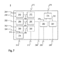
- the consumer power coordinator 8 for the driveline is in FIG. 7 shown.
- This has a block 262 for a cruise control, which has as an input a target speed 264 and an actual speed 266. It is connected to a block 270 via a connection 268. This determines a power requirement or a torque requirement (desired power / desired torque). The power requirement 272 or torque requirement is then transmitted to the total energy coordinator 2.
- a block 274 is used to set a translation. This has as input a translation instruction 276. On the output side, the block 274 is connected via a connection 278 to a block 280 and a connection 282 to a block 284.
- Block 280 represents the control for a hydrostatic drive and block 284 the control of a manual transmission or clutches. As output of the block 280, drive signals 286 for a pump or a motor are provided. As output of the block 284, drive signals 288 for the clutches or gear steps are provided.
- Another block 290 of the consumer energy coordinator 8 provides a control of a hydraulic hybrid motor.
- a setpoint torque input 292 for the hydraulic hybrid motor is provided as an input.
- the block 290 is connected via a connection 294 to a block 296, which serves for valve control.
- the block 296 provides on the output side drive signals 298 for the motor.
- a block 300 is used for coordination with respect to an all-wheel or a traction. As input for the block 300, a load distribution 302 on one axis and / or a load distribution 304 on one side are provided.
- the block 300 is connected via a connection 306 to a block 308 which serves to control locks or couplings.
- the block 308 provides on the output side activation signals 310 for locks or couplings.
- the block 300 is further connected via a connection 312 to a block 314 which serves to control additional hydraulic motors.
- the block 314 provides on the output side drive signals 316 for the hydraulic motors.
- the control structure according to the FIGS. 1 to 7 has the advantage that a machine integrator can simply buy software modules, including energy management, or have them created in-house by various departments. Here the uniform interfaces are helpful.
- the various consumer energy coordinators are domain specific except for the total energy coordinator. So if a domain is not installed, this consumer energy coordinator can simply be omitted. Creating a consumer energy coordinator requires only domain-specific expertise. Uniform, domain-specific physical quantities can be used in each domain. It is simply a separation of functional control and energy management allows. The energy management of a future work machine with the most diverse work modes, which can hardly be surveyed without this control structure, can be divided into meaningful understandable blocks with logical interfaces.
- a control structure for a mobile work machine This has consumer energy coordinators, each of which is assigned at least one controller for at least one consumer. From a respective consumer coordinator a power requirement for the controller (s) controlled by the controller is determined on the basis of nominal values of the controller or controllers assigned to it. An overall energy requirement is then determined from the power requirements determined by the consumer energy coordinators via a total energy coordinator. The total energy coordinator then divides the available power to the consumer energy coordinators, who in turn split this on the controls or consumers.
Landscapes
- Physics & Mathematics (AREA)
- General Physics & Mathematics (AREA)
- Engineering & Computer Science (AREA)
- Automation & Control Theory (AREA)
- Electric Propulsion And Braking For Vehicles (AREA)
- Control Of Vehicle Engines Or Engines For Specific Uses (AREA)
- Operation Control Of Excavators (AREA)
Applications Claiming Priority (1)
| Application Number | Priority Date | Filing Date | Title |
|---|---|---|---|
| DE201310214732 DE102013214732A1 (de) | 2013-07-29 | 2013-07-29 | Steuerungsstruktur für eine mobile Arbeitsmaschine, mobile Arbeitsmaschine und Verfahren mit einer Steuerungsstruktur |
Publications (3)
| Publication Number | Publication Date |
|---|---|
| EP2840452A2 true EP2840452A2 (fr) | 2015-02-25 |
| EP2840452A3 EP2840452A3 (fr) | 2015-08-12 |
| EP2840452B1 EP2840452B1 (fr) | 2017-04-12 |
Family
ID=51178736
Family Applications (1)
| Application Number | Title | Priority Date | Filing Date |
|---|---|---|---|
| EP14176642.8A Not-in-force EP2840452B1 (fr) | 2013-07-29 | 2014-07-11 | Structure de commande pour une machine de travail mobile, machine de travail mobile et procédé présentant une structure de commande |
Country Status (3)
| Country | Link |
|---|---|
| EP (1) | EP2840452B1 (fr) |
| CN (1) | CN104346519A (fr) |
| DE (1) | DE102013214732A1 (fr) |
Cited By (3)
| Publication number | Priority date | Publication date | Assignee | Title |
|---|---|---|---|---|
| DE102018218024A1 (de) | 2018-10-22 | 2020-04-23 | Robert Bosch Gmbh | Steuerungsstruktur für eine mobile Arbeitsmaschine, Verfahren und mobile Arbeitsmaschine |
| EP3643572A1 (fr) * | 2018-10-25 | 2020-04-29 | Robert Bosch GmbH | Commande pour une machine de travail, procédé et machine de travail |
| WO2023036674A1 (fr) * | 2021-09-13 | 2023-03-16 | Robert Bosch Gmbh | Unité de commande pour un entraînement et entraînement ayant une unité de commande |
Families Citing this family (6)
| Publication number | Priority date | Publication date | Assignee | Title |
|---|---|---|---|---|
| DE102016215834A1 (de) | 2016-08-23 | 2018-03-01 | Continental Teves Ag & Co. Ohg | Verfahren zum Betreiben einer Druckregelvorrichtung sowie Druckregelvorrichtung zur Durchführung des Verfahrens |
| DE102017106629A1 (de) * | 2017-03-28 | 2018-10-04 | Ghh Fahrzeuge Gmbh | Verfahren zum Betrieb eines selbstfahrenden Untertagefahrzeugs |
| DE102019208319A1 (de) | 2018-07-17 | 2020-01-23 | Robert Bosch Gmbh | Antriebssteuerungsanordnung für eine mobile Arbeitsmaschine und Schnittstelle |
| DE102020208103A1 (de) | 2020-06-30 | 2021-12-30 | Robert Bosch Gesellschaft mit beschränkter Haftung | Steuerungsstruktur für eine mobile Arbeitsmaschine, mobile Arbeitsmaschine mit der Steuerungsstruktur, Verfahren mit der Steuerungsstruktur |
| DE102021212135A1 (de) | 2021-10-27 | 2023-04-27 | Zf Friedrichshafen Ag | Verfahren zur Verteilung von Leistung eines elektrischen Antriebsstrangs einer Arbeitsmaschine, Steuereinrichtung, Computerprogrammprodukt und Arbeitsmaschine |
| DE102022209466A1 (de) | 2022-09-12 | 2024-03-14 | Robert Bosch Gesellschaft mit beschränkter Haftung | Verfahren zur Steuerung einer mobilen Arbeitsmaschine |
Citations (2)
| Publication number | Priority date | Publication date | Assignee | Title |
|---|---|---|---|---|
| DE19857916A1 (de) | 1998-12-15 | 2000-06-21 | Bosch Gmbh Robert | Verfahren und Vorrichtung zur Steuerung von elektrischen Verbrauchern in einem Fahrzeug |
| DE19709317B4 (de) | 1997-03-07 | 2008-04-30 | Robert Bosch Gmbh | Verfahren und Vorrichtung zur Steuerung eines Fahrzeugs |
Family Cites Families (7)
| Publication number | Priority date | Publication date | Assignee | Title |
|---|---|---|---|---|
| DE102005047011A1 (de) * | 2005-09-30 | 2007-04-05 | Ford Global Technologies, LLC, Dearborn | Energiesteuervorrichtung für ein Kraftfahrzeug |
| US7795752B2 (en) * | 2007-11-30 | 2010-09-14 | Caterpillar Inc | System and method for integrated power control |
| IT1395088B1 (it) * | 2009-03-12 | 2012-09-05 | Rolic Invest Sarl | Veicolo battipista e metodo di controllo dello stesso |
| JP5220679B2 (ja) * | 2009-04-20 | 2013-06-26 | 住友重機械工業株式会社 | ハイブリッド型作業機械及びハイブリッド型作業機械の制御方法 |
| SE535475C2 (sv) * | 2010-08-26 | 2012-08-21 | Atlas Copco Rock Drills Ab | Metod och system för styrning av en kraftkälla vid en bergborrningsanordning samt bergborrningsanordning |
| DE102010044906A1 (de) * | 2010-09-09 | 2012-03-15 | Robert Bosch Gmbh | Verfahren zum Vergeben eines Betriebspunktes einer Antriebsmaschine eines Antriebssystems |
| US8606448B2 (en) * | 2011-06-29 | 2013-12-10 | Caterpillar Inc. | System and method for managing power in machine having electric and/or hydraulic devices |
-
2013
- 2013-07-29 DE DE201310214732 patent/DE102013214732A1/de not_active Withdrawn
-
2014
- 2014-07-11 EP EP14176642.8A patent/EP2840452B1/fr not_active Not-in-force
- 2014-07-28 CN CN201410361641.XA patent/CN104346519A/zh active Pending
Patent Citations (2)
| Publication number | Priority date | Publication date | Assignee | Title |
|---|---|---|---|---|
| DE19709317B4 (de) | 1997-03-07 | 2008-04-30 | Robert Bosch Gmbh | Verfahren und Vorrichtung zur Steuerung eines Fahrzeugs |
| DE19857916A1 (de) | 1998-12-15 | 2000-06-21 | Bosch Gmbh Robert | Verfahren und Vorrichtung zur Steuerung von elektrischen Verbrauchern in einem Fahrzeug |
Cited By (4)
| Publication number | Priority date | Publication date | Assignee | Title |
|---|---|---|---|---|
| DE102018218024A1 (de) | 2018-10-22 | 2020-04-23 | Robert Bosch Gmbh | Steuerungsstruktur für eine mobile Arbeitsmaschine, Verfahren und mobile Arbeitsmaschine |
| EP3643572A1 (fr) * | 2018-10-25 | 2020-04-29 | Robert Bosch GmbH | Commande pour une machine de travail, procédé et machine de travail |
| WO2023036674A1 (fr) * | 2021-09-13 | 2023-03-16 | Robert Bosch Gmbh | Unité de commande pour un entraînement et entraînement ayant une unité de commande |
| CN118019931A (zh) * | 2021-09-13 | 2024-05-10 | 罗伯特·博世有限公司 | 用于驱动器的控制单元和带有控制单元的驱动器 |
Also Published As
| Publication number | Publication date |
|---|---|
| DE102013214732A1 (de) | 2015-02-26 |
| EP2840452B1 (fr) | 2017-04-12 |
| CN104346519A (zh) | 2015-02-11 |
| EP2840452A3 (fr) | 2015-08-12 |
Similar Documents
| Publication | Publication Date | Title |
|---|---|---|
| EP2840452B1 (fr) | Structure de commande pour une machine de travail mobile, machine de travail mobile et procédé présentant une structure de commande | |
| DE102019208422A1 (de) | Verbessertes Bremsverfahren und -vorrichtung für Hybridmaschinen | |
| EP2190710A2 (fr) | Procédé pour déplacer le point de charge en fonctionnement hybride pour un véhicule à fonctionnement hybride en parallèle | |
| DE102013224383A1 (de) | Leistungsverzweigter Achsantrieb für Arbeitsmaschinen | |
| DE102014224337A1 (de) | Verfahren zur Steuerung eines hydrostatischen Antriebs | |
| DE102007002080A1 (de) | Fahrzeug mit einem elektrisch angetriebenen Fahrmodus | |
| EP2428419B1 (fr) | Procédé de programmation d'un point de fonctionnement d'un système d'entraînement | |
| EP2994357A1 (fr) | Procédé permettant de déterminer un paramètre de contrôle d'un régulateur de puissance ou de répartition de couple pour un entraînement hybride d'un engin de travail | |
| EP2500197A2 (fr) | Entraînement hybride relié par engrenage auxiliaire | |
| DE102022210721A1 (de) | System und verfahren zur traktionssteuerung in einem arbeitsfahrzeug mit einem stufenlosen e-getriebe | |
| WO2020187905A1 (fr) | Procédé permettant de faire fonctionner une chaîne cinématique d'une machine de travail, chaîne cinématique pour une machine de travail et machine de travail | |
| DE102023101526A1 (de) | Hybrides Antriebssystem für eine Arbeitsmaschine und Verfahren zur Steuerung eines solchen | |
| DE102008025683B4 (de) | Verfahren zur Ansteuerung eines Fahrantriebs | |
| EP0554544B1 (fr) | Véhicules avec machine à combustion interne suralimentable à l'aide d'une turbosoufflante à gaz d'échappement et commande hydrostatique-mécanique des agrégats auxiliaires | |
| WO2024170397A1 (fr) | Procédé de mise fonctionnement d'un groupe motopropulseur d'un engin de chantier, groupe motopropulseur pour un engin de chantier et engin de chantier | |
| DE102018218863A1 (de) | Verfahren zum Betrieb eines Antriebssystems, Antriebssystem und Arbeitsmaschine | |
| DE19955313A1 (de) | Antriebssystem für Flurförderzeuge | |
| EP2988979B1 (fr) | Stratégie de fonctionnement pour véhicules hybrides pour effectuer un déplacement du point de charge, une récupération et une suralimentation | |
| EP3940155B1 (fr) | Structure de commande pour machine de travail mobile, machine de travail mobile dotée de la structure de commande, procédé comportant la structure de commande | |
| DE102012112381A1 (de) | Antriebsachse eines Fahrzeugs mit einer einen hydraulischen Druckmittelspeicher umfassenden Energierückgewinnungseinrichtung | |
| EP2818675A1 (fr) | Commande pour le système d'entraînement d'une machine de travail | |
| DE102019214405B4 (de) | Elektrischer Antriebstrang für Arbeitsmaschinen | |
| DE102012001367A1 (de) | Hydrostatischer Hybridantrieb sowie Fahrzeug mit einem hydrostatischen Hybridantrieb | |
| CH706518A1 (de) | Steuerung für das Antriebssystem einer Arbeitsmaschine. | |
| EP3088264B1 (fr) | Systeme de ralentisseur d'un train de vehicule automobile |
Legal Events
| Date | Code | Title | Description |
|---|---|---|---|
| PUAI | Public reference made under article 153(3) epc to a published international application that has entered the european phase |
Free format text: ORIGINAL CODE: 0009012 |
|
| 17P | Request for examination filed |
Effective date: 20140711 |
|
| AK | Designated contracting states |
Kind code of ref document: A2 Designated state(s): AL AT BE BG CH CY CZ DE DK EE ES FI FR GB GR HR HU IE IS IT LI LT LU LV MC MK MT NL NO PL PT RO RS SE SI SK SM TR |
|
| AX | Request for extension of the european patent |
Extension state: BA ME |
|
| PUAL | Search report despatched |
Free format text: ORIGINAL CODE: 0009013 |
|
| AK | Designated contracting states |
Kind code of ref document: A3 Designated state(s): AL AT BE BG CH CY CZ DE DK EE ES FI FR GB GR HR HU IE IS IT LI LT LU LV MC MK MT NL NO PL PT RO RS SE SI SK SM TR |
|
| AX | Request for extension of the european patent |
Extension state: BA ME |
|
| RIC1 | Information provided on ipc code assigned before grant |
Ipc: H02J 1/14 20060101ALI20150709BHEP Ipc: G05B 19/042 20060101AFI20150709BHEP |
|
| R17P | Request for examination filed (corrected) |
Effective date: 20160212 |
|
| RBV | Designated contracting states (corrected) |
Designated state(s): AL AT BE BG CH CY CZ DE DK EE ES FI FR GB GR HR HU IE IS IT LI LT LU LV MC MK MT NL NO PL PT RO RS SE SI SK SM TR |
|
| 17Q | First examination report despatched |
Effective date: 20160309 |
|
| GRAP | Despatch of communication of intention to grant a patent |
Free format text: ORIGINAL CODE: EPIDOSNIGR1 |
|
| INTG | Intention to grant announced |
Effective date: 20170126 |
|
| RIN1 | Information on inventor provided before grant (corrected) |
Inventor name: SCHLEYER, MARKUS Inventor name: LOPEZ PAMPLONA, ALEJANDRO Inventor name: FASSNACHT, JOCHEN |
|
| GRAS | Grant fee paid |
Free format text: ORIGINAL CODE: EPIDOSNIGR3 |
|
| GRAA | (expected) grant |
Free format text: ORIGINAL CODE: 0009210 |
|
| AK | Designated contracting states |
Kind code of ref document: B1 Designated state(s): AL AT BE BG CH CY CZ DE DK EE ES FI FR GB GR HR HU IE IS IT LI LT LU LV MC MK MT NL NO PL PT RO RS SE SI SK SM TR |
|
| REG | Reference to a national code |
Ref country code: GB Ref legal event code: FG4D Free format text: NOT ENGLISH |
|
| REG | Reference to a national code |
Ref country code: CH Ref legal event code: EP |
|
| REG | Reference to a national code |
Ref country code: IE Ref legal event code: FG4D Free format text: LANGUAGE OF EP DOCUMENT: GERMAN |
|
| REG | Reference to a national code |
Ref country code: AT Ref legal event code: REF Ref document number: 884489 Country of ref document: AT Kind code of ref document: T Effective date: 20170515 |
|
| REG | Reference to a national code |
Ref country code: DE Ref legal event code: R096 Ref document number: 502014003363 Country of ref document: DE |
|
| REG | Reference to a national code |
Ref country code: NL Ref legal event code: MP Effective date: 20170412 |
|
| REG | Reference to a national code |
Ref country code: LT Ref legal event code: MG4D |
|
| PG25 | Lapsed in a contracting state [announced via postgrant information from national office to epo] |
Ref country code: NL Free format text: LAPSE BECAUSE OF FAILURE TO SUBMIT A TRANSLATION OF THE DESCRIPTION OR TO PAY THE FEE WITHIN THE PRESCRIBED TIME-LIMIT Effective date: 20170412 |
|
| PG25 | Lapsed in a contracting state [announced via postgrant information from national office to epo] |
Ref country code: LT Free format text: LAPSE BECAUSE OF FAILURE TO SUBMIT A TRANSLATION OF THE DESCRIPTION OR TO PAY THE FEE WITHIN THE PRESCRIBED TIME-LIMIT Effective date: 20170412 Ref country code: GR Free format text: LAPSE BECAUSE OF FAILURE TO SUBMIT A TRANSLATION OF THE DESCRIPTION OR TO PAY THE FEE WITHIN THE PRESCRIBED TIME-LIMIT Effective date: 20170713 Ref country code: HR Free format text: LAPSE BECAUSE OF FAILURE TO SUBMIT A TRANSLATION OF THE DESCRIPTION OR TO PAY THE FEE WITHIN THE PRESCRIBED TIME-LIMIT Effective date: 20170412 Ref country code: NO Free format text: LAPSE BECAUSE OF FAILURE TO SUBMIT A TRANSLATION OF THE DESCRIPTION OR TO PAY THE FEE WITHIN THE PRESCRIBED TIME-LIMIT Effective date: 20170712 Ref country code: FI Free format text: LAPSE BECAUSE OF FAILURE TO SUBMIT A TRANSLATION OF THE DESCRIPTION OR TO PAY THE FEE WITHIN THE PRESCRIBED TIME-LIMIT Effective date: 20170412 Ref country code: ES Free format text: LAPSE BECAUSE OF FAILURE TO SUBMIT A TRANSLATION OF THE DESCRIPTION OR TO PAY THE FEE WITHIN THE PRESCRIBED TIME-LIMIT Effective date: 20170412 |
|
| PGFP | Annual fee paid to national office [announced via postgrant information from national office to epo] |
Ref country code: IT Payment date: 20170731 Year of fee payment: 4 |
|
| PG25 | Lapsed in a contracting state [announced via postgrant information from national office to epo] |
Ref country code: LV Free format text: LAPSE BECAUSE OF FAILURE TO SUBMIT A TRANSLATION OF THE DESCRIPTION OR TO PAY THE FEE WITHIN THE PRESCRIBED TIME-LIMIT Effective date: 20170412 Ref country code: SE Free format text: LAPSE BECAUSE OF FAILURE TO SUBMIT A TRANSLATION OF THE DESCRIPTION OR TO PAY THE FEE WITHIN THE PRESCRIBED TIME-LIMIT Effective date: 20170412 Ref country code: IS Free format text: LAPSE BECAUSE OF FAILURE TO SUBMIT A TRANSLATION OF THE DESCRIPTION OR TO PAY THE FEE WITHIN THE PRESCRIBED TIME-LIMIT Effective date: 20170812 Ref country code: RS Free format text: LAPSE BECAUSE OF FAILURE TO SUBMIT A TRANSLATION OF THE DESCRIPTION OR TO PAY THE FEE WITHIN THE PRESCRIBED TIME-LIMIT Effective date: 20170412 Ref country code: PL Free format text: LAPSE BECAUSE OF FAILURE TO SUBMIT A TRANSLATION OF THE DESCRIPTION OR TO PAY THE FEE WITHIN THE PRESCRIBED TIME-LIMIT Effective date: 20170412 Ref country code: BG Free format text: LAPSE BECAUSE OF FAILURE TO SUBMIT A TRANSLATION OF THE DESCRIPTION OR TO PAY THE FEE WITHIN THE PRESCRIBED TIME-LIMIT Effective date: 20170712 |
|
| REG | Reference to a national code |
Ref country code: DE Ref legal event code: R097 Ref document number: 502014003363 Country of ref document: DE |
|
| PG25 | Lapsed in a contracting state [announced via postgrant information from national office to epo] |
Ref country code: CZ Free format text: LAPSE BECAUSE OF FAILURE TO SUBMIT A TRANSLATION OF THE DESCRIPTION OR TO PAY THE FEE WITHIN THE PRESCRIBED TIME-LIMIT Effective date: 20170412 Ref country code: EE Free format text: LAPSE BECAUSE OF FAILURE TO SUBMIT A TRANSLATION OF THE DESCRIPTION OR TO PAY THE FEE WITHIN THE PRESCRIBED TIME-LIMIT Effective date: 20170412 Ref country code: SK Free format text: LAPSE BECAUSE OF FAILURE TO SUBMIT A TRANSLATION OF THE DESCRIPTION OR TO PAY THE FEE WITHIN THE PRESCRIBED TIME-LIMIT Effective date: 20170412 Ref country code: DK Free format text: LAPSE BECAUSE OF FAILURE TO SUBMIT A TRANSLATION OF THE DESCRIPTION OR TO PAY THE FEE WITHIN THE PRESCRIBED TIME-LIMIT Effective date: 20170412 Ref country code: RO Free format text: LAPSE BECAUSE OF FAILURE TO SUBMIT A TRANSLATION OF THE DESCRIPTION OR TO PAY THE FEE WITHIN THE PRESCRIBED TIME-LIMIT Effective date: 20170412 |
|
| PLBE | No opposition filed within time limit |
Free format text: ORIGINAL CODE: 0009261 |
|
| STAA | Information on the status of an ep patent application or granted ep patent |
Free format text: STATUS: NO OPPOSITION FILED WITHIN TIME LIMIT |
|
| PG25 | Lapsed in a contracting state [announced via postgrant information from national office to epo] |
Ref country code: SM Free format text: LAPSE BECAUSE OF FAILURE TO SUBMIT A TRANSLATION OF THE DESCRIPTION OR TO PAY THE FEE WITHIN THE PRESCRIBED TIME-LIMIT Effective date: 20170412 |
|
| REG | Reference to a national code |
Ref country code: CH Ref legal event code: PL |
|
| 26N | No opposition filed |
Effective date: 20180115 |
|
| REG | Reference to a national code |
Ref country code: IE Ref legal event code: MM4A |
|
| REG | Reference to a national code |
Ref country code: FR Ref legal event code: ST Effective date: 20180330 |
|
| PG25 | Lapsed in a contracting state [announced via postgrant information from national office to epo] |
Ref country code: IE Free format text: LAPSE BECAUSE OF NON-PAYMENT OF DUE FEES Effective date: 20170711 Ref country code: LI Free format text: LAPSE BECAUSE OF NON-PAYMENT OF DUE FEES Effective date: 20170731 Ref country code: CH Free format text: LAPSE BECAUSE OF NON-PAYMENT OF DUE FEES Effective date: 20170731 |
|
| PG25 | Lapsed in a contracting state [announced via postgrant information from national office to epo] |
Ref country code: FR Free format text: LAPSE BECAUSE OF NON-PAYMENT OF DUE FEES Effective date: 20170731 Ref country code: SI Free format text: LAPSE BECAUSE OF FAILURE TO SUBMIT A TRANSLATION OF THE DESCRIPTION OR TO PAY THE FEE WITHIN THE PRESCRIBED TIME-LIMIT Effective date: 20170412 |
|
| REG | Reference to a national code |
Ref country code: BE Ref legal event code: MM Effective date: 20170731 |
|
| PG25 | Lapsed in a contracting state [announced via postgrant information from national office to epo] |
Ref country code: LU Free format text: LAPSE BECAUSE OF NON-PAYMENT OF DUE FEES Effective date: 20170711 |
|
| PG25 | Lapsed in a contracting state [announced via postgrant information from national office to epo] |
Ref country code: BE Free format text: LAPSE BECAUSE OF NON-PAYMENT OF DUE FEES Effective date: 20170731 |
|
| PG25 | Lapsed in a contracting state [announced via postgrant information from national office to epo] |
Ref country code: MT Free format text: LAPSE BECAUSE OF FAILURE TO SUBMIT A TRANSLATION OF THE DESCRIPTION OR TO PAY THE FEE WITHIN THE PRESCRIBED TIME-LIMIT Effective date: 20170412 |
|
| GBPC | Gb: european patent ceased through non-payment of renewal fee |
Effective date: 20180711 |
|
| PG25 | Lapsed in a contracting state [announced via postgrant information from national office to epo] |
Ref country code: GB Free format text: LAPSE BECAUSE OF NON-PAYMENT OF DUE FEES Effective date: 20180711 |
|
| PG25 | Lapsed in a contracting state [announced via postgrant information from national office to epo] |
Ref country code: MC Free format text: LAPSE BECAUSE OF FAILURE TO SUBMIT A TRANSLATION OF THE DESCRIPTION OR TO PAY THE FEE WITHIN THE PRESCRIBED TIME-LIMIT Effective date: 20170412 Ref country code: HU Free format text: LAPSE BECAUSE OF FAILURE TO SUBMIT A TRANSLATION OF THE DESCRIPTION OR TO PAY THE FEE WITHIN THE PRESCRIBED TIME-LIMIT; INVALID AB INITIO Effective date: 20140711 |
|
| PG25 | Lapsed in a contracting state [announced via postgrant information from national office to epo] |
Ref country code: IT Free format text: LAPSE BECAUSE OF NON-PAYMENT OF DUE FEES Effective date: 20180711 |
|
| PG25 | Lapsed in a contracting state [announced via postgrant information from national office to epo] |
Ref country code: CY Free format text: LAPSE BECAUSE OF FAILURE TO SUBMIT A TRANSLATION OF THE DESCRIPTION OR TO PAY THE FEE WITHIN THE PRESCRIBED TIME-LIMIT Effective date: 20170412 |
|
| PG25 | Lapsed in a contracting state [announced via postgrant information from national office to epo] |
Ref country code: MK Free format text: LAPSE BECAUSE OF FAILURE TO SUBMIT A TRANSLATION OF THE DESCRIPTION OR TO PAY THE FEE WITHIN THE PRESCRIBED TIME-LIMIT Effective date: 20170412 |
|
| PG25 | Lapsed in a contracting state [announced via postgrant information from national office to epo] |
Ref country code: TR Free format text: LAPSE BECAUSE OF FAILURE TO SUBMIT A TRANSLATION OF THE DESCRIPTION OR TO PAY THE FEE WITHIN THE PRESCRIBED TIME-LIMIT Effective date: 20170412 |
|
| PG25 | Lapsed in a contracting state [announced via postgrant information from national office to epo] |
Ref country code: PT Free format text: LAPSE BECAUSE OF FAILURE TO SUBMIT A TRANSLATION OF THE DESCRIPTION OR TO PAY THE FEE WITHIN THE PRESCRIBED TIME-LIMIT Effective date: 20170412 |
|
| PG25 | Lapsed in a contracting state [announced via postgrant information from national office to epo] |
Ref country code: AL Free format text: LAPSE BECAUSE OF FAILURE TO SUBMIT A TRANSLATION OF THE DESCRIPTION OR TO PAY THE FEE WITHIN THE PRESCRIBED TIME-LIMIT Effective date: 20170412 |
|
| REG | Reference to a national code |
Ref country code: AT Ref legal event code: MM01 Ref document number: 884489 Country of ref document: AT Kind code of ref document: T Effective date: 20190711 |
|
| PG25 | Lapsed in a contracting state [announced via postgrant information from national office to epo] |
Ref country code: AT Free format text: LAPSE BECAUSE OF NON-PAYMENT OF DUE FEES Effective date: 20190711 |
|
| PGFP | Annual fee paid to national office [announced via postgrant information from national office to epo] |
Ref country code: DE Payment date: 20230922 Year of fee payment: 10 |
|
| REG | Reference to a national code |
Ref country code: DE Ref legal event code: R119 Ref document number: 502014003363 Country of ref document: DE |
|
| PG25 | Lapsed in a contracting state [announced via postgrant information from national office to epo] |
Ref country code: DE Free format text: LAPSE BECAUSE OF NON-PAYMENT OF DUE FEES Effective date: 20250201 |