EP2840933B1 - Panneau arrière d'un tiroir - Google Patents
Panneau arrière d'un tiroir Download PDFInfo
- Publication number
- EP2840933B1 EP2840933B1 EP13720749.4A EP13720749A EP2840933B1 EP 2840933 B1 EP2840933 B1 EP 2840933B1 EP 13720749 A EP13720749 A EP 13720749A EP 2840933 B1 EP2840933 B1 EP 2840933B1
- Authority
- EP
- European Patent Office
- Prior art keywords
- drawer
- rear wall
- stiffening device
- plate
- mounted position
- Prior art date
- Legal status (The legal status is an assumption and is not a legal conclusion. Google has not performed a legal analysis and makes no representation as to the accuracy of the status listed.)
- Active
Links
Images




Classifications
-
- A—HUMAN NECESSITIES
- A47—FURNITURE; DOMESTIC ARTICLES OR APPLIANCES; COFFEE MILLS; SPICE MILLS; SUCTION CLEANERS IN GENERAL
- A47B—TABLES; DESKS; OFFICE FURNITURE; CABINETS; DRAWERS; GENERAL DETAILS OF FURNITURE
- A47B88/00—Drawers for tables, cabinets or like furniture; Guides for drawers
- A47B88/90—Constructional details of drawers
-
- A—HUMAN NECESSITIES
- A47—FURNITURE; DOMESTIC ARTICLES OR APPLIANCES; COFFEE MILLS; SPICE MILLS; SUCTION CLEANERS IN GENERAL
- A47B—TABLES; DESKS; OFFICE FURNITURE; CABINETS; DRAWERS; GENERAL DETAILS OF FURNITURE
- A47B88/00—Drawers for tables, cabinets or like furniture; Guides for drawers
- A47B88/90—Constructional details of drawers
- A47B88/941—Drawers being constructed from two or more parts
-
- A—HUMAN NECESSITIES
- A47—FURNITURE; DOMESTIC ARTICLES OR APPLIANCES; COFFEE MILLS; SPICE MILLS; SUCTION CLEANERS IN GENERAL
- A47B—TABLES; DESKS; OFFICE FURNITURE; CABINETS; DRAWERS; GENERAL DETAILS OF FURNITURE
- A47B88/00—Drawers for tables, cabinets or like furniture; Guides for drawers
- A47B88/90—Constructional details of drawers
- A47B2088/902—Corner connectors for drawers
Definitions
- the present invention relates to a rear wall for a drawer with the features of the preamble of claim 1, a drawer with such a rear wall and a piece of furniture with at least one such drawer.
- GB 376,518A shows a triangular reinforcing metal frame for connecting the side walls with the front or the rear wall.
- the object of the invention is to provide a comparison with the prior art improved rear wall for a drawer, a drawer with such a rear wall and a piece of furniture with such a drawer.
- the rear wall has at least one additional stiffening device separate from the rear wall brackets for increasing the stability of the sheet metal, which can be connected to the metal sheet, preferably detachably, makes it possible, if necessary, for such Reinforcement can be retrofitted to an existing drawer to increase the stability of the rear wall.
- the same sheets can be used for different drawers, which extend substantially over the entire width of the drawer.
- a stiffening device is not necessary, only the sheet is used for the rear wall, in a drawer in which a more stable rear wall is needed, a same sheet is used and there is an additional - but preferably two - such stiffening device for use.
- the at least one stiffening device lies at least partially between the drawer side walls of the drawer in the mounting position of the rear wall on the drawer.
- the at least one stiffening device in the mounting position of the rear wall of the drawer is substantially completely located between the drawer side walls of the drawer.
- the at least one stiffening device is in mounting position of the rear wall of the drawer next to the rear wall brackets of the drawer.
- the at least one stiffening device in the mounting position of the rear wall of the drawer has a lateral distance to the rear wall brackets.
- the at least one stiffening device is formed in one piece.
- the stiffening device is made of sheet metal.
- a bottom of the embossment in the assembly position of the at least one stiffening device is spaced from the metal sheet.
- the at least one stiffening device in the mounting position has a lateral distance from the edge of the sheet.
- a stiffening device has a lateral distance to a left edge of the sheet and a further stiffening device has a lateral distance to a right edge of the sheet.
- the at least one stiffening device has a U-shaped cross-section in an upper region in the mounted position.
- the flap in the mounting position - after bending - prevents removal of at least one stiffening device from the sheet.
- protection is desired for a drawer with a rear wall according to at least one of the described embodiments.
- Protection is also desired for a piece of furniture with such a drawer according to at least one of the described embodiments.
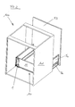
- FIGS. 1 and 2 show two different perspective views of a piece of furniture 100.
- the furniture 100 in this case has a furniture body 101 and arranged therein a drawer 50.
- the drawer 50 has a rail guide system 56, with which the drawer 50 can be moved relative to the furniture body 101. Furthermore, the drawer 50 has a front panel 53 and a rear wall 10.
- the rear wall 10 consists of a substantially over the entire width of the drawer 50 extending sheet 11 and an attached stiffening device 1 to increase the stability of the sheet 11 and thus the rear wall 10th
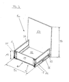
- FIG. 3 shows a perspective view of a drawer 50.
- the drawer 50 has a drawer bottom 52, two drawer side walls 54 and 55, a front panel 53 and a rear wall 10.
- the two drawer side walls 54 and 55 are connected via the two rear wall brackets 21 and 22 to the rear wall 10.
- the rear wall 10 in this case has a metal sheet 11, which extends substantially over the entire width 51 of the drawer 50.
- two stiffening devices 1 are attached in this preferred embodiment in order to increase the stability of the rear wall 10.
- FIG. 3 a rear wall 10 is shown for a drawer 50, with a substantially extending over the entire width 51 of the drawer 50 sheet metal 11, wherein the rear wall 10 is held in the mounting position in the range of drawer side walls 54 and 55 of the drawer 50 of rear wall brackets 21 and 22, the rear wall brackets 21 and 22 being in communication with the drawer side walls 54 and 55, the rear wall 10 in this preferred embodiment having 2 additional stiffening devices 1 separate from the rear wall brackets 21 and 22 for increasing the stability of the sheet metal 11 which is connectable to the sheet 11 are.
- stiffening devices 1 are in mounting position of the rear wall 10 on the drawer 50 between the drawer side walls 54 and 55 of the drawer 50.
- reinforcing devices 1 lie in the mounting position of the rear wall 10 on the drawer 50 next to the rear wall brackets 21 and 22 of the drawer 50.
- the stiffening devices 1 - preferably by means of a screw - were subsequently mounted on the plate 11.
- the height 54 of the front panel 53 is at least twice - preferably at least three times - as large as the height 13 of the sheet 11.
- the stiffening device 1 has a positive effect on the stability the rear wall 10, since the forces acting on the rear wall 10, in such drawers 50, in which the front panel 53 is much higher than the rear wall 10, larger.
- the stiffening device 1 - more precisely, the two stiffening devices 1 - connected to the sheet 11 on a side facing away from the front panel 53 side 16 of the sheet 11, whereby the interior of the drawer 50 is not limited by the fastening device 1 and further a aesthetic back wall 10 is achievable for a viewer.
- the stiffening device 1 in mounting position on the sheet 11 has a lateral distance from the edge of the sheet 11.
- one stiffening device 1 has a lateral distance to the left edge of the sheet 11 in the mounting position and the other stiffening device 1 has a lateral distance to the right edge of the sheet 11.
- FIGS. 4 to 7 show a first variant of a stiffening device. 1
- stiffening device 1 is preferably formed in one piece. This stiffening device 1 is also preferably made of a sheet.
- the stiffening device 1 has a U-shaped cross section 19, which corresponds to a web 12 or a profiled portion of the sheet 11, not shown here (see FIGS. 11 to 15 ).
- the stiffening device 1 in this case has laterally folded-over webs 2 and 3, which extend substantially vertically in the mounting position of the stiffening device 1 and abut with their end faces 4 on the sheet 11 (see FIGS. 11 to 15 ).
- an opening 5 is formed, with which the stiffening device 1 can be screwed to a drawer bottom, not shown here (see FIG. 14 ).
- a flap 6 bendable in the direction of the sheet 11 is formed, which has an opening 8 for introducing a tool 51 (see FIG FIG. 12 ) for bending the flap 6.
- FIG. 4 is shown how the flap 6 has not been bent in the FIG. 6 it is shown how the flap 6 has already been bent.
- FIGS. 8 and 9 a second variant of a stiffening device 1 is shown, which has no flap 6. Instead, in order to increase the stability of the stiffening device 1, an embossment 7 is formed.
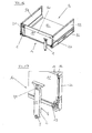
- FIGS. 10 to 13 the individual steps of the assembly of the stiffening device 1 on the sheet 11 of the rear wall 10 are shown in perspective.
- the stiffening device 1 with its upper portion, which has a U-shaped cross section 19, slipped over the folded-over web 12 of the sheet 11. Subsequently, the end faces 4 of the folded webs 2 and 3 (web 3 not visible here, see Figures 5 and 7 ) of the stiffening device 1 on the sheet 11 at ( FIG. 11 . 12, 13 ).
- the tab 6 of the stiffening device 1 is not yet bent in this state. Now you put a tool 51 in the opening 8 of the flap 6 and bends with this tool 51, the flap 6 in the direction of the sheet 11 (FIG. FIG. 12 ).
- the stiffening device 1 After removal of the tool 51 ( FIG. 13 ), the stiffening device 1 can no longer be lifted from the sheet 11, since the curved web 6 prevents this.
- the stiffening device 1 is screwed in its lower region through the opening 5 with the plate 11 and a drawer bottom 52, not shown here (see FIG. 14 ). Thus, the assembly process is completed.
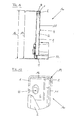
- FIGS. 14 and 15 is a side view of an already mounted stiffening device 1 on the plate 11 shown - as well as the situation in the FIG. 13 reflects.
- the stiffening device 1 in its mounting position extends in its height 16 substantially above the height 13 of the metal sheet 11. In this preferred embodiment, it is even so that the stiffening device 1 protrudes beyond the plate 11 both at its upper and at its lower end, thereby gripping both the upper end of the sheet 11 and the lower end of the sheet 11.
- the stiffening device 1 is fastened by means of a screw, not shown here, to the drawer bottom 52, this being done through an opening in the stiffening device 1 and through an opening in the metal sheet 11. Otherwise that applies under the FIG. 13 Mentioned.
- FIG. 15 shows a detailed view of the upper portion of the rear wall 10 as in the FIG. 14 shown.
- FIG. 15 is clearly visible how the stiffening device 1 in mounting position the profiled portion of the sheet 11 - which is formed in this embodiment as a folded bridge 12 - surrounds and thus allows a good grip of the fastening device 1 on the plate 11.
- the bending of the flap 6 of the flap 6 moves under the beveled web 12 of the sheet 11, whereby a lifting of the stiffening device 1 from the sheet 11 is no longer possible.
- the upper region of the stiffening device 1 has a U-shaped cross-section 19, which surrounds the bevelled web 12 of the metal sheet 11.
- FIGS. 16 to 19 is now shown in perspective view, as the second variant of the stiffening device 1 at a substantially over the entire width 51 (see FIG. 3 ) of the drawer 50 extending sheet 11 can be mounted.
- this second variant of the stiffening device 1 does not have a bendable flap as the first variant (see FIGS. 10 to 13
- This stamping 7 serves to increase the stability of the stiffening device 1, which subsequently also leads to an increase in the stability of the sheet 11, on which the stiffening device 1 - in this preferred embodiment detachable - can be fastened.
- the bottom 9 of the embossment 7 in the mounting position of the stiffening device 1 is spaced from the sheet 11 and is thus not on the sheet 11 at.
- the folded-over webs 2 and 3 of the stiffening device 1 are very well with their end face 4 on the sheet 11 to increase the stability of the sheet 11 and thus the stability of the rear wall 10.
- the drawer 50 has side walls 54 and 55 and also a drawer bottom 52 and a rail extension system 56.
- the opening 5 of the stiffening device 1 and the opening 15 of the sheet metal 11 can be seen well, by means of which the stiffening device 1 can preferably be fastened to the sheet metal 11 with a screw and subsequently to the drawer bottom 52.
- the stiffening device 1 is a separate subassembly which serves to increase the stability of the metal sheet 11 and which, in these exemplary embodiments, is preferably detachably connectable to the metal sheet 11.
- the stiffening device 1 in mounting position has a lateral distance to the edge of the sheet 11, wherein a stiffening device in mounting position has a lateral distance to the left edge of the sheet 11 and the second stiffening device 1 a lateral distance to the right edge of the sheet 11th having.
Landscapes
- Drawers Of Furniture (AREA)
- Finishing Walls (AREA)
Claims (15)
- Paroi arrière (10) pour un tiroir (50), avec une tôle (11) s'étendant globalement sur toute la largeur (51) du tiroir (50), la paroi arrière (10) étant maintenue dans une position de montage au niveau de parois latérales de tiroir (54, 55) du tiroir (50) par des supports de paroi arrière (21, 22), les supports de paroi arrière (21, 22) étant reliés avec les parois latérales de tiroir (54, 55),
caractérisée en ce que la paroi arrière (10) comprend, à l'extérieur, au moins un, de préférence deux, dispositifs de rigidification (1) supplémentaires séparés des supports de paroi arrière (21, 22), afin d'augmenter la solidité de la tôle (11), qui peut être relié avec la tôle (11) de préférence de manière amovible, une position de fixation de l'au moins un dispositif de rigidification (1) pouvant être choisie librement le long de la largeur (51) de la tôle (11). - Paroi arrière selon la revendication 1, caractérisée en ce que l'au moins un dispositif de rigidification (1) se trouve, dans la position de montage de la paroi arrière (10) sur le tiroir (50), au moins partiellement, de préférence globalement entièrement, entre les parois latérales de tiroir (54, 55) du tiroir (50).
- Paroi arrière selon l'une des revendications 1 ou 2, caractérisée en ce que l'au moins un dispositif de rigidification (1) se trouve, dans la position de montage de la paroi arrière (10) sur le tiroir (50), à proximité des supports de paroi arrière (21, 22) du tiroir (50), de préférence l'au moins un dispositif de rigidification (1) présentant, dans la position de montage de la paroi arrière (10) sur le tiroir (50), une distance latérale par rapport aux supports de paroi arrière (21, 22).
- Paroi arrière selon l'une des revendications 1 à 3, caractérisée en ce que la tôle (11) comprend, le long de son extrémité supérieure, une nervure retournée (12) ou une portion profilée, l'au moins un dispositif de rigidification (1) correspondant à la nervure (12) ou à la portion profilée, de préférence l'au moins un dispositif de rigidification (1) enveloppant, dans la position de montage, la nervure (12) ou la portion profilée de la tôle (11).
- Paroi arrière selon l'une des revendications 1 à 4, caractérisée en ce que l'au moins un dispositif de rigidification (1) s'étend, dans la position de montage, globalement sur toute la hauteur (13) de la tôle (11).
- Paroi arrière selon l'une des revendications 1 à 5, caractérisée en ce que l'au moins un dispositif de rigidification (1) comprend au moins une, de préférence deux, nervures retournées (2, 3) qui s'appuient, dans la position de montage de l'au moins un dispositif de rigidification (1), avec sa face frontale (4), contre la tôle (11).
- Paroi arrière selon la revendication 6, caractérisée en ce que la nervure retournée (2, 3) s'étend verticalement dans la position de montage.
- Paroi arrière selon l'une des revendications 1 à 7, caractérisée en ce que l'au moins un dispositif de rigidification (1) comprend, au niveau de son extrémité inférieure, une ouverture (5) à travers laquelle le dispositif de rigidification (1) peut être fixé contre la tôle (11), de préférence à l'aide d'une vis.
- Paroi arrière selon l'une des revendications 1 à 8, caractérisée en ce que l'au moins un dispositif de rigidification (1) comprend, dans la position de montage, au moins une languette (6) pliable en direction de la tôle (11), de préférence avec une ouverture (8) pour l'insertion d'un outil (51) pour le pliage de la languette (6).
- Paroi arrière selon l'une des revendications 1 à 9, caractérisée en ce que l'au moins un dispositif de rigidification (1) comprend, dans la position de montage, au moins un estampage (7) orienté en direction de la tôle (11).
- Tiroir (50) avec une paroi arrière (10) selon l'une des revendications 1 à 10.
- Tiroir selon la revendication 11, le tiroir (50) comprenant un fond de tiroir (52), caractérisé en ce que l'au moins un dispositif de rigidification (1) peut être fixé, de préférence à l'aide d'une vis, à travers l'ouverture (5) dans l'au moins un dispositif de rigidification (1) et à travers une ouverture (15) dans la tôle (11) sur le fond du tiroir (52).
- Tiroir selon la revendication 11 ou 12, le tiroir (50) comprenant un cache frontal (53) caractérisé en ce que, dans la position de montage du tiroir (50), une hauteur (54) du cache frontal (53) est au moins deux fois, de préférence au moins trois fois plus importante que la hauteur (13) de la tôle (11).
- Tiroir selon l'une des revendications 11 à 13, caractérisé en ce que l'au moins un dispositif de rigidification (1) peut être relié avec la tôle (11) au niveau d'un côté (16) de la tôle (11) opposé au cache frontal (53).
- Meuble (100) avec au moins un tiroir (50) selon l'une des revendications 11 à 14 et avec au moins une paroi arrière (10) selon l'une des revendications 1 à 10.
Applications Claiming Priority (2)
| Application Number | Priority Date | Filing Date | Title |
|---|---|---|---|
| ATA510/2012A AT512882B1 (de) | 2012-04-27 | 2012-04-27 | Schubladenrückwand |
| PCT/AT2013/000062 WO2013159130A1 (fr) | 2012-04-27 | 2013-04-11 | Panneau arrière d'un tiroir |
Publications (2)
| Publication Number | Publication Date |
|---|---|
| EP2840933A1 EP2840933A1 (fr) | 2015-03-04 |
| EP2840933B1 true EP2840933B1 (fr) | 2015-12-02 |
Family
ID=48325315
Family Applications (1)
| Application Number | Title | Priority Date | Filing Date |
|---|---|---|---|
| EP13720749.4A Active EP2840933B1 (fr) | 2012-04-27 | 2013-04-11 | Panneau arrière d'un tiroir |
Country Status (4)
| Country | Link |
|---|---|
| EP (1) | EP2840933B1 (fr) |
| CN (1) | CN104363793B (fr) |
| AT (1) | AT512882B1 (fr) |
| WO (1) | WO2013159130A1 (fr) |
Families Citing this family (3)
| Publication number | Priority date | Publication date | Assignee | Title |
|---|---|---|---|---|
| DE102015106784A1 (de) * | 2015-04-30 | 2016-11-03 | Paul Hettich Gmbh & Co. Kg | Schubkasten |
| CN107809927A (zh) * | 2015-06-15 | 2018-03-16 | 形橙产品开发公司 | 具有底板、两个侧壁、后壁以及挡板的抽屉 |
| CN105289672B (zh) * | 2015-11-23 | 2018-02-27 | 威海诺尔动力设备高新技术有限公司 | 一种燃油催化稀土功能材料及其制备方法 |
Family Cites Families (6)
| Publication number | Priority date | Publication date | Assignee | Title |
|---|---|---|---|---|
| GB376518A (en) * | 1931-07-30 | 1932-07-14 | Reginald Spiller Setten | Improvements in and relating to drawers for card-index files or cabinets |
| AT391253B (de) * | 1986-05-14 | 1990-09-10 | Blum Gmbh Julius | Beschlagbausatz fuer eine aus mehreren teilen zusammensetzbare schublade |
| AT402593B (de) * | 1992-04-30 | 1997-06-25 | Blum Gmbh Julius | Schubladenzarge schubladenzarge |
| DE29902174U1 (de) * | 1999-02-08 | 2000-06-21 | Ninkaplast GmbH, 32108 Bad Salzuflen | Auszug mit Relingaufsatz |
| DE102008057170B4 (de) * | 2008-11-13 | 2017-08-24 | Fackelmann Gmbh + Co Kg | Schublade und Adapterelement |
| DE102010037281A1 (de) * | 2010-09-02 | 2012-03-08 | Paul Hettich Gmbh & Co. Kg | Möbelauszugsteil |
-
2012
- 2012-04-27 AT ATA510/2012A patent/AT512882B1/de active
-
2013
- 2013-04-11 EP EP13720749.4A patent/EP2840933B1/fr active Active
- 2013-04-11 CN CN201380031697.2A patent/CN104363793B/zh active Active
- 2013-04-11 WO PCT/AT2013/000062 patent/WO2013159130A1/fr not_active Ceased
Also Published As
| Publication number | Publication date |
|---|---|
| CN104363793B (zh) | 2017-03-01 |
| AT512882B1 (de) | 2017-03-15 |
| AT512882A1 (de) | 2013-11-15 |
| EP2840933A1 (fr) | 2015-03-04 |
| CN104363793A (zh) | 2015-02-18 |
| WO2013159130A1 (fr) | 2013-10-31 |
Similar Documents
| Publication | Publication Date | Title |
|---|---|---|
| EP2642894B1 (fr) | Dispositif de fixation pour parties de paroi | |
| EP2642893B1 (fr) | Raccord pour un panneau d'un tiroir | |
| EP2636839B1 (fr) | Pièce statique pour un coffre de volet roulant | |
| EP2750549B1 (fr) | Tiroir | |
| EP2866612B1 (fr) | Tiroir | |
| EP2676046B1 (fr) | Pare-chocs pour véhicules à fonction intégrée de protection des piétons | |
| WO2009127551A1 (fr) | Ensemble garniture et procédé pour monter une plaque d'habillage dans une position correcte sur une porte d'un appareil électroménager | |
| EP2756238B1 (fr) | Dispositif de fixation d'un rail de montage sur un crochet de toit | |
| EP2526823B1 (fr) | Elément d'armoire avec cadre monté sur glissières | |
| AT512882B1 (de) | Schubladenrückwand | |
| EP3652400B1 (fr) | Dispositif pour animer une partie de meuble d'un mouvement et meuble | |
| EP2759666B1 (fr) | Ferrure avec élément de profilé | |
| EP0680867B1 (fr) | Bavette de garde-boue pour véhicules | |
| EP3973818A1 (fr) | Paroi latérale de tiroir | |
| EP3727091B1 (fr) | Arrangement comprenant une tringle et un element mural d'un tiroir | |
| EP2305069B1 (fr) | Etagère | |
| EP2468608B1 (fr) | Support de montage | |
| EP3082512B1 (fr) | Tiroir de meuble et élément de paroi pour un tiroir | |
| DE202019104971U1 (de) | Schubkastenblende | |
| DE102015117544A1 (de) | "Glashalter" | |
| EP2784262B1 (fr) | Armoire avec volet roulant | |
| EP2258237B1 (fr) | Tiroir coulissant fabriqué en métal ou en plastique | |
| DE102011012218B4 (de) | Warenvorschubeinrichtung zur Montage an einem Warenaufnahmearm | |
| DE20208171U1 (de) | Halterung für das Ende mindestens einer Luft- oder Hydraulik- oder Elektroverbindungsleitung | |
| DE19910138B4 (de) | Zentralverschluß für einen Schubladenschrank |
Legal Events
| Date | Code | Title | Description |
|---|---|---|---|
| PUAI | Public reference made under article 153(3) epc to a published international application that has entered the european phase |
Free format text: ORIGINAL CODE: 0009012 |
|
| 17P | Request for examination filed |
Effective date: 20141023 |
|
| AK | Designated contracting states |
Kind code of ref document: A1 Designated state(s): AL AT BE BG CH CY CZ DE DK EE ES FI FR GB GR HR HU IE IS IT LI LT LU LV MC MK MT NL NO PL PT RO RS SE SI SK SM TR |
|
| AX | Request for extension of the european patent |
Extension state: BA ME |
|
| GRAP | Despatch of communication of intention to grant a patent |
Free format text: ORIGINAL CODE: EPIDOSNIGR1 |
|
| DAX | Request for extension of the european patent (deleted) | ||
| INTG | Intention to grant announced |
Effective date: 20150702 |
|
| GRAS | Grant fee paid |
Free format text: ORIGINAL CODE: EPIDOSNIGR3 |
|
| GRAA | (expected) grant |
Free format text: ORIGINAL CODE: 0009210 |
|
| AK | Designated contracting states |
Kind code of ref document: B1 Designated state(s): AL AT BE BG CH CY CZ DE DK EE ES FI FR GB GR HR HU IE IS IT LI LT LU LV MC MK MT NL NO PL PT RO RS SE SI SK SM TR |
|
| REG | Reference to a national code |
Ref country code: GB Ref legal event code: FG4D Free format text: NOT ENGLISH |
|
| REG | Reference to a national code |
Ref country code: AT Ref legal event code: REF Ref document number: 763185 Country of ref document: AT Kind code of ref document: T Effective date: 20151215 Ref country code: CH Ref legal event code: EP |
|
| REG | Reference to a national code |
Ref country code: IE Ref legal event code: FG4D Free format text: LANGUAGE OF EP DOCUMENT: GERMAN |
|
| REG | Reference to a national code |
Ref country code: DE Ref legal event code: R096 Ref document number: 502013001568 Country of ref document: DE |
|
| REG | Reference to a national code |
Ref country code: NL Ref legal event code: MP Effective date: 20160302 |
|
| REG | Reference to a national code |
Ref country code: LT Ref legal event code: MG4D |
|
| PG25 | Lapsed in a contracting state [announced via postgrant information from national office to epo] |
Ref country code: ES Free format text: LAPSE BECAUSE OF FAILURE TO SUBMIT A TRANSLATION OF THE DESCRIPTION OR TO PAY THE FEE WITHIN THE PRESCRIBED TIME-LIMIT Effective date: 20151202 Ref country code: NO Free format text: LAPSE BECAUSE OF FAILURE TO SUBMIT A TRANSLATION OF THE DESCRIPTION OR TO PAY THE FEE WITHIN THE PRESCRIBED TIME-LIMIT Effective date: 20160302 Ref country code: LT Free format text: LAPSE BECAUSE OF FAILURE TO SUBMIT A TRANSLATION OF THE DESCRIPTION OR TO PAY THE FEE WITHIN THE PRESCRIBED TIME-LIMIT Effective date: 20151202 |
|
| PG25 | Lapsed in a contracting state [announced via postgrant information from national office to epo] |
Ref country code: SE Free format text: LAPSE BECAUSE OF FAILURE TO SUBMIT A TRANSLATION OF THE DESCRIPTION OR TO PAY THE FEE WITHIN THE PRESCRIBED TIME-LIMIT Effective date: 20151202 Ref country code: NL Free format text: LAPSE BECAUSE OF FAILURE TO SUBMIT A TRANSLATION OF THE DESCRIPTION OR TO PAY THE FEE WITHIN THE PRESCRIBED TIME-LIMIT Effective date: 20151202 Ref country code: GR Free format text: LAPSE BECAUSE OF FAILURE TO SUBMIT A TRANSLATION OF THE DESCRIPTION OR TO PAY THE FEE WITHIN THE PRESCRIBED TIME-LIMIT Effective date: 20160303 Ref country code: PL Free format text: LAPSE BECAUSE OF FAILURE TO SUBMIT A TRANSLATION OF THE DESCRIPTION OR TO PAY THE FEE WITHIN THE PRESCRIBED TIME-LIMIT Effective date: 20151202 Ref country code: RS Free format text: LAPSE BECAUSE OF FAILURE TO SUBMIT A TRANSLATION OF THE DESCRIPTION OR TO PAY THE FEE WITHIN THE PRESCRIBED TIME-LIMIT Effective date: 20151202 Ref country code: FI Free format text: LAPSE BECAUSE OF FAILURE TO SUBMIT A TRANSLATION OF THE DESCRIPTION OR TO PAY THE FEE WITHIN THE PRESCRIBED TIME-LIMIT Effective date: 20151202 Ref country code: LV Free format text: LAPSE BECAUSE OF FAILURE TO SUBMIT A TRANSLATION OF THE DESCRIPTION OR TO PAY THE FEE WITHIN THE PRESCRIBED TIME-LIMIT Effective date: 20151202 |
|
| PG25 | Lapsed in a contracting state [announced via postgrant information from national office to epo] |
Ref country code: IS Free format text: LAPSE BECAUSE OF FAILURE TO SUBMIT A TRANSLATION OF THE DESCRIPTION OR TO PAY THE FEE WITHIN THE PRESCRIBED TIME-LIMIT Effective date: 20151202 |
|
| PG25 | Lapsed in a contracting state [announced via postgrant information from national office to epo] |
Ref country code: CZ Free format text: LAPSE BECAUSE OF FAILURE TO SUBMIT A TRANSLATION OF THE DESCRIPTION OR TO PAY THE FEE WITHIN THE PRESCRIBED TIME-LIMIT Effective date: 20151202 |
|
| PG25 | Lapsed in a contracting state [announced via postgrant information from national office to epo] |
Ref country code: RO Free format text: LAPSE BECAUSE OF FAILURE TO SUBMIT A TRANSLATION OF THE DESCRIPTION OR TO PAY THE FEE WITHIN THE PRESCRIBED TIME-LIMIT Effective date: 20151202 Ref country code: IS Free format text: LAPSE BECAUSE OF FAILURE TO SUBMIT A TRANSLATION OF THE DESCRIPTION OR TO PAY THE FEE WITHIN THE PRESCRIBED TIME-LIMIT Effective date: 20160402 Ref country code: SK Free format text: LAPSE BECAUSE OF FAILURE TO SUBMIT A TRANSLATION OF THE DESCRIPTION OR TO PAY THE FEE WITHIN THE PRESCRIBED TIME-LIMIT Effective date: 20151202 Ref country code: PT Free format text: LAPSE BECAUSE OF FAILURE TO SUBMIT A TRANSLATION OF THE DESCRIPTION OR TO PAY THE FEE WITHIN THE PRESCRIBED TIME-LIMIT Effective date: 20160404 Ref country code: SM Free format text: LAPSE BECAUSE OF FAILURE TO SUBMIT A TRANSLATION OF THE DESCRIPTION OR TO PAY THE FEE WITHIN THE PRESCRIBED TIME-LIMIT Effective date: 20151202 Ref country code: BE Free format text: LAPSE BECAUSE OF NON-PAYMENT OF DUE FEES Effective date: 20160430 Ref country code: EE Free format text: LAPSE BECAUSE OF FAILURE TO SUBMIT A TRANSLATION OF THE DESCRIPTION OR TO PAY THE FEE WITHIN THE PRESCRIBED TIME-LIMIT Effective date: 20151202 |
|
| REG | Reference to a national code |
Ref country code: DE Ref legal event code: R097 Ref document number: 502013001568 Country of ref document: DE |
|
| PLBE | No opposition filed within time limit |
Free format text: ORIGINAL CODE: 0009261 |
|
| STAA | Information on the status of an ep patent application or granted ep patent |
Free format text: STATUS: NO OPPOSITION FILED WITHIN TIME LIMIT |
|
| PG25 | Lapsed in a contracting state [announced via postgrant information from national office to epo] |
Ref country code: DK Free format text: LAPSE BECAUSE OF FAILURE TO SUBMIT A TRANSLATION OF THE DESCRIPTION OR TO PAY THE FEE WITHIN THE PRESCRIBED TIME-LIMIT Effective date: 20151202 |
|
| 26N | No opposition filed |
Effective date: 20160905 |
|
| PG25 | Lapsed in a contracting state [announced via postgrant information from national office to epo] |
Ref country code: SI Free format text: LAPSE BECAUSE OF FAILURE TO SUBMIT A TRANSLATION OF THE DESCRIPTION OR TO PAY THE FEE WITHIN THE PRESCRIBED TIME-LIMIT Effective date: 20151202 |
|
| REG | Reference to a national code |
Ref country code: CH Ref legal event code: PL |
|
| PG25 | Lapsed in a contracting state [announced via postgrant information from national office to epo] |
Ref country code: LU Free format text: LAPSE BECAUSE OF FAILURE TO SUBMIT A TRANSLATION OF THE DESCRIPTION OR TO PAY THE FEE WITHIN THE PRESCRIBED TIME-LIMIT Effective date: 20160411 |
|
| REG | Reference to a national code |
Ref country code: IE Ref legal event code: MM4A |
|
| REG | Reference to a national code |
Ref country code: FR Ref legal event code: ST Effective date: 20161230 |
|
| PG25 | Lapsed in a contracting state [announced via postgrant information from national office to epo] |
Ref country code: FR Free format text: LAPSE BECAUSE OF NON-PAYMENT OF DUE FEES Effective date: 20160502 Ref country code: LI Free format text: LAPSE BECAUSE OF NON-PAYMENT OF DUE FEES Effective date: 20160430 Ref country code: CH Free format text: LAPSE BECAUSE OF NON-PAYMENT OF DUE FEES Effective date: 20160430 |
|
| PG25 | Lapsed in a contracting state [announced via postgrant information from national office to epo] |
Ref country code: IE Free format text: LAPSE BECAUSE OF NON-PAYMENT OF DUE FEES Effective date: 20160411 |
|
| GBPC | Gb: european patent ceased through non-payment of renewal fee |
Effective date: 20170411 |
|
| PG25 | Lapsed in a contracting state [announced via postgrant information from national office to epo] |
Ref country code: GB Free format text: LAPSE BECAUSE OF NON-PAYMENT OF DUE FEES Effective date: 20170411 |
|
| PG25 | Lapsed in a contracting state [announced via postgrant information from national office to epo] |
Ref country code: HU Free format text: LAPSE BECAUSE OF FAILURE TO SUBMIT A TRANSLATION OF THE DESCRIPTION OR TO PAY THE FEE WITHIN THE PRESCRIBED TIME-LIMIT; INVALID AB INITIO Effective date: 20130411 |
|
| PG25 | Lapsed in a contracting state [announced via postgrant information from national office to epo] |
Ref country code: MC Free format text: LAPSE BECAUSE OF FAILURE TO SUBMIT A TRANSLATION OF THE DESCRIPTION OR TO PAY THE FEE WITHIN THE PRESCRIBED TIME-LIMIT Effective date: 20151202 Ref country code: MT Free format text: LAPSE BECAUSE OF FAILURE TO SUBMIT A TRANSLATION OF THE DESCRIPTION OR TO PAY THE FEE WITHIN THE PRESCRIBED TIME-LIMIT Effective date: 20151202 Ref country code: HR Free format text: LAPSE BECAUSE OF FAILURE TO SUBMIT A TRANSLATION OF THE DESCRIPTION OR TO PAY THE FEE WITHIN THE PRESCRIBED TIME-LIMIT Effective date: 20151202 Ref country code: CY Free format text: LAPSE BECAUSE OF FAILURE TO SUBMIT A TRANSLATION OF THE DESCRIPTION OR TO PAY THE FEE WITHIN THE PRESCRIBED TIME-LIMIT Effective date: 20151202 Ref country code: MK Free format text: LAPSE BECAUSE OF FAILURE TO SUBMIT A TRANSLATION OF THE DESCRIPTION OR TO PAY THE FEE WITHIN THE PRESCRIBED TIME-LIMIT Effective date: 20151202 |
|
| PG25 | Lapsed in a contracting state [announced via postgrant information from national office to epo] |
Ref country code: BG Free format text: LAPSE BECAUSE OF FAILURE TO SUBMIT A TRANSLATION OF THE DESCRIPTION OR TO PAY THE FEE WITHIN THE PRESCRIBED TIME-LIMIT Effective date: 20151202 |
|
| PG25 | Lapsed in a contracting state [announced via postgrant information from national office to epo] |
Ref country code: TR Free format text: LAPSE BECAUSE OF FAILURE TO SUBMIT A TRANSLATION OF THE DESCRIPTION OR TO PAY THE FEE WITHIN THE PRESCRIBED TIME-LIMIT Effective date: 20151202 Ref country code: AL Free format text: LAPSE BECAUSE OF FAILURE TO SUBMIT A TRANSLATION OF THE DESCRIPTION OR TO PAY THE FEE WITHIN THE PRESCRIBED TIME-LIMIT Effective date: 20151202 |
|
| P01 | Opt-out of the competence of the unified patent court (upc) registered |
Effective date: 20230523 |
|
| PGFP | Annual fee paid to national office [announced via postgrant information from national office to epo] |
Ref country code: DE Payment date: 20250428 Year of fee payment: 13 |
|
| PGFP | Annual fee paid to national office [announced via postgrant information from national office to epo] |
Ref country code: IT Payment date: 20250422 Year of fee payment: 13 |
|
| PGFP | Annual fee paid to national office [announced via postgrant information from national office to epo] |
Ref country code: AT Payment date: 20250428 Year of fee payment: 13 |