EP2841123B1 - Pulsationsblutpumpe - Google Patents
Pulsationsblutpumpe Download PDFInfo
- Publication number
- EP2841123B1 EP2841123B1 EP13719515.2A EP13719515A EP2841123B1 EP 2841123 B1 EP2841123 B1 EP 2841123B1 EP 13719515 A EP13719515 A EP 13719515A EP 2841123 B1 EP2841123 B1 EP 2841123B1
- Authority
- EP
- European Patent Office
- Prior art keywords
- blood
- chamber
- pump
- line
- pulsation
- Prior art date
- Legal status (The legal status is an assumption and is not a legal conclusion. Google has not performed a legal analysis and makes no representation as to the accuracy of the status listed.)
- Active
Links
Images

Classifications
-
- A—HUMAN NECESSITIES
- A61—MEDICAL OR VETERINARY SCIENCE; HYGIENE
- A61M—DEVICES FOR INTRODUCING MEDIA INTO, OR ONTO, THE BODY; DEVICES FOR TRANSDUCING BODY MEDIA OR FOR TAKING MEDIA FROM THE BODY; DEVICES FOR PRODUCING OR ENDING SLEEP OR STUPOR
- A61M60/00—Blood pumps; Devices for mechanical circulatory actuation; Balloon pumps for circulatory assistance
- A61M60/10—Location thereof with respect to the patient's body
- A61M60/122—Implantable pumps or pumping devices, i.e. the blood being pumped inside the patient's body
- A61M60/126—Implantable pumps or pumping devices, i.e. the blood being pumped inside the patient's body implantable via, into, inside, in line, branching on, or around a blood vessel
- A61M60/148—Implantable pumps or pumping devices, i.e. the blood being pumped inside the patient's body implantable via, into, inside, in line, branching on, or around a blood vessel in line with a blood vessel using resection or like techniques, e.g. permanent endovascular heart assist devices
-
- A—HUMAN NECESSITIES
- A61—MEDICAL OR VETERINARY SCIENCE; HYGIENE
- A61M—DEVICES FOR INTRODUCING MEDIA INTO, OR ONTO, THE BODY; DEVICES FOR TRANSDUCING BODY MEDIA OR FOR TAKING MEDIA FROM THE BODY; DEVICES FOR PRODUCING OR ENDING SLEEP OR STUPOR
- A61M60/00—Blood pumps; Devices for mechanical circulatory actuation; Balloon pumps for circulatory assistance
- A61M60/80—Constructional details other than related to driving
- A61M60/855—Constructional details other than related to driving of implantable pumps or pumping devices
- A61M60/869—Compliance chambers containing a gas or liquid other than blood to compensate volume variations of a blood chamber
-
- A—HUMAN NECESSITIES
- A61—MEDICAL OR VETERINARY SCIENCE; HYGIENE
- A61M—DEVICES FOR INTRODUCING MEDIA INTO, OR ONTO, THE BODY; DEVICES FOR TRANSDUCING BODY MEDIA OR FOR TAKING MEDIA FROM THE BODY; DEVICES FOR PRODUCING OR ENDING SLEEP OR STUPOR
- A61M60/00—Blood pumps; Devices for mechanical circulatory actuation; Balloon pumps for circulatory assistance
- A61M60/10—Location thereof with respect to the patient's body
- A61M60/122—Implantable pumps or pumping devices, i.e. the blood being pumped inside the patient's body
- A61M60/165—Implantable pumps or pumping devices, i.e. the blood being pumped inside the patient's body implantable in, on, or around the heart
- A61M60/178—Implantable pumps or pumping devices, i.e. the blood being pumped inside the patient's body implantable in, on, or around the heart drawing blood from a ventricle and returning the blood to the arterial system via a cannula external to the ventricle, e.g. left or right ventricular assist devices
-
- A—HUMAN NECESSITIES
- A61—MEDICAL OR VETERINARY SCIENCE; HYGIENE
- A61M—DEVICES FOR INTRODUCING MEDIA INTO, OR ONTO, THE BODY; DEVICES FOR TRANSDUCING BODY MEDIA OR FOR TAKING MEDIA FROM THE BODY; DEVICES FOR PRODUCING OR ENDING SLEEP OR STUPOR
- A61M60/00—Blood pumps; Devices for mechanical circulatory actuation; Balloon pumps for circulatory assistance
- A61M60/20—Type thereof
- A61M60/247—Positive displacement blood pumps
- A61M60/253—Positive displacement blood pumps including a displacement member directly acting on the blood
- A61M60/258—Piston pumps
-
- A—HUMAN NECESSITIES
- A61—MEDICAL OR VETERINARY SCIENCE; HYGIENE
- A61M—DEVICES FOR INTRODUCING MEDIA INTO, OR ONTO, THE BODY; DEVICES FOR TRANSDUCING BODY MEDIA OR FOR TAKING MEDIA FROM THE BODY; DEVICES FOR PRODUCING OR ENDING SLEEP OR STUPOR
- A61M60/00—Blood pumps; Devices for mechanical circulatory actuation; Balloon pumps for circulatory assistance
- A61M60/20—Type thereof
- A61M60/247—Positive displacement blood pumps
- A61M60/253—Positive displacement blood pumps including a displacement member directly acting on the blood
- A61M60/268—Positive displacement blood pumps including a displacement member directly acting on the blood the displacement member being flexible, e.g. membranes, diaphragms or bladders
-
- A—HUMAN NECESSITIES
- A61—MEDICAL OR VETERINARY SCIENCE; HYGIENE
- A61M—DEVICES FOR INTRODUCING MEDIA INTO, OR ONTO, THE BODY; DEVICES FOR TRANSDUCING BODY MEDIA OR FOR TAKING MEDIA FROM THE BODY; DEVICES FOR PRODUCING OR ENDING SLEEP OR STUPOR
- A61M60/00—Blood pumps; Devices for mechanical circulatory actuation; Balloon pumps for circulatory assistance
- A61M60/40—Details relating to driving
- A61M60/424—Details relating to driving for positive displacement blood pumps
- A61M60/427—Details relating to driving for positive displacement blood pumps the force acting on the blood contacting member being hydraulic or pneumatic
-
- A—HUMAN NECESSITIES
- A61—MEDICAL OR VETERINARY SCIENCE; HYGIENE
- A61M—DEVICES FOR INTRODUCING MEDIA INTO, OR ONTO, THE BODY; DEVICES FOR TRANSDUCING BODY MEDIA OR FOR TAKING MEDIA FROM THE BODY; DEVICES FOR PRODUCING OR ENDING SLEEP OR STUPOR
- A61M60/00—Blood pumps; Devices for mechanical circulatory actuation; Balloon pumps for circulatory assistance
- A61M60/40—Details relating to driving
- A61M60/424—Details relating to driving for positive displacement blood pumps
- A61M60/438—Details relating to driving for positive displacement blood pumps the force acting on the blood contacting member being mechanical
- A61M60/441—Details relating to driving for positive displacement blood pumps the force acting on the blood contacting member being mechanical generated by an electromotor
-
- A—HUMAN NECESSITIES
- A61—MEDICAL OR VETERINARY SCIENCE; HYGIENE
- A61M—DEVICES FOR INTRODUCING MEDIA INTO, OR ONTO, THE BODY; DEVICES FOR TRANSDUCING BODY MEDIA OR FOR TAKING MEDIA FROM THE BODY; DEVICES FOR PRODUCING OR ENDING SLEEP OR STUPOR
- A61M60/00—Blood pumps; Devices for mechanical circulatory actuation; Balloon pumps for circulatory assistance
- A61M60/50—Details relating to control
- A61M60/508—Electronic control means, e.g. for feedback regulation
- A61M60/562—Electronic control means, e.g. for feedback regulation for making blood flow pulsatile in blood pumps that do not intrinsically create pulsatile flow
-
- A—HUMAN NECESSITIES
- A61—MEDICAL OR VETERINARY SCIENCE; HYGIENE
- A61M—DEVICES FOR INTRODUCING MEDIA INTO, OR ONTO, THE BODY; DEVICES FOR TRANSDUCING BODY MEDIA OR FOR TAKING MEDIA FROM THE BODY; DEVICES FOR PRODUCING OR ENDING SLEEP OR STUPOR
- A61M60/00—Blood pumps; Devices for mechanical circulatory actuation; Balloon pumps for circulatory assistance
- A61M60/80—Constructional details other than related to driving
- A61M60/855—Constructional details other than related to driving of implantable pumps or pumping devices
- A61M60/871—Energy supply devices; Converters therefor
- A61M60/876—Implantable batteries
-
- A—HUMAN NECESSITIES
- A61—MEDICAL OR VETERINARY SCIENCE; HYGIENE
- A61M—DEVICES FOR INTRODUCING MEDIA INTO, OR ONTO, THE BODY; DEVICES FOR TRANSDUCING BODY MEDIA OR FOR TAKING MEDIA FROM THE BODY; DEVICES FOR PRODUCING OR ENDING SLEEP OR STUPOR
- A61M60/00—Blood pumps; Devices for mechanical circulatory actuation; Balloon pumps for circulatory assistance
- A61M60/80—Constructional details other than related to driving
- A61M60/855—Constructional details other than related to driving of implantable pumps or pumping devices
- A61M60/871—Energy supply devices; Converters therefor
- A61M60/882—Devices powered by the patient, e.g. skeletal muscle powered devices
-
- A—HUMAN NECESSITIES
- A61—MEDICAL OR VETERINARY SCIENCE; HYGIENE
- A61M—DEVICES FOR INTRODUCING MEDIA INTO, OR ONTO, THE BODY; DEVICES FOR TRANSDUCING BODY MEDIA OR FOR TAKING MEDIA FROM THE BODY; DEVICES FOR PRODUCING OR ENDING SLEEP OR STUPOR
- A61M2205/00—General characteristics of the apparatus
- A61M2205/82—Internal energy supply devices
- A61M2205/8237—Charging means
- A61M2205/8243—Charging means by induction
-
- A—HUMAN NECESSITIES
- A61—MEDICAL OR VETERINARY SCIENCE; HYGIENE
- A61M—DEVICES FOR INTRODUCING MEDIA INTO, OR ONTO, THE BODY; DEVICES FOR TRANSDUCING BODY MEDIA OR FOR TAKING MEDIA FROM THE BODY; DEVICES FOR PRODUCING OR ENDING SLEEP OR STUPOR
- A61M2230/00—Measuring parameters of the user
- A61M2230/04—Heartbeat characteristics, e.g. ECG, blood pressure modulation
Definitions
- the invention relates to an extravascular pulsatile blood pump and finds application in supporting the pulsation of the human heart.
- IABP intra-aortic balloon pumps
- a balloon is placed in the aorta and alternately filled with helium and emptied from outside the body through a relatively long catheter, corresponding to the heart rhythm. Emptying occurs just prior to the onset of systole to significantly lower blood pressure in the aorta so that the heart can expel its volume of blood against low aortic pressure in the aorta.
- the balloon is refilled, thereby increasing the pressure in the aorta, thus driving the blood into the organs and peripheral bloodstream.
- This method is also known as aortic counterpulsation or counterpulsation method.
- the pump can be designed as a bubble, bag or diaphragm pump. It is also proposed to supplement the extravascular counterpulsation pump by a second extravascular pump, is sucked with the blood continuously via a first line directly from the heart and fed via a second line directly to that artery to which the extravascular counterpulsation pump is connected.
- both the counterpulsation and the copultration by means of a fully implanted in the body extravascular blood pump have the problem that the sucked by the pump blood must be cached in a memory.
- the blood pump has a so-called compliance chamber whose volume decreases accordingly when filling the blood pump. Compliance chambers are relatively bulky. This is especially true for gas-filled compliance chambers, because the pump would require a lot of energy for a small gas-filled compliance chamber to appropriately compress the gas volume of the compliance chamber during the suction phase. This problem is doubled when both a counterpulsation pump and a copultration pump are implanted simultaneously.
- US 2010/0268333 A1 describes various systems and methods for controlling blood pumps, wherein individual of the blood pumps described there can also be operated backwards due to the design and can be referred to as a bidirectional pumping system. It is suggested there to use the described cardiac assist pumps as a type of bypass between the left ventricle and the ascending or descending aorta and to deliver the blood past the aortic valve directly from the left ventricle into the aorta.
- this may be in the co-pulsation mode, that is, during the contraction phase of the heart (systole), where the pump delivers most or all of the blood flow, while the ventricle only delivers through the aortic valve with every fourth or fifth heart beat to arrest the aortic root avoid that could otherwise lead to thrombosis complications.
- the blood may be pumped from the left ventricle into the aorta during the cardiac relaxation phase (diastole), the so-called counterpulsation mode, in which a substantial portion of the blood is still delivered from the ventricle through the aortic valve into the aorta.
- the object of the present invention is to improve the support of the pulsation of the heart by means of extravascular pulsation blood pumps and in particular to propose a pulsation blood pump which, in terms of its Functionality and size is optimized in comparison to the above-described extravascular pulsation blood pumps.
- the pulsation blood pump combines the functions of counterpulsation and copulation and has for this purpose a bi-directional pumping system which is connected via two lines on the one hand to a bloodstream, for example the aorta, and on the other hand to a ventricle, for example the left ventricle. Between the heart and the bloodstream lies a valve, which is normally formed by a heart valve.
- the bidirectional pumping system is configured to remove a first amount of blood from the heart during diastole of the heart and to substantially simultaneously introduce a second quantity of blood into the bloodstream.
- the pumping system is set up to remove blood from the bloodstream corresponding to the second amount during the systole following the diastole and substantially simultaneously, in turn, introducing an amount of blood corresponding to the first amount into the heart.
- the first and second quantities may be identical, but this is not mandatory because the pumping system may be designed as a differential pumping system.
- the heart is significantly relieved both during systole and during diastole. Because during systole the heart promotes a lower arterial pressure, because the bloodstream, in which the heart promotes, blood is taken simultaneously. During the subsequent diastole, the heart is relieved that a part of the filling volume is removed by means of the blood pump from the relevant heart chamber and is introduced again during the subsequent systole back into the heart chamber. The ventricle thus expands less, so that dilatation or expansion of the ventricle is prevented or reduced.
- the filling volume of the relevant ventricle increases by the amount of blood withdrawn from the ventricle by means of the bidirectional pumping system "because just this amount during the subsequent systole is returned to the heart chamber and this amount of blood is ejected at the same time to the heart activity in the subsequent vascular system.
- the pulsation blood pump according to the invention with bi-directional pumping system thus combines the functions and advantages of a copulatory extravascular blood pump with those of a counter-pulsating extravascular blood pump.
- the pumping system may include, for example, a first variable volume pumping chamber connected, for example, to the ventricle, and a second variable volume pumping chamber, which is then connected to the corresponding bloodstream, with the two pumping chambers coupled to each other as blood is drawn into the first pumping chamber, blood is expelled from the second pumping chamber, and vice versa.
- the two pumping chambers for the respective other pumping chamber act as a compliance chamber. This can be clearly compared with a double-acting cylinder piston.
- This basic principle can be modified in various ways.
- the respective pressures on the suction side of the pump help to minimize the energy required to displace the piston or the hydraulic fluid. This is especially important for a fully implantable system to keep battery size low.
- the bidirectional pumping system may include a first variable volume pumping chamber and a first variable volume compliance chamber that collectively form a first dual chamber, and a second variable volume pumping chamber may share a second dual chamber with a second variable volume compliance chamber form.
- the compliance chambers are separated from the respectively associated pumping chamber by a variable partition, which may be formed, for example, as a flexible membrane or may comprise at least one flexible membrane.
- a fluid is now conveyed back and forth between the two compliance chambers, so that, depending on the conveying direction, blood is expelled from the one associated pumping chamber, while at the same time blood is sucked into the other associated pumping chamber, and vice versa.
- the pulsation blood pump according to the invention can be completely implanted in the body of a patient. But at least the pumping system is intended and set up to be implanted.
- a power supply for the pump or, if the pump is powered by a separate motor, for this motor may also be implantable and, for example transcutaneously, either contact-contacted or preferably contactless from time to time or continuously charged.
- the pulsation blood pump comprises a controller that is provided and configured to operate the bidirectional pumping system alternately in one direction and the other in accordance with a predetermined heart rhythm.
- the heart rhythm can be detected in different ways by means of suitable sensors and the thus determined heart rhythm data can be transmitted to the controller.
- the pulsatile blood pump may be controlled by the same cardiac rhythm data that is also used to control conventional synchronous cardiac assist systems, such as intra-aortic blood pumps.
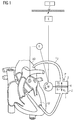
- the pulsation blood pump consists essentially of a bidirectional pumping system, which is connected via a first line L1 and a second line L2 on the one hand to a blood stream, here the aorta AO, and on the other hand to a heart chamber, here the left ventricle LV.
- the bidirectional pumping system consists essentially of a pump P and a pump P driving motor M. As the pump and / or the motor specifically procure in each case and are coupled together, is of minor importance to the invention.
- the motor M and thus the pump P is operated via a controller St according to predetermined heart rhythm alternately in one direction and the other.
- the cardiac rhythm data for controlling the pumping system eg pressure, ECG, contraction, PPS, etc.
- a sensor system S coupled to the controller St and transmitted to the controller St. This is in FIG. 1 merely indicated schematically by a lying in the atrium of the left ventricle LV sensor S, which may be a pressure sensor.
- the energy required for the operation of the pumping system can be made available from an energy store E which, for example, is charged without contact either permanently or preferably temporarily via a transmitter T.
- the piston K is now displaced according to the heart rhythm so that the volume V 1 of the pumping chamber 1 is reduced during systole and accordingly blood from the pumping chamber 1 via the line L 1 is pumped into the left ventricle LV.
- blood from the aorta AO is simultaneously sucked through the line L 2 into the increasing volume V 2 of the second pumping chamber 2.
- the left ventricle LV thereby works against a reduced aortic pressure, and also the blood volume displaced from the pumping chamber 1 flows through the left ventricle LV and the aortic valve into the aorta AO.
- the piston K is moved in the opposite direction, allowing blood from the left ventricle LV is sucked through the line L1 in the pumping chamber 1 and at the same time a corresponding amount of blood from the second pumping chamber 2 is conveyed through the line L2 into the aorta AO.
- the blood pressure in the aorta AO is increased by the blood conveyed into the aorta AO so that the blood flows reliably into the organs, including the heart, and the peripheral bloodstreams.
- the cardiac muscle wall tension can be kept low and blood supply to the heart even more efficient.
- FIG. 2 shows a first modification of this basic principle.
- the piston K is designed here as a differential piston with two piston surfaces of different sizes. Accordingly, the volumes V 1 and V 2 do not change to the same extent during a movement of the piston K in the direction R.
- due to the differential piston K a smaller amount of blood is pumped back and forth between the left ventricle LV and the pumping chamber 1 than between the aorta AO and the second pumping chamber 2.
- the larger piston surface of the differential piston can be either on the side of the heart or the bloodstream.
- the differential piston K requires on the side of the smaller piston surface an additional compliance chamber C, which is connected via a line L 3 to the pump P.
- the compliance chamber C absorbs the difference between the volume displacement V 2 and V 1 , which is positive or negative depending on the direction of displacement of the differential piston K.
- the compliance chamber C is placed in a location within the patient to which it is exposed only to a low ambient pressure, for example in the abdomen, and is over Line L 3 connected to the pump P. In the line L 3 and the compliance chamber C is preferably a liquid, so in particular no blood.
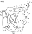
- FIG. 3 shows a second modification of the basic principle.
- the first pumping chamber 1 with a first compliance chamber C 1 forms a first double chamber
- the second pumping chamber 2 forms a second double chamber with a second compliance chamber C 2 .
- the pump chambers 1 and 2 are separated from the compliance chambers C 1 and C 2 in each case by a membrane M 1 and M 2 , so that the volume V 1 and V 2 of the pump chambers 1 and 2 is variable in each case.
- a fluid is then pumped back and forth between the compliance chambers C 1 and C 2 corresponding to the heart rhythm so that the variable volumes V 1 and V 2 of the two pumping chambers 1 and 2 in the previously with respect to FIG. 1 change the way described.
- the pump P is connected via lines L 4 and L 5 to the compliance chambers C 1 and C 2 .
- the lines L 4 , L 5 and the compliance chambers C 1 , C 2 is a hydraulic fluid, so in particular no blood.
- the pump P is thus reliably shielded from the blood circulation by means of the membrane M 1 and M 2 .
- the structure and the effectiveness of the pumps P which can be used for the pump system are thereby favored. Also, while the fatigue strength of the pumping system is significantly improved.
- An additional compliance chamber Cv may be provided to accommodate volume fluctuations when the amounts of blood V 1 and V 2 are different in size.
- FIG. 3 shows such additional compliance chamber Cv for receiving a portion of the funded between the compliance chambers C 1 and C 2 fluid.
- This additional compliance chamber Cv is optional and preferably variably adjustable with respect to its compliance properties.
- the control valve StV serves to set the compliance properties. The adjustment can be done either before or after implantation, preferably, for example, by remote control even after implantation either as needed or constantly. As a result, the blood volumes accommodated in the pumping chambers 1 and 2 can be varied, possibly also dynamically.
- One reason for such a measure may be, for example, that problems arise during the filling of one or the other of the two pumping chambers 1 and 2 or that the available volumes of the pumping chambers 1 and 2 should be deliberately varied.
- the control valve StV By means of the control valve StV, it is thus possible to variably control the intake and discharge volumes of the pumping chambers 1 and 2.
- the volume reduction must not result in so much blood constantly remaining in one of the pumping chambers that successive clumping of the blood is to be feared.
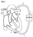
- FIG. 4 finally shows another modification of the in FIG. 1 illustrated basic principle.
- the lines L 1 and L 2 of the pulsation blood pump are not connected to the left ventricle LV and the aorta AO but instead to the right ventricle RV and the pulmonary arteries PA.
Landscapes
- Health & Medical Sciences (AREA)
- Heart & Thoracic Surgery (AREA)
- Engineering & Computer Science (AREA)
- Cardiology (AREA)
- Life Sciences & Earth Sciences (AREA)
- Anesthesiology (AREA)
- Biomedical Technology (AREA)
- Hematology (AREA)
- Mechanical Engineering (AREA)
- Animal Behavior & Ethology (AREA)
- General Health & Medical Sciences (AREA)
- Public Health (AREA)
- Veterinary Medicine (AREA)
- Vascular Medicine (AREA)
- Rheumatology (AREA)
- External Artificial Organs (AREA)
Description
- Die Erfindung betrifft eine extravasale Pulsationsblutpumpe und findet Anwendung bei der Unterstützung der Pulsation des menschlichen Herzens.
- Um es einem vorgeschädigten menschlichen Herzen zu ermöglichen, sich zu erholen, wird die Pulsation des Herzens mittels künstlicher Pumpen unterstützt. Breite Anwendung finden sogenannte intraaortale Ballonpumpen (IABP). Dazu wird ein Ballon in der Aorta platziert und von außerhalb des Körpers durch einen relativ langen Katheter hindurch abwechselnd, entsprechend dem Herzrythmus, mit Helium gefüllt und entleert. Das Entleeren erfolgt kurz vor Beginn der Systole, um auf diese Weise den Blutdruck in der Aorta signifikant zu senken, so dass das Herz sein Blutvolumen gegen einen geringen Aortendruck in die Aorta ausstoßen kann. Am Anfang der Diastole wird der Ballon wieder gefüllt, erhöht dadurch den Druck in der Aorta und treibt so das Blut in die Organe und peripheren Blutbahnen. Dieses Verfahren ist auch als aortale Gegenpulsation bzw. Counterpulsation-Verfahren bekannt.
- In
US 2005/0096496 A1 werden verschiedene Nachteile von intraaortalen Ballonpumpen herausgestellt. Unter anderem sind sie wegen des ständig liegenden Katheters infektionsbehaftet und erlauben es dem Patienten nicht, das Bett zu verlassen. Daher werden sie in der Regel nur über ein oder zwei Tage eingesetzt, obwohl chronisch schwache Herzen eine langfristige Unterstützung benötigen würden. Außerdem behindert der Katheter in der Blutbahn den Blutfluss. Es wird dort daher vorgeschlagen, eine subkutan implantierte Pumpe über eine Leitung an eine arterielle Blutbahn anzuschließen und Blut aus der Arterie abzusaugen, wenn das Herz kontrahiert (Systole), und wieder in die Arterie zurückzupumpen, wenn das Herz erschlafft (Diastole). Auf diese Weise wird eine Gegenpulsation erreicht, ohne dass ein Ballon die Blutbahn selbst verschließt oder ein Katheter innerhalb der Blutbahn verläuft. Die Pumpe kann als Blase, Sack oder Diaphragmapumpe ausgebildet sein. Es wird auch vorgeschlagen, die extravasale Gegenpulsationspumpe durch eine zweite extravasale Pumpe zu ergänzen, mit der Blut kontinuierlich über eine erste Leitung direkt aus dem Herzen abgesaugt und über eine zweite Leitung unmittelbar derjenigen Arterie zugeführt wird, an die auch die extravasale Gegenpulsationspumpe angeschlossen ist. - Mit extravasalen Gegenpulsationsblutpumpen sind wesentlich höhere Volumenströme erzielbar als mit herkömmlichen aortalen Ballonpumpen, nämlich bis zu 2,4 l pro Minute anstelle von 0,71 pro Minute. Derartige Gegenpulsationssysteme lassen sich darüber hinaus durch Copulsationssysteme ersetzen oder ergänzen, bei denen die Leitung der extravasalen Blutpumpe unmittelbar mit einem Ventrikel des Herzens verbunden wird. Die Pumpe saugt dann während der Diastole temporär Blut aus dem Ventrikel in eine Kammer, um so das Blutvolumen im Ventrikel klein zu halten und ein Dilatieren des Herzens zu verhindern, und pumpt dieses Blut während der anschließenden Systole in den Ventrikel zurück, von wo aus es durch die geöffnete Herzklappe in die arterielle Blutbahn strömt.
- Sowohl die Gegenpulsation als auch die Copulsation mittels einer im Körper vollimplantierten extravasalen Blutpumpe besitzen das Problem, dass das mittels der Pumpe abgesaugte Blut in einem Speicher zwischengespeichert werden muss. Dazu besitzt die Blutpumpe eine sogenannte ComplianceKammer deren Volumen sich beim Füllen der Blutpumpe entsprechend verringert. Compliance-Kammern sind relativ voluminös. Dies gilt insbesondere für gasgefüllte Compliance-Kammern, weil die Pumpe bei einer kleinen gasgefüllten Compliance-Kammer viel Energie benötigen würde, um das Gasvolumen der Compliance-Kammer während der Ansaugphase entsprechend zu komprimieren. Dieses Problem verdoppelt sich, wenn sowohl eine Gegenpulsationspumpe als auch eine Copulsationspumpe gleichzeitig implantiert werden.
-
US 2010/0268333 A1 beschreibt verschiedene Systeme und Verfahren zur Steuerung von Blutpumpen, wobei einzelne der dort beschriebenen Blutpumpen bauartbedingt auch rückwärts betrieben werden können und insofern als bidirektionales Pumpsystem bezeichnet werden können. Es wird dort vorgeschlagen, die beschriebenen Pumpen zur Herzunterstützung als eine Art Bypass zwischen dem linken Ventrikel und der aufsteigenden oder absteigenden Aorta einzusetzen und das Blut an der Aortenklappe vorbei unmittelbar vom linken Ventrikel in die Aorta zu fördern. Dies kann wiederum im Copulsationsmodus erfolgen, also während der Kontraktionsphase des Herzens (Systole), indem die Pumpe den Großteil oder den gesamten Blutfluss übernimmt, während der Ventrikel nur mit jedem vierten oder fünften Herzschlag durch die Aortenklappe fördert, um einen Strömungsstillstand an der Aortenwurzel zu vermeiden, der ansonsten zu Thrombosekomplikationen führen könnte. Alternativ kann das Blut während der Erschlaffungsphase des Herzens (Diastole) vom linken Ventrikel in die Aorta gepumpt werden, nämlich im so genannten Gegenpulsationsmodus, bei dem ein wesentlicher Teil des Blutes nach wie vor vom Ventrikel durch die Aortenklappe in die Aorta gefördert wird. - Aufgabe der vorliegenden Erfindung ist es, die Unterstützung der Pulsation des Herzens mittels extravasaler Pulsationsblutpumpen zu verbessern und insbesondere eine Pulsationsblutpumpe vorzuschlagen, die hinsichtlich ihrer Funktionalität und Baugröße im Vergleich zu den vorbeschriebenen extravasalen Pulsationsblutpumpen optimiert ist.
- Diese Aufgabe wird durch eine Pulsationsblutpumpe mit den Merkmalen des Anspruchs 1 gelöst. In davon abhängigen Ansprüchen sind vorteilhafte Ausgestaltungen und Weiterbildungen der Erfindung angegeben.
- Die erfindungsgemäße Pulsationsblutpumpe kombiniert die Funktionen der Gegenpulsation und Copulsation und besitzt zu diesem Zweck ein bidirektional wirkendes Pumpsystem, welches über zwei Leitungen einerseits mit einer Blutbahn, zum Beispiel der Aorta, und andererseits mit einer Herzkammer, zum Beispiel dem linken Ventrikel, verbunden ist. Zwischen dem Herz und der Blutbahn liegt ein Ventil, welches normalerweise durch eine Herzklappe gebildet wird. Das bidirektionale Pumpsystem ist dazu eingerichtet, während der Diastole des Herzens eine erste Menge Blut aus dem Herzen zu entnehmen und im Wesentlichen gleichzeitig eine zweite Menge Blut in die Blutbahn einzubringen. Andererseits ist das Pumpsystem dazu eingerichtet, während der auf die Diastole folgenden Systole des Herzens eine der zweiten Menge entsprechende Menge Blut aus der Blutbahn wieder zu entnehmen und im Wesentlichen gleichzeitig wiederum eine der ersten Menge entsprechende Menge Blut in das Herz einzubringen. Die ersten und zweiten Mengen können identisch sein, aber das ist nicht zwingend, denn das Pumpsystem kann als Differentialpumpsystem ausgebildet sein.
- Im Ergebnis wird das Herz sowohl während der Systole als auch während der Diastole deutlich entlastet. Denn während der Systole fördert das Herz gegen einen geringeren arteriellen Druck, weil der Blutbahn, in die das Herz fördert, gleichzeitig Blut entnommen wird. Während der anschließenden Diastole wird das Herz dadurch entlastet, dass ein Teil des Füllvolumens mittels der Blutpumpe aus der betreffenden Herzkammer entnommen und erst während der darauf folgenden Systole wieder in die Herzkammer eingebracht wird. Die Herzkammer dehnt sich somit weniger aus, so dass ein Dilatieren oder Aufweiten der Herzkammer verhindert oder verringert wird. Selbst wenn sich die Herzkammer während der Diastole bis auf ihr normales Maß weitet und mit Blut füllt, so wird mittels der erfindungsgemäßen Pulsationsblutpumpe zumindest erreicht, dass sich das Füllvolumen der betreffenden Herzkammer um die Menge des mittels des bidirektionalen Pumpsystems aus der Herzkammer entnommenen Bluts "vergrößert", weil eben diese Menge während der nachfolgenden Systole wieder in die Herzkammer zurückgeführt wird und diese Menge an Blut zeitgleich zur Herzaktivität in das anschließende Gefäßsystem ausgeworfen wird. Während auf diese Weise das Herz während der Diastole entlastet und/oder kapazitiv erweitert wird, wird der Druck in der zugehörigen Blutbahn, beispielsweise der Aorta, aufgrund der gleichzeitig in die Blutbahn eingebrachten Blutmenge erhöht, so dass aufgrund des erhöhten Blutdrucks in der betreffenden Blutbahn die Organe und angrenzenden Blutgefäße vermehrt mit Blut versorgt werden. Die erfindungsgemäße Pulsationsblutpumpe mit bidirektional wirkendem Pumpsystem kombiniert somit die Funktionen und Vorteile einer copulsierenden extravasalen Blutpumpe mit denen einer gegenpulsierenden extravasalen Blutpumpe.
- Ein wesentlicher weiterer Vorteil der erfindungsgemäßen Pulsationsblutpumpe besteht aber darin, dass es nicht notwendig ist, für jede dieser beiden Funktionen eine separate Compliance-Kammer vorzusehen. Statt dessen kann das Pumpsystem beispielsweise eine erste Pumpkammer mit variablem Volumen aufweisen, die zum Beispiel an die Herzkammer angeschlossen ist, und eine zweite Pumpkammer mit variablem Volumen, die dann an die entsprechende Blutbahn angeschlossen ist, wobei die beiden Pumpkammern so miteinander gekoppelt sind, dass in dem Maße, wie Blut in die erste Pumpkammer angesaugt wird, Blut aus der zweiten Pumpkammer ausgestoßen wird, und umgekehrt. Dementsprechend wirken die beiden Pumpkammern für die jeweils andere Pumpkammer als Compliance-Kammer. Dies lässt sich anschaulich mit einem zweiseitig wirkenden Zylinderkolben vergleichen. Während durch Verlagerung des Kolbens innerhalb eines Zylinders das Volumen in Bewegungsrichtung vor dem Kolben verringert wird, vergrößert sich das Volumen hinter dem Kolben. Das sich verringernde Volumen vor dem Kolben ist vergleichbar mit einer Compliance-Kammer für das sich vergrößernde Volumen hinter dem Kolben. Bei umgekehrter Bewegungsrichtung des Kolbens dreht sich diese Funktionalität entsprechend um. Das heißt, die unter Druck stehende Kammer des Kolbenzylinders wirkt immer gleichzeitig als Pumpkammer, aus der heraus gefördert wird, und als Compliance-Kammer für die auf der anderen Seite des Kolbens liegende Kammer.
- Dieses grundlegende Prinzip lässt sich in verschiedener Weise abwandeln. Insbesondere lässt sich mittels eines Differentialkolbens ein Differentialpumpsystem realisieren, welches unterschiedliche Volumenströme in die eine und die andere Richtung fördert - bei absolut betrachtet gleicher Kolbenwegstrecke.
- Erfindungsgemäß helfen die jeweiligen Drücke auf der Saugseite der Pumpe, die erforderliche Energie zur Verschiebung des Kolbens oder der hydraulischen Flüssigkeit gering zu halten. Dies ist besonders für ein voll implantierbares System entscheidend, um die Batteriegröße gering zu halten.
- Eine andere Abwandlung des vorbeschriebenen grundlegenden Prinzips sieht separate Compliance-Kammern vor. Das heißt, während bei dem vorbeschriebenen zweiseitig wirkenden Zylinderkolben das Volumen auf einer Seite des Kolbens gleichzeitig als Pumpkammer und als ComplianceKammer wirkt, sind diese beiden Funktionen bei dieser abgewandelten Ausführungsform voneinander getrennt. So kann das bidirektionale Pumpsystem eine erste Pumpkammer mit variablem Volumen und eine erste Compliance-Kammer mit variablem Volumen besitzen, die gemeinsam eine erste Doppelkammer bilden, und eine zweite Pumpkammer mit variablem Volumen kann mit einer zweiten Compliance-Kammer mit variablem Volumen gemeinsam eine zweite Doppelkammer bilden. Dabei sind die Compliance-Kammern von der jeweils zugehörigen Pumpkammer durch eine variable Trennwand getrennt, die beispielsweise als flexible Membran ausgebildet sein oder zumindest eine flexible Membran umfassen kann. Mittels einer Pumpe wird nun ein Fluid zwischen den beiden Compliance-Kammern hinund hergefördert, so dass je nach Förderrichtung aus der einen zugehörigen Pumpkammer Blut ausgestoßen wird, während gleichzeitig in die andere zugehörige Pumpkammer Blut angesaugt wird, und umgekehrt.
- Der Vorteil dieser letztgenannten Abwandlung des grundlegenden Prinzips besteht gegenüber herkömmlichen Systemen vor allem darin, dass die Compliance-Kammern statt mit einem Gas mit einer Flüssigkeit gefüllt sein können, so dass die Compliance-Kammern nicht größer sein müssen als das von den Pumpkammern aufzunehmende Blutvolumen. Dadurch ist das System besonders effizient und darüberhinaus sicherer im Vergleich zu gasgefüllten Compliance-Kammern. Als Flüssigkeit bietet sich jede Flüssigkeit an. Ein weiterer Vorteil dieser Abwandlung gegenüber dem zweiseitig wirkenden Zylinderkolben liegt darin, dass die Pumpe vom Blut entkoppelt ist, das heißt die Pumpe fördert nur Flüssigkeit zwischen den beiden Compliance-Kammern, und kein Blut.
- Die erfindungsgemäße Pulsationsblutpumpe kann vollständig in den Körper eines Patienten implantiert werden. Zumindest aber das Pumpsystem ist dazu vorgesehen und eingerichtet, implantiert zu werden. Eine Energieversorgung für die Pumpe oder, falls die Pumpe mittels eines separaten Motors angetrieben wird, für diesen Motor, kann ebenfalls implantierbar sein und beispielsweise transkutan entweder kontaktbehaftet oder vorzugsweise kontaktlos von Zeit zu Zeit oder kontinuierlich aufgeladen werden.
- Selbstverständlich umfasst die erfindungsgemäße Pulsationsblutpumpe eine Steuerung, die vorgesehen und dazu eingerichtet ist, das bidirektionale Pumpsystem entsprechend einem vorgegebenen Herzrhythmus abwechselnd in die eine und die andere Richtung zu betreiben. Der Herzrhythmus kann in unterschiedlicher Weise mittels geeigneter Sensorik erfasst und die so ermittelten Herzrhythmusdaten an die Steuerung übermittelt werden. Insbesondere kann die Pulsationsblutpumpe mittels derselben Herzrhythmusdaten gesteuert werden, die auch zur Steuerung herkömmlicher synchroner Herzunterstützungssysteme, wie z.B. intraaortaler Blutpumpen, verwendet werden.
- Nachfolgend wird die Erfindung anhand der begleitenden Zeichnungen beispielhaft erläutert. Darin zeigen:
- Figur 1
- das grundsätzliche Prinzip einer erfindungsgemäßen Pulsationsblutpumpe am Beispiel der Unterstützung des linken Ventrikels,
- Figur 2
- eine erste Abwandlung des grundsätzlichen Prinzips,
- Figur 3
- eine zweite Abwandlung des grundsätzlichen Prinzips und
- Figur 4
- das grundsätzliche Prinzip am Beispiel der Unterstützung des rechten Ventrikels.
- Anhand der schematischen Darstellung gemäß
Figur 1 wird nachfolgend das grundsätzliche Prinzip der erfindungsgemäßen Pulsationsblutpumpe erläutert. Die Pulsationsblutpumpe besteht im Wesentlichen aus einem bidirektionalen Pumpsystem, welches über eine erste Leitung L1 und eine zweite Leitung L2 einerseits mit einer Blutbahn, hier der Aorta AO, und andererseits mit einer Herzkammer, hier dem linken Ventrikel LV, verbunden ist. Das bidirektionale Pumpsystem besteht im Wesentlichen aus einer Pumpe P und einem die Pumpe P antreibenden Motor M. Wie die Pumpe und/oder der Motor im Einzelfall konkret beschaffen und miteinander gekoppelt sind, ist für die Erfindung von untergeordneter Bedeutung. Wesentlich für das in Figur 1 dargestellte grundlegende Prinzip ist, dass die Pumpe P nach Art einer zweiseitig wirkenden Kolben-Zylinder-Anordnung ausgebildet ist, bei der der Kolben K innerhalb eines Zylinders Z in einer Richtung hin und zurück bewegt wird. Dadurch ändern sich die Volumina V1 und V2 in den einander gegenüberliegenden, durch den Kolben K getrennten Pumpkammern 1 und 2. - Der Motor M und damit die Pumpe P wird über eine Steuerung St entsprechend vorgegebenen Herzrythmus abwechselnd in die eine und die andere Richtung betrieben. Die Herzrythmusdaten zur Steuerung des Pumpsystems (z.B. Druck, EKG, Kontraktion, PPS, etc.) können mittels einer mit der Steuerung St gekoppelten Sensorik S erfasst und an die Steuerung St übermittelt werden. Dies ist in
Figur 1 lediglich schematisch angedeutet durch einen im Vorhof des linken Ventrikel LV liegenden Sensor S, der ein Drucksensor sein kann. - Die für den Betrieb des Pumpsystems notwendige Energie kann aus einem Energiespeicher E zur Verfügung gestellt werden, der beispielsweise kontaktlos entweder ständig oder vorzugsweise zeitweise über einen Transmitter T entsprechend aufgeladen wird.
- Unter Verwendung dieser Energie und unter Berücksichtigung der von der Steuerung St verarbeiteten Herzrythmusdaten wird nun der Kolben K entsprechend dem Herzrythmus so verlagert, dass während der Systole das Volumen V1 der Pumpkammer 1 verringert wird und dementsprechend Blut aus der Pumpkammer 1 über die Leitung L1 in den linken Ventrikel LV gepumpt wird. Dadurch wird gleichzeitig Blut aus der Aorta AO durch die Leitung L2 hindurch in das sich vergrößernde Volumen V2 der zweiten Pumpkammer 2 angesaugt. Der linke Ventrikel LV arbeitet dadurch gegen einen verringerten Aortendruck, und auch das aus der Pumpkammer 1 verdrängte Blutvolumen fließt durch den linken Ventrikel LV und die Aortenklappe in die Aorta AO. Während der nachfolgenden Diastole wird der Kolben K in die entgegengesetzte Richtung bewegt, so dass Blut aus dem linken Ventrikel LV durch die Leitung L1 in die Pumpkammer 1 gesaugt und gleichzeitig eine entsprechende Menge Blut aus der zweiten Pumpkammer 2 durch die Leitung L2 in die Aorta AO gefördert wird. Dadurch wird die Dehnung des linken Ventrikels LV gering gehalten und einem Dilatieren des Herzens entgegengewirkt, so dass sich das Herz erholen kann. Gleichzeitig wird durch das in die Aorta AO geförderte Blut der Blutdruck in der Aorta AO so erhöht, dass das Blut zuverlässig in die Organe, also auch in das Herz, und die peripheren Blutbahnen fließt. Durch Verringerung der diastolischen Ventrikelgröße kann die Wandspannung des Herzmuskels gering gehalten werden und so die Blutversorgung des Herzens noch effizienter erfolgen.
-
Figur 2 zeigt eine erste Abwandlung dieses grundlegenden Prinzips. Der Kolben K ist hier als Differentialkolben mit zwei unterschiedlich großen Kolbenflächen ausgebildet. Dementsprechend verändern sich die Volumina V1 und V2 bei einer Bewegung des Kolbens K in Richtung R nicht im selben Maße. In dem konkret dargestellten Ausführungsbeispiel wird aufgrund des Differentialkolbens K eine geringere Menge Blut zwischen dem linken Ventrikel LV und der Pumpkammer 1 hin und her gefördert als zwischen der Aorta AO und der zweiten Pumpkammer 2. Je nach dem, welche Herzfunktion mit der Pulsationsblutpumpe verstärkt unterstützt werden soll, kann die größere Kolbenfläche des Differentialkolben entweder auf der Seite des Herzens oder der Blutbahn liegen. Der Differentialkolben K benötigt allerdings auf der Seite der kleineren Kolbenfläche eine zusätzliche Compliancekammer C, welche über eine Leitung L3 mit der Pumpe P verbunden ist. Die Compliancekammer C nimmt die Differenz aus der Volumenverschiebung V2 und V1 auf, die je nach Verschieberichtung des Differentialkolbens K positiv oder negativ ist. Die Compliancekammer C wird an einem Ort innerhalb des Patienten platziert, an welchem sie nur einem geringen Umgebungsdruck ausgesetzt ist, beispielsweise im Abdomen, und ist über eine Leitung L3 mit der Pumpe P verbunden. In der Leitung L3 und der Compliance-Kammer C befindet sich vorzugsweise eine Flüssigkeit, also insbesondere kein Blut. -
Figur 3 zeigt eine zweite Abwandlung des grundlegenden Prinzips. Hier bildet die erste Pumpkammer 1 mit einer ersten Compliance-Kammer C1 eine erste Doppelkammer und die zweite Pumpkammer 2 mit einer zweiten Compliance-Kammer C2 eine zweite Doppelkammer. Die Pumpkammern 1 und 2 sind von den Compliance-Kammern C1 und C2 jeweils durch eine Membran M1 und M2 getrennt, so dass das Volumen V1 und V2 der Pumpkammern 1 und 2 jeweils variabel ist. Mittels einer Pumpe P, die hier nur schematisch wiedergegeben ist und beispielhaft eine bidirektionale Rotationspumpe sein kann, wird dann ein Fluid zwischen den Compliance-Kammern C1 und C2 entsprechend dem Herzrythmus so hin- und hergepumpt, dass sich die variablen Volumen V1 und V2 der beiden Pumpkammern 1 und 2 in der zuvor in Bezug aufFigur 1 beschriebenen Weise verändern. Dazu ist die Pumpe P über die Leitungen L4 und L5 mit den Compliance-Kammern C1 und C2 verbunden. In den Leitungen L4, L5 und den Compliance-Kammern C1, C2 befindet sich ein Hydraulikfluid, also insbesondere kein Blut. Die Pumpe P ist somit vom Blutkreislauf mittels der Membrane M1 und M2 zuverlässig abgeschirmt. Der Aufbau und die Effektivität der für das Pumpsystem einsetzbaren Pumpen P ist dadurch begünstigt. Ebenfalls wird dabei die Dauerfestigkeit des Pumpsystems erheblich verbessert. - Eine zusätzliche Compliance-Kammer Cv kann vorgesehen sein, um Volumenschwankungen aufzunehmen, wenn die Blutmengen V1 und V2 unterschiedlich groß ausfallen.
Figur 3 zeigt eine solche zusätzliche ComplianceKammer Cv zur Aufnahme eines Teils des zwischen den Compliance-Kammern C1 und C2 geförderten Fluids. Diese zusätzliche ComplianceKammer Cv ist optional und vorzugsweise bezüglich seiner Compliance-Eigenschaften variabel einstellbar. Zum Einstellen der Compliance-Eigenschaften dient das Steuerventil StV. Die Einstellung kann entweder vor der Implantation oder vorzugsweise zum Beispiel per Remote-Control auch nach der Implantation entweder bedarfsweise oder ständig erfolgen. Dadurch lassen sich die in den Pumpkammern 1 und 2 aufgenommenen Blutvolumina variieren, gegebenenfalls auch dynamisch. Ein Grund für eine solche Maßnahme kann beispielsweise darin liegen, dass sich beim Füllen der einen oder anderen der beiden Pumpkammern 1 und 2 Probleme ergeben oder dass die verfügbaren Volumina der Pumpkammern 1 und 2 absichtlich variiert werden sollen. So ist es möglich, dass trotz der den beiden Pumpkammern 1 und 2 gemeinsamen Pumpe P unterschiedliche Volumina zwischen den zugehörigen Compliance-Kammern C1 und C2 gefördert werden, wobei das Differenzvolumen von der zusätzlichen Compliance-Kammer Cv aufgenommen wird. Mittels des Steuerventils StV ist es somit möglich, die Ansaug- und Auswurfvolumina der Pumpkammern 1 und 2 variabel zu steuern. Die Volumenreduzierung darf allerdings nicht dazu führen, dass in einer der Pumpkammern ständig so viel Blut verbleibt, dass sukzessive ein Verklumpen des Bluts zu befürchten ist. - Anstatt die zusätzliche Compliance-Kammer Cv an die Leitung L5 anzuschließen, kann sie auch an die Leitung L4 angeschlossen werden.
-
Figur 4 zeigt schließlich noch eine weitere Abwandlung des inFigur 1 dargestellten grundlegenden Prinzips. Hier sind die Leitungen L1 und L2 der Pulsationsblutpumpe nicht mit dem linken Ventrikel LV und der Aorta AO sondern stattdessen mit dem rechten Ventrikel RV und den Pulmonalarterien PA verbunden. - Es besteht auch die Möglichkeit, zwei getrennte Pulsationsblutpumpen der vorbeschriebenen Art einerseits für die linke Herzhälfte und andererseits für die rechte Herzhälfte gleichzeitig zu betreiben.
Claims (8)
- Extravasale Pulsationsblutpumpe, umfassend- eine erste Leitung (L1) zur Verbindung der Pulsationsblutpumpe an eine Herzkammer (LV; RV),- eine zweite Leitung (L2) zur Verbindung der Pulsationsblutpumpe an eine Blutbahn (AO; PA) und- ein bidirektionales Pumpsystem (P; P, M),dadurch gekennzeichnet, dass das bidirektionale Pumpsystem dazu eingerichtet ist, abwechselnd einerseits Blut durch die erste Leitung (L1) anzusaugen und gleichzeitig Blut durch die zweite Leitung (L2) auszustoßen und andererseits Blut durch die zweite Leitung (L2) anzusaugen und gleichzeitig Blut durch die erste Leitung (L1) auszustoßen, wobei eine Steuerung (St) vorgesehen ist, das Pumpsystem (P; P, M) entsprechend einem vorgegebenen Herzrhythmus abwechselnd in die eine und die andere Richtung (R) zu betreiben.
- Pulsationsblutpumpe nach Anspruch 1, umfassend eine mit der Steuerung (St) gekoppelte Sensorik (S) zum Erfassen und Übermitteln von Herzrhythmusdaten an die Steuerung (St).
- Pulsationsblutpumpe nach Anspruch 1 oder 2, wobei das Pumpsystem (P; P, M) eine erste Pumpkammer (1) mit variablem Volumen (V1), die an die erste Leitung (L1) angeschlossen ist, und eine zweite Pumpkammer (2) mit variablem Volumen (V2), die an die zweite Leitung (L2) angeschlossen ist, aufweist, wobei die erste und zweite Pumpkammer (1, 2) so miteinander gekoppelt sind, dass, wenn Blut durch die erste Leitung (L1) in die erste Pumpkammer (1) gesaugt wird, Blut von der zweiten Pumpkammer (2) in die zweite Leitung (L2) ausgestoßen wird, und umgekehrt.
- Pulsationsblutpumpe nach Anspruch 3, wobei die erste Pumpkammer (1) mit einer ersten Compliancekammer (C1) mit variablem Volumen eine erste Doppelkammer und die zweite Pumpkammer (2) mit einer zweiten Compliancekammer (C2) mit variablem Volumen eine zweite Doppelkammer bilden, wobei die erste Pumpkammer (1) von der ersten Compliancekammer (C1) und die zweite Pumpkammer (2) von der zweiten Compliancekammer (C2) jeweils durch eine variable Trennwand (M1, M2) getrennt sind, und wobei das Pumpsystem eine Pumpe (P) umfasst, die dazu eingereicht ist, ein Fluid zwischen der ersten Compliancekammer (C1) und der zweiten Compliancekammer (C2) hin und her zu fördern.
- Pulsationsblutpumpe nach Anspruch 4, wobei die Trennwände (M1, M2) jeweils eine flexible Membran umfassen.
- Pulsationsblutpumpe nach einem der Ansprüche 4 oder 5, wobei das Fluid eine Flüssigkeit ist.
- Pulsationspumpe nach einem der Ansprüche 1 bis 6, wobei das Pumpsystem ein Differentialpumpsystem ist.
- Pulsationsblutpumpe nach einem der Ansprüche 1 bis 7, wobei das Pumpsystem (P; P, M) eingerichtet ist, in den Körper eines Patienten implantiert zu werden.
Applications Claiming Priority (2)
| Application Number | Priority Date | Filing Date | Title |
|---|---|---|---|
| DE102012207042.7A DE102012207042B4 (de) | 2012-04-27 | 2012-04-27 | Pulsationsblutpumpe |
| PCT/EP2013/058648 WO2013160411A1 (de) | 2012-04-27 | 2013-04-25 | Pulsationsblutpumpe |
Publications (2)
| Publication Number | Publication Date |
|---|---|
| EP2841123A1 EP2841123A1 (de) | 2015-03-04 |
| EP2841123B1 true EP2841123B1 (de) | 2016-07-06 |
Family
ID=48227262
Family Applications (1)
| Application Number | Title | Priority Date | Filing Date |
|---|---|---|---|
| EP13719515.2A Active EP2841123B1 (de) | 2012-04-27 | 2013-04-25 | Pulsationsblutpumpe |
Country Status (7)
| Country | Link |
|---|---|
| US (1) | US9555173B2 (de) |
| EP (1) | EP2841123B1 (de) |
| JP (1) | JP6058787B2 (de) |
| KR (1) | KR101926847B1 (de) |
| AU (1) | AU2013254650B2 (de) |
| DE (1) | DE102012207042B4 (de) |
| WO (1) | WO2013160411A1 (de) |
Families Citing this family (51)
| Publication number | Priority date | Publication date | Assignee | Title |
|---|---|---|---|---|
| EP3634528B1 (de) | 2017-06-07 | 2023-06-07 | Shifamed Holdings, LLC | Intravaskuläre fluidbewegungsvorrichtungen, systeme und verwendungsverfahren |
| US11511103B2 (en) | 2017-11-13 | 2022-11-29 | Shifamed Holdings, Llc | Intravascular fluid movement devices, systems, and methods of use |
| DE102018201030B4 (de) | 2018-01-24 | 2025-10-16 | Kardion Gmbh | Magnetkuppelelement mit magnetischer Lagerungsfunktion |
| EP3746149B1 (de) | 2018-02-01 | 2025-08-06 | Shifamed Holdings, LLC | Intravaskuläre blutpumpen |
| EP3536955A1 (de) | 2018-03-08 | 2019-09-11 | Berlin Heart GmbH | Antriebsvorrichtung für eine membranfluidpumpe und betriebsverfahren |
| DE102018207575A1 (de) | 2018-05-16 | 2019-11-21 | Kardion Gmbh | Magnetische Stirndreh-Kupplung zur Übertragung von Drehmomenten |
| DE102018207611A1 (de) | 2018-05-16 | 2019-11-21 | Kardion Gmbh | Rotorlagerungssystem |
| DE102018207594A1 (de) | 2018-05-16 | 2019-11-21 | Kardion Gmbh | Rotor, Magnetkupplungsvorrichtung, Elektromotor für ein Herzunterstützungssystem, Pumpeneinheit für ein Herzunterstützungssystem sowie Verfahren zum Herstellen eines Rotors |
| DE102018208549A1 (de) | 2018-05-30 | 2019-12-05 | Kardion Gmbh | Elektronikmodul für ein Herzunterstützungssystem und Verfahren zum Herstellen eines Elektronikmoduls für ein Herzunterstützungssystem |
| DE102018208539A1 (de) | 2018-05-30 | 2019-12-05 | Kardion Gmbh | Motorgehäusemodul zum Abdichten eines Motorraums eines Motors eines Herzunterstützungssystems und Herzunterstützungssystem und Verfahren zum Montieren eines Herzunterstützungssystems |
| DE102018208538A1 (de) | 2018-05-30 | 2019-12-05 | Kardion Gmbh | Intravasale Blutpumpe und Verfahren zur Herstellung von elektrischen Leiterbahnen |
| DE102018208541A1 (de) | 2018-05-30 | 2019-12-05 | Kardion Gmbh | Axialpumpe für ein Herzunterstützungssystem und Verfahren zum Herstellen einer Axialpumpe für ein Herzunterstützungssystem |
| DE102018208550A1 (de) | 2018-05-30 | 2019-12-05 | Kardion Gmbh | Leitungsvorrichtung zum Leiten eines Blutstroms für ein Herzunterstützungssystem, Herzunterstützungssystem und Verfahren zum Herstellen einer Leitungsvorrichtung |
| DE102018208870A1 (de) | 2018-06-06 | 2019-12-12 | Kardion Gmbh | Verfahren zur Bestimmung eines Fluid-Volumenstroms durch ein implantiertes, vaskuläres Unterstützungssystem |
| DE102018208913A1 (de) | 2018-06-06 | 2019-12-12 | Kardion Gmbh | Verfahren zum Betreiben eines implantierten, ventrikulären Unterstützungssystems |
| DE102018208933A1 (de) | 2018-06-06 | 2019-12-12 | Kardion Gmbh | Verfahren zur Bestimmung einer Strömungsgeschwindigkeit eines durch ein implantiertes, vaskuläres Unterstützungssystem strömenden Fluids |
| DE102018208936A1 (de) | 2018-06-06 | 2019-12-12 | Kardion Gmbh | Bestimmvorrichtung und Verfahren zum Bestimmen einer Viskosität eines Fluids |
| DE102018208899A1 (de) | 2018-06-06 | 2019-12-12 | Kardion Gmbh | Verfahren zum Ermitteln der Schallgeschwindigkeit in einem Fluid im Bereich eines implantierten, vaskulären Unterstützungssystems |
| DE102018208879A1 (de) | 2018-06-06 | 2020-01-30 | Kardion Gmbh | Verfahren zur Bestimmung eines Fluid-Gesamtvolumenstroms im Bereich eines implantierten, vaskuläres Unterstützungssystems |
| DE102018208931A1 (de) | 2018-06-06 | 2019-12-12 | Kardion Gmbh | Vorrichtung zum Bestimmen eines Herzzeitvolumens für ein Herzunterstützungssystem, Herzunterstützungssystem und Verfahren zum Bestimmen eines Herzzeitvolumens |
| DE102018208929A1 (de) | 2018-06-06 | 2019-12-12 | Kardion Gmbh | Verfahren zur Bestimmung einer Strömungsgeschwindigkeit eines durch ein implantiertes, vaskuläres Unterstützungssystem strömenden Fluids |
| DE102018208892A1 (de) | 2018-06-06 | 2019-12-12 | Kardion Gmbh | Sensorkopfvorrichtung für ein minimalinvasives Herzunterstützungssystem und Verfahren zum Herstellen einer Sensorkopfvorrichtung für ein Herzunterstützungssystem |
| DE102018208945A1 (de) | 2018-06-06 | 2019-12-12 | Kardion Gmbh | Analysevorrichtung und Verfahren zum Analysieren einer Viskosität eines Fluids |
| DE102018208862A1 (de) | 2018-06-06 | 2019-12-12 | Kardion Gmbh | Implantierbares, vaskuläres Unterstützungssystem |
| DE102018210058A1 (de) | 2018-06-21 | 2019-12-24 | Kardion Gmbh | Statorschaufelvorrichtung zur Strömungsführung eines aus einer Austrittsöffnung eines Herzunterstützungssystems ausströmenden Fluids, Herzunterstützungssystem mit Statorschaufelvorrichtung, Verfahren zum Betreiben einer Statorschaufelvorrichtung und Herstellverfahren |
| DE102018210076A1 (de) | 2018-06-21 | 2019-12-24 | Kardion Gmbh | Verfahren und Vorrichtung zum Erkennen eines Verschleißzustands eines Herzunterstützungssystems, Verfahren und Vorrichtung zum Betreiben eines Herzunterstützungssystems und Herzunterstützungssystem |
| DE102018211297A1 (de) | 2018-07-09 | 2020-01-09 | Kardion Gmbh | Herzunterstützungssystem und Verfahren zur Überwachung der Integrität einer Haltestruktur eines Herzunterstützungssystems |
| DE102018211328A1 (de) | 2018-07-10 | 2020-01-16 | Kardion Gmbh | Laufradgehäuse für ein implantierbares, vaskuläres Unterstützungssystem |
| DE102018211327A1 (de) | 2018-07-10 | 2020-01-16 | Kardion Gmbh | Laufrad für ein implantierbares, vaskuläres Unterstützungssystem |
| DE102018212153A1 (de) | 2018-07-20 | 2020-01-23 | Kardion Gmbh | Zulaufleitung für eine Pumpeneinheit eines Herzunterstützungssystems, Herzunterstützungssystem und Verfahren zum Herstellen einer Zulaufleitung für eine Pumpeneinheit eines Herzunterstützungssystems |
| WO2020028537A1 (en) | 2018-07-31 | 2020-02-06 | Shifamed Holdings, Llc | Intravascaular blood pumps and methods of use |
| ES3055124T3 (en) | 2018-08-07 | 2026-02-10 | Kardion Gmbh | Bearing device for a heart support system, and method for rinsing a space in a bearing device for a heart support system |
| DE102018213350A1 (de) | 2018-08-08 | 2020-02-13 | Kardion Gmbh | Vorrichtung und Verfahren zur Überwachung eines Gesundheitszustands des Patienten |
| WO2020073047A1 (en) | 2018-10-05 | 2020-04-09 | Shifamed Holdings, Llc | Intravascular blood pumps and methods of use |
| JP7605482B2 (ja) | 2019-03-08 | 2024-12-24 | サマコア, インコーポレイテッド | 容積形シャトルポンプ心臓およびvad |
| WO2021011473A1 (en) | 2019-07-12 | 2021-01-21 | Shifamed Holdings, Llc | Intravascular blood pumps and methods of manufacture and use |
| US11654275B2 (en) | 2019-07-22 | 2023-05-23 | Shifamed Holdings, Llc | Intravascular blood pumps with struts and methods of use and manufacture |
| US12465748B2 (en) | 2019-08-07 | 2025-11-11 | Supira Medical, Inc. | Catheter blood pumps and collapsible pump housings |
| EP4501393A3 (de) | 2019-09-25 | 2025-04-09 | Shifamed Holdings, LLC | Katheterblutpumpen und zusammenklappbare pumpengehäuse |
| WO2021062260A1 (en) | 2019-09-25 | 2021-04-01 | Shifamed Holdings, Llc | Catheter blood pumps and collapsible blood conduits |
| US11724089B2 (en) | 2019-09-25 | 2023-08-15 | Shifamed Holdings, Llc | Intravascular blood pump systems and methods of use and control thereof |
| US11839708B2 (en) | 2019-10-19 | 2023-12-12 | SummaCor, Inc. | Linear cardiac assist pulsatile pump |
| EP4072650A4 (de) | 2019-12-11 | 2024-01-10 | Shifamed Holdings, LLC | Absteigende aorten- und hohlvenenblutpumpen |
| EP4077947A4 (de) | 2019-12-19 | 2024-01-10 | Shifamed Holdings, LLC | Intravaskuläre blutpumpen, motoren und fluidsteuerung |
| DE102020102474A1 (de) | 2020-01-31 | 2021-08-05 | Kardion Gmbh | Pumpe zum Fördern eines Fluids und Verfahren zum Herstellen einer Pumpe |
| JP7744043B2 (ja) | 2020-09-14 | 2025-09-25 | カルディオン ゲーエムベーハー | 可変流れ領域を備えたインペラを有する心血管補助ポンプ |
| US12589237B2 (en) | 2020-11-20 | 2026-03-31 | Kardion Gmbh | Mechanical circulatory support system with guidewire aid |
| CA3208387A1 (en) | 2021-02-22 | 2022-08-25 | Steve C. Smith | Linear cardiac assist pulsatile pump |
| US12502524B2 (en) | 2021-12-03 | 2025-12-23 | Kardion Gmbh | Cardiac pump with optical fiber for laser doppler |
| CN116549762B (zh) * | 2023-07-10 | 2023-10-31 | 北京悦唯医疗科技有限责任公司 | 左心室辅助装置 |
| US20260041902A1 (en) | 2024-08-06 | 2026-02-12 | Yossi Gross | Pulsatile ventricular assist devices |
Family Cites Families (10)
| Publication number | Priority date | Publication date | Assignee | Title |
|---|---|---|---|---|
| US5314469A (en) * | 1992-03-11 | 1994-05-24 | Milwaukee Heart Research Foundation | Artificial heart |
| US20040230090A1 (en) | 2002-10-07 | 2004-11-18 | Hegde Anant V. | Vascular assist device and methods |
| US7273446B2 (en) | 2003-10-31 | 2007-09-25 | Spence Paul A | Methods, devices and systems for counterpulsation of blood flow to and from the circulatory system |
| CN101472627B (zh) * | 2006-01-30 | 2013-05-08 | 国立成功大学 | 双元脉动双心室辅助装置 |
| US20100268333A1 (en) * | 2009-04-16 | 2010-10-21 | Gohean Jeffrey R | System and method for controlling pump |
| DE102006035548B4 (de) * | 2006-07-27 | 2009-02-12 | Deutsches Zentrum für Luft- und Raumfahrt e.V. | Kunstherz |
| JP5250755B2 (ja) * | 2008-03-25 | 2013-07-31 | 株式会社サンメディカル技術研究所 | 補助人工心臓ポンプ駆動装置及び補助人工心臓システム |
| US8226591B2 (en) * | 2008-08-05 | 2012-07-24 | Michigan Critical Care Consultants, Inc. | Apparatus and method for monitoring and controlling extracorporeal blood flow relative to patient fluid status |
| DE102010018233A1 (de) | 2010-04-23 | 2011-10-27 | Deutsches Zentrum für Luft- und Raumfahrt e.V. | Herzunterstützungsvorrichtung |
| EP2388028A1 (de) * | 2010-05-20 | 2011-11-23 | Berlin Heart GmbH | Verfahren zum Betrieb eines Pumpensystems |
-
2012
- 2012-04-27 DE DE102012207042.7A patent/DE102012207042B4/de active Active
-
2013
- 2013-04-25 KR KR1020147032328A patent/KR101926847B1/ko active Active
- 2013-04-25 US US14/396,718 patent/US9555173B2/en active Active
- 2013-04-25 JP JP2015507539A patent/JP6058787B2/ja active Active
- 2013-04-25 WO PCT/EP2013/058648 patent/WO2013160411A1/de not_active Ceased
- 2013-04-25 EP EP13719515.2A patent/EP2841123B1/de active Active
- 2013-04-25 AU AU2013254650A patent/AU2013254650B2/en active Active
Also Published As
| Publication number | Publication date |
|---|---|
| AU2013254650A1 (en) | 2014-11-13 |
| KR101926847B1 (ko) | 2018-12-07 |
| DE102012207042B4 (de) | 2017-09-07 |
| US20150133722A1 (en) | 2015-05-14 |
| AU2013254650B2 (en) | 2016-12-22 |
| DE102012207042A1 (de) | 2013-10-31 |
| JP2015514530A (ja) | 2015-05-21 |
| KR20150008135A (ko) | 2015-01-21 |
| JP6058787B2 (ja) | 2017-01-11 |
| WO2013160411A1 (de) | 2013-10-31 |
| EP2841123A1 (de) | 2015-03-04 |
| US9555173B2 (en) | 2017-01-31 |
Similar Documents
| Publication | Publication Date | Title |
|---|---|---|
| DE102012207042B4 (de) | Pulsationsblutpumpe | |
| EP3010562B1 (de) | Herzunterstützungssystem | |
| EP2134385B1 (de) | Vorrichtung zur unterstützung des herzens und des kreislaufs | |
| DE69207913T2 (de) | Implantierbare herzunterstützungsvorrichtung | |
| DE3923836C1 (de) | ||
| DE4317752C2 (de) | Vorrichtung zur Unterstützung der Herzfunktion | |
| DE2707951A1 (de) | Vorrichtung zur versorgung eines patienten mit einem pulsierenden blutfluss | |
| EP2523702B1 (de) | Anordnung mit einer blutpumpe und einem gasaustauscher zur extrakorporalen membranoxygenierung | |
| DE10119691A1 (de) | System zum Unterstützen des linken Herzventrikels | |
| DE102007009506B3 (de) | Doppellumenkatheteranordnung | |
| DE69100769T2 (de) | Herzunterstützungsvorrichtung. | |
| DE19535781A1 (de) | System zur aktiven Strömungsunterstützung von Körperflüssigkeiten | |
| DE7439359U (de) | Verschluss- und oeffnungsvorrichtung fuer einen ausserhalb des koerpers gelegenen blutkreislauf | |
| DE102009051805A1 (de) | Dialysevorrichtungen mit Piezopumpen | |
| DE3782397T2 (de) | Verbesserungen an gewebevertraeglichen, nicht-thrombogenen oberflaechen. | |
| WO2019158420A1 (de) | Pumpkatheter zum gerichteten pulsatilen leiten von blut | |
| EP3250254A2 (de) | Anordnung mit einer saugleitung, einer druckleitung und einer pumpe | |
| DE102020105008A1 (de) | Medizinische Membranpumpe und Membranpumpensystem | |
| DE102017103350B4 (de) | Herzfunktionssystem mit einer Kunstherzvorrichtung mit redundanten Blut-Strömungspfaden sowie Verfahren zum Unterstützen der Herzfunktion | |
| DE202007019486U1 (de) | Vorrichtung zur Unterstützung des Herzens und des Kreislaufs | |
| DE3234572A1 (de) | Pumpvorrichtung fuer die implantation in einen menschlichen oder tierischen koerper | |
| EP2730301B1 (de) | Herzkreislauf-Implantat, Vorrichtung für ein eine pulsierende Quelle aufweisendes Fluid-Kreislaufsystem und Fluid-Kreislaufsystem | |
| EP3634525B1 (de) | Herzunterstützungssystem | |
| DE102008038243A1 (de) | LVAD-Pumpenanordnung, und Verfahren zum Betreiben einer solchen | |
| DE2558921A1 (de) | Antrieb fuer eine pneumatische oder hydraulische pulspumpe |
Legal Events
| Date | Code | Title | Description |
|---|---|---|---|
| PUAI | Public reference made under article 153(3) epc to a published international application that has entered the european phase |
Free format text: ORIGINAL CODE: 0009012 |
|
| 17P | Request for examination filed |
Effective date: 20141023 |
|
| AK | Designated contracting states |
Kind code of ref document: A1 Designated state(s): AL AT BE BG CH CY CZ DE DK EE ES FI FR GB GR HR HU IE IS IT LI LT LU LV MC MK MT NL NO PL PT RO RS SE SI SK SM TR |
|
| AX | Request for extension of the european patent |
Extension state: BA ME |
|
| DAX | Request for extension of the european patent (deleted) | ||
| GRAP | Despatch of communication of intention to grant a patent |
Free format text: ORIGINAL CODE: EPIDOSNIGR1 |
|
| INTG | Intention to grant announced |
Effective date: 20160114 |
|
| GRAS | Grant fee paid |
Free format text: ORIGINAL CODE: EPIDOSNIGR3 |
|
| GRAA | (expected) grant |
Free format text: ORIGINAL CODE: 0009210 |
|
| AK | Designated contracting states |
Kind code of ref document: B1 Designated state(s): AL AT BE BG CH CY CZ DE DK EE ES FI FR GB GR HR HU IE IS IT LI LT LU LV MC MK MT NL NO PL PT RO RS SE SI SK SM TR |
|
| REG | Reference to a national code |
Ref country code: GB Ref legal event code: FG4D Free format text: NOT ENGLISH |
|
| REG | Reference to a national code |
Ref country code: AT Ref legal event code: REF Ref document number: 810239 Country of ref document: AT Kind code of ref document: T Effective date: 20160715 Ref country code: CH Ref legal event code: EP |
|
| REG | Reference to a national code |
Ref country code: IE Ref legal event code: FG4D Free format text: LANGUAGE OF EP DOCUMENT: GERMAN |
|
| REG | Reference to a national code |
Ref country code: DE Ref legal event code: R096 Ref document number: 502013003617 Country of ref document: DE |
|
| REG | Reference to a national code |
Ref country code: NL Ref legal event code: FP |
|
| REG | Reference to a national code |
Ref country code: LT Ref legal event code: MG4D |
|
| PG25 | Lapsed in a contracting state [announced via postgrant information from national office to epo] |
Ref country code: RS Free format text: LAPSE BECAUSE OF FAILURE TO SUBMIT A TRANSLATION OF THE DESCRIPTION OR TO PAY THE FEE WITHIN THE PRESCRIBED TIME-LIMIT Effective date: 20160706 Ref country code: FI Free format text: LAPSE BECAUSE OF FAILURE TO SUBMIT A TRANSLATION OF THE DESCRIPTION OR TO PAY THE FEE WITHIN THE PRESCRIBED TIME-LIMIT Effective date: 20160706 Ref country code: NO Free format text: LAPSE BECAUSE OF FAILURE TO SUBMIT A TRANSLATION OF THE DESCRIPTION OR TO PAY THE FEE WITHIN THE PRESCRIBED TIME-LIMIT Effective date: 20161006 Ref country code: IT Free format text: LAPSE BECAUSE OF FAILURE TO SUBMIT A TRANSLATION OF THE DESCRIPTION OR TO PAY THE FEE WITHIN THE PRESCRIBED TIME-LIMIT Effective date: 20160706 Ref country code: LT Free format text: LAPSE BECAUSE OF FAILURE TO SUBMIT A TRANSLATION OF THE DESCRIPTION OR TO PAY THE FEE WITHIN THE PRESCRIBED TIME-LIMIT Effective date: 20160706 Ref country code: IS Free format text: LAPSE BECAUSE OF FAILURE TO SUBMIT A TRANSLATION OF THE DESCRIPTION OR TO PAY THE FEE WITHIN THE PRESCRIBED TIME-LIMIT Effective date: 20161106 Ref country code: HR Free format text: LAPSE BECAUSE OF FAILURE TO SUBMIT A TRANSLATION OF THE DESCRIPTION OR TO PAY THE FEE WITHIN THE PRESCRIBED TIME-LIMIT Effective date: 20160706 |
|
| PG25 | Lapsed in a contracting state [announced via postgrant information from national office to epo] |
Ref country code: ES Free format text: LAPSE BECAUSE OF FAILURE TO SUBMIT A TRANSLATION OF THE DESCRIPTION OR TO PAY THE FEE WITHIN THE PRESCRIBED TIME-LIMIT Effective date: 20160706 Ref country code: LV Free format text: LAPSE BECAUSE OF FAILURE TO SUBMIT A TRANSLATION OF THE DESCRIPTION OR TO PAY THE FEE WITHIN THE PRESCRIBED TIME-LIMIT Effective date: 20160706 Ref country code: GR Free format text: LAPSE BECAUSE OF FAILURE TO SUBMIT A TRANSLATION OF THE DESCRIPTION OR TO PAY THE FEE WITHIN THE PRESCRIBED TIME-LIMIT Effective date: 20161007 Ref country code: SE Free format text: LAPSE BECAUSE OF FAILURE TO SUBMIT A TRANSLATION OF THE DESCRIPTION OR TO PAY THE FEE WITHIN THE PRESCRIBED TIME-LIMIT Effective date: 20160706 Ref country code: PL Free format text: LAPSE BECAUSE OF FAILURE TO SUBMIT A TRANSLATION OF THE DESCRIPTION OR TO PAY THE FEE WITHIN THE PRESCRIBED TIME-LIMIT Effective date: 20160706 Ref country code: PT Free format text: LAPSE BECAUSE OF FAILURE TO SUBMIT A TRANSLATION OF THE DESCRIPTION OR TO PAY THE FEE WITHIN THE PRESCRIBED TIME-LIMIT Effective date: 20161107 |
|
| REG | Reference to a national code |
Ref country code: DE Ref legal event code: R097 Ref document number: 502013003617 Country of ref document: DE |
|
| REG | Reference to a national code |
Ref country code: FR Ref legal event code: PLFP Year of fee payment: 5 |
|
| PG25 | Lapsed in a contracting state [announced via postgrant information from national office to epo] |
Ref country code: EE Free format text: LAPSE BECAUSE OF FAILURE TO SUBMIT A TRANSLATION OF THE DESCRIPTION OR TO PAY THE FEE WITHIN THE PRESCRIBED TIME-LIMIT Effective date: 20160706 Ref country code: RO Free format text: LAPSE BECAUSE OF FAILURE TO SUBMIT A TRANSLATION OF THE DESCRIPTION OR TO PAY THE FEE WITHIN THE PRESCRIBED TIME-LIMIT Effective date: 20160706 |
|
| PLBE | No opposition filed within time limit |
Free format text: ORIGINAL CODE: 0009261 |
|
| STAA | Information on the status of an ep patent application or granted ep patent |
Free format text: STATUS: NO OPPOSITION FILED WITHIN TIME LIMIT |
|
| PG25 | Lapsed in a contracting state [announced via postgrant information from national office to epo] |
Ref country code: SM Free format text: LAPSE BECAUSE OF FAILURE TO SUBMIT A TRANSLATION OF THE DESCRIPTION OR TO PAY THE FEE WITHIN THE PRESCRIBED TIME-LIMIT Effective date: 20160706 Ref country code: SK Free format text: LAPSE BECAUSE OF FAILURE TO SUBMIT A TRANSLATION OF THE DESCRIPTION OR TO PAY THE FEE WITHIN THE PRESCRIBED TIME-LIMIT Effective date: 20160706 Ref country code: CZ Free format text: LAPSE BECAUSE OF FAILURE TO SUBMIT A TRANSLATION OF THE DESCRIPTION OR TO PAY THE FEE WITHIN THE PRESCRIBED TIME-LIMIT Effective date: 20160706 Ref country code: BG Free format text: LAPSE BECAUSE OF FAILURE TO SUBMIT A TRANSLATION OF THE DESCRIPTION OR TO PAY THE FEE WITHIN THE PRESCRIBED TIME-LIMIT Effective date: 20161006 Ref country code: DK Free format text: LAPSE BECAUSE OF FAILURE TO SUBMIT A TRANSLATION OF THE DESCRIPTION OR TO PAY THE FEE WITHIN THE PRESCRIBED TIME-LIMIT Effective date: 20160706 |
|
| 26N | No opposition filed |
Effective date: 20170407 |
|
| REG | Reference to a national code |
Ref country code: DE Ref legal event code: R082 Ref document number: 502013003617 Country of ref document: DE Representative=s name: KLUNKER IP PATENTANWAELTE PARTG MBB, DE |
|
| PG25 | Lapsed in a contracting state [announced via postgrant information from national office to epo] |
Ref country code: SI Free format text: LAPSE BECAUSE OF FAILURE TO SUBMIT A TRANSLATION OF THE DESCRIPTION OR TO PAY THE FEE WITHIN THE PRESCRIBED TIME-LIMIT Effective date: 20160706 |
|
| REG | Reference to a national code |
Ref country code: CH Ref legal event code: PL |
|
| REG | Reference to a national code |
Ref country code: IE Ref legal event code: MM4A |
|
| PG25 | Lapsed in a contracting state [announced via postgrant information from national office to epo] |
Ref country code: MC Free format text: LAPSE BECAUSE OF FAILURE TO SUBMIT A TRANSLATION OF THE DESCRIPTION OR TO PAY THE FEE WITHIN THE PRESCRIBED TIME-LIMIT Effective date: 20160706 |
|
| PG25 | Lapsed in a contracting state [announced via postgrant information from national office to epo] |
Ref country code: LI Free format text: LAPSE BECAUSE OF NON-PAYMENT OF DUE FEES Effective date: 20170430 Ref country code: LU Free format text: LAPSE BECAUSE OF NON-PAYMENT OF DUE FEES Effective date: 20170425 Ref country code: CH Free format text: LAPSE BECAUSE OF NON-PAYMENT OF DUE FEES Effective date: 20170430 |
|
| REG | Reference to a national code |
Ref country code: BE Ref legal event code: MM Effective date: 20170430 |
|
| REG | Reference to a national code |
Ref country code: FR Ref legal event code: PLFP Year of fee payment: 6 |
|
| PG25 | Lapsed in a contracting state [announced via postgrant information from national office to epo] |
Ref country code: IE Free format text: LAPSE BECAUSE OF NON-PAYMENT OF DUE FEES Effective date: 20170425 |
|
| PG25 | Lapsed in a contracting state [announced via postgrant information from national office to epo] |
Ref country code: BE Free format text: LAPSE BECAUSE OF NON-PAYMENT OF DUE FEES Effective date: 20170430 |
|
| PG25 | Lapsed in a contracting state [announced via postgrant information from national office to epo] |
Ref country code: MT Free format text: LAPSE BECAUSE OF FAILURE TO SUBMIT A TRANSLATION OF THE DESCRIPTION OR TO PAY THE FEE WITHIN THE PRESCRIBED TIME-LIMIT Effective date: 20160706 |
|
| PG25 | Lapsed in a contracting state [announced via postgrant information from national office to epo] |
Ref country code: AL Free format text: LAPSE BECAUSE OF FAILURE TO SUBMIT A TRANSLATION OF THE DESCRIPTION OR TO PAY THE FEE WITHIN THE PRESCRIBED TIME-LIMIT Effective date: 20160706 |
|
| REG | Reference to a national code |
Ref country code: AT Ref legal event code: MM01 Ref document number: 810239 Country of ref document: AT Kind code of ref document: T Effective date: 20180425 |
|
| PG25 | Lapsed in a contracting state [announced via postgrant information from national office to epo] |
Ref country code: HU Free format text: LAPSE BECAUSE OF FAILURE TO SUBMIT A TRANSLATION OF THE DESCRIPTION OR TO PAY THE FEE WITHIN THE PRESCRIBED TIME-LIMIT; INVALID AB INITIO Effective date: 20130425 |
|
| PG25 | Lapsed in a contracting state [announced via postgrant information from national office to epo] |
Ref country code: AT Free format text: LAPSE BECAUSE OF NON-PAYMENT OF DUE FEES Effective date: 20180425 Ref country code: CY Free format text: LAPSE BECAUSE OF FAILURE TO SUBMIT A TRANSLATION OF THE DESCRIPTION OR TO PAY THE FEE WITHIN THE PRESCRIBED TIME-LIMIT Effective date: 20160706 |
|
| PG25 | Lapsed in a contracting state [announced via postgrant information from national office to epo] |
Ref country code: MK Free format text: LAPSE BECAUSE OF FAILURE TO SUBMIT A TRANSLATION OF THE DESCRIPTION OR TO PAY THE FEE WITHIN THE PRESCRIBED TIME-LIMIT Effective date: 20160706 |
|
| PG25 | Lapsed in a contracting state [announced via postgrant information from national office to epo] |
Ref country code: TR Free format text: LAPSE BECAUSE OF FAILURE TO SUBMIT A TRANSLATION OF THE DESCRIPTION OR TO PAY THE FEE WITHIN THE PRESCRIBED TIME-LIMIT Effective date: 20160706 |
|
| REG | Reference to a national code |
Ref country code: DE Ref legal event code: R079 Ref document number: 502013003617 Country of ref document: DE Free format text: PREVIOUS MAIN CLASS: A61M0001100000 Ipc: A61M0060000000 |
|
| P01 | Opt-out of the competence of the unified patent court (upc) registered |
Effective date: 20230522 |
|
| PGFP | Annual fee paid to national office [announced via postgrant information from national office to epo] |
Ref country code: DE Payment date: 20250319 Year of fee payment: 13 |
|
| PGFP | Annual fee paid to national office [announced via postgrant information from national office to epo] |
Ref country code: GB Payment date: 20260312 Year of fee payment: 14 |
|
| PGFP | Annual fee paid to national office [announced via postgrant information from national office to epo] |
Ref country code: NL Payment date: 20260317 Year of fee payment: 14 |
|
| PGFP | Annual fee paid to national office [announced via postgrant information from national office to epo] |
Ref country code: FR Payment date: 20260309 Year of fee payment: 14 |