EP2841654B1 - Dispositif de protection contre l'érosion d'ouvrages en mer - Google Patents
Dispositif de protection contre l'érosion d'ouvrages en mer Download PDFInfo
- Publication number
- EP2841654B1 EP2841654B1 EP13728938.5A EP13728938A EP2841654B1 EP 2841654 B1 EP2841654 B1 EP 2841654B1 EP 13728938 A EP13728938 A EP 13728938A EP 2841654 B1 EP2841654 B1 EP 2841654B1
- Authority
- EP
- European Patent Office
- Prior art keywords
- weight elements
- weight
- plates
- offshore
- plate
- Prior art date
- Legal status (The legal status is an assumption and is not a legal conclusion. Google has not performed a legal analysis and makes no representation as to the accuracy of the status listed.)
- Not-in-force
Links
- 229920001971 elastomer Polymers 0.000 claims description 20
- 239000002184 metal Substances 0.000 claims description 5
- 230000002787 reinforcement Effects 0.000 claims 5
- 238000007373 indentation Methods 0.000 description 12
- 239000003351 stiffener Substances 0.000 description 12
- 239000004576 sand Substances 0.000 description 10
- XLYOFNOQVPJJNP-UHFFFAOYSA-N water Substances O XLYOFNOQVPJJNP-UHFFFAOYSA-N 0.000 description 9
- 230000002349 favourable effect Effects 0.000 description 8
- 239000002689 soil Substances 0.000 description 5
- 230000007423 decrease Effects 0.000 description 4
- 239000000463 material Substances 0.000 description 3
- 230000001681 protective effect Effects 0.000 description 3
- 230000037303 wrinkles Effects 0.000 description 3
- 230000000694 effects Effects 0.000 description 2
- 230000003628 erosive effect Effects 0.000 description 2
- 238000002474 experimental method Methods 0.000 description 2
- 239000004744 fabric Substances 0.000 description 2
- 229920002457 flexible plastic Polymers 0.000 description 2
- 238000009991 scouring Methods 0.000 description 2
- 239000013535 sea water Substances 0.000 description 2
- 238000004073 vulcanization Methods 0.000 description 2
- 241000196324 Embryophyta Species 0.000 description 1
- 244000043261 Hevea brasiliensis Species 0.000 description 1
- 206010039509 Scab Diseases 0.000 description 1
- 241000826860 Trapezium Species 0.000 description 1
- 239000000853 adhesive Substances 0.000 description 1
- 230000001070 adhesive effect Effects 0.000 description 1
- 230000015572 biosynthetic process Effects 0.000 description 1
- 238000010276 construction Methods 0.000 description 1
- 230000007797 corrosion Effects 0.000 description 1
- 238000005260 corrosion Methods 0.000 description 1
- 239000013013 elastic material Substances 0.000 description 1
- 238000011010 flushing procedure Methods 0.000 description 1
- 239000004746 geotextile Substances 0.000 description 1
- 238000003780 insertion Methods 0.000 description 1
- 230000037431 insertion Effects 0.000 description 1
- 229920003052 natural elastomer Polymers 0.000 description 1
- 229920001194 natural rubber Polymers 0.000 description 1
- 239000011148 porous material Substances 0.000 description 1
- 230000001737 promoting effect Effects 0.000 description 1
- 150000003839 salts Chemical class 0.000 description 1
- 238000004062 sedimentation Methods 0.000 description 1
- 239000000758 substrate Substances 0.000 description 1
- 230000007704 transition Effects 0.000 description 1
Images



Classifications
-
- E—FIXED CONSTRUCTIONS
- E02—HYDRAULIC ENGINEERING; FOUNDATIONS; SOIL SHIFTING
- E02B—HYDRAULIC ENGINEERING
- E02B17/00—Artificial islands mounted on piles or like supports, e.g. platforms on raisable legs or offshore constructions; Construction methods therefor
- E02B17/0017—Means for protecting offshore constructions
-
- E—FIXED CONSTRUCTIONS
- E02—HYDRAULIC ENGINEERING; FOUNDATIONS; SOIL SHIFTING
- E02B—HYDRAULIC ENGINEERING
- E02B3/00—Engineering works in connection with control or use of streams, rivers, coasts, or other marine sites; Sealings or joints for engineering works in general
- E02B3/04—Structures or apparatus for, or methods of, protecting banks, coasts, or harbours
- E02B3/12—Revetment of banks, dams, watercourses, or the like, e.g. the sea-floor
- E02B3/122—Flexible prefabricated covering elements, e.g. mats, strips
- E02B3/126—Flexible prefabricated covering elements, e.g. mats, strips mainly consisting of bituminous material or synthetic resins
Definitions
- the invention relates to a device for the Kolkschutz of offshore structures.
- Verkulkung is understood to mean erosion phenomena of a water-covered ground due to currents in the area of the offshore structures.
- a disadvantage of known protective measures is that they are complex but nevertheless inadequate in terms of their protective effect.
- Offshore e.g. in monopiles of wind turbines, it is state of the art, as Kolkschutz about 300 to 1000 t réelle Anlagenen stones.
- these stones produce harmful currents that prevent sedimentation of sand and thus accelerate the Verkolkung even.
- a third, often used possibility is therefore to use no Kolkschutz at all, to accept a Verkulkung and hope that the forming Verkupkung a certain depth does not exceed. For this depth, however, the foundation of a monopile, for example, must be placed deeper into the seabed, which causes higher construction costs. In addition, submarine cables of the offshore structure laid by the Verkulkung can be scavenged and / or its connections damaged or destroyed by flow.
- the present invention has been developed in light of the above-described prior art.
- the object of the invention is therefore to propose a device for the scour protection of offshore structures, which offers a durable, cost effective and thereby an effective protection.
- the device comprises one or more interconnected elastic plates made of rubber and weight elements, which are fixed to the plates by means of suitable fastening means.
- fastening is meant a permanent and secure fixation of the weight elements on the plate (s), even when the elastic plate (s) are pulled down or pressed by the weight elements so as to form a favorable hydrodynamic shape.
- Suitable fasteners are for example screws with nuts.
- the plate or the plates are curved downwards in the edge region of the device, wherein the back or the underside of the plates serves as a support surface for the substrate and the front or the top of the plates as Baking surface and protection against erosive sand and water vortex serves.
- the sheets of rubber can be laid under the water or sea surface directly on the sand or soil surface in the area of offshore structures or even completely or partially under the soil surface. They have the advantage that they adapt to the course of the soil surface and can absorb the energy of the waves and vortices by their elastic properties. Furthermore, they are resistant to salt water and there is no corrosion. Due to the resistance and durability of the rubber, the device is thus maintenance-free.
- the rubber can be made of natural rubber environmentally friendly. Another advantage is that the device is safe in a collision with watercraft.
- the elastic plate or the rubber elastic plates are fixed with the safe and permanently attached weight elements at the points to be protected.
- the elastic plate or the rubber elastic plates have a thickness of one to two centimeters.
- the weight elements are preferably fastened to the edge region of the device on the upper side of the elastic plates. Due to the force exerted by the weight elements on the plates and the force due to their elasticity, restoring force, the surface formed by the plates is curved and it forms a particularly favorable hydrodynamic shape, which serves as a ramp surface for water or pressure waves. The force of the pressure waves is absorbed, absorbed and derived from the offshore structures. Should the ground sag or undercut beneath the weight member, then the weight member moves down together with the panel, restoring the protective effect. A submarine cable laid under the rubber elastic plates is optimally protected and increases the operational safety of the system.
- the proposed device for Kolkschutz has the further advantage in the offshore sector, that they with a single Crane stroke can be dismantled and leaves an obstacle-free seabed.
- the device forms the elastic plate or form the interconnected elastic plates a disc with a circular or approximately circular contour, in the center of the offshore structure is arranged.
- the weight elements are then fastened in particular along the edge region of the disk.
- the elastic plate or the interconnected elastic plates are then curved in the edge region at the strongest downward, the curvature decreases toward the centrally located offshore structure towards and merges into a flat surface.
- the radius of the device is about three times as long as the radius of the offshore structure in the plane in which the device is arranged or attached to the offshore structure.
- the weight elements have an approximately rectangular base surface, whose longitudinal axis points in the direction of the offshore structure.
- weight elements are made of metal, a large mass of high weight is achieved in a small volume.
- the weight elements in longitudinal section and / or in cross section in the shape of an isosceles, symmetrical trapezoid, which tapers towards the top, the corners are preferably rounded.
- the weight elements may have on the underside an indentation which is concave in cross-section inwardly curved.
- the weight elements are not just the weighting of a plate or multiple plates. Depending on their size and arrangement, they have to fulfill different requirements and tasks.
- the weight elements are attached to the plate or plates and have the task to keep the device selectively on the ground. Depending on the distance and Water depth and expected wave height, as well as flow velocity of the water are among other things to determine the mass of the weight elements. They have different pore pressures due to swell, to balance, ie between the weight elements, the plate should raise and lower. The sand, however, remains underneath and is held. For this to be possible, a watertight attachment must be made to the offshore structure to be protected and marginal weight elements must be provided outside the edge.
- the Randroissetti must have a certain aerodynamic shape and be aligned in a certain way and with a certain distance from each other.
- the correct weight size and the lowest possible flow resistance should be selected.
- metal weight elements with small area and large weight.
- the distance of the weight elements to each other is important. These weight elements are to be selected in weight, shape and surface depending on the conditions of use so that they work into the seabed at the edges under flow and wave effect of itself and thus seals the plate at the edge. There must be no fold or opening. At the same time, however, this edge has to adapt to any unevenness of the seabed.
- the special education of a favorable hydrodynamic form is important. Therefore, the distance of the weight elements, u.a. Shape, size and arrangement, important.
- the plate must sink in such a way that it represents a shallow transition between plate and sea bottom after assuming the rest state at the seabed, otherwise there develops a new Kolk. Folds in the plate, and even if they are very small, can lead to the scouring of the scour protection and damage to the offshore structure to be protected.
- the weight of the weight elements may be between 50 and 500 kg / m after tests have been carried out. Again, the conditions of use are crucial.
- the stiffeners can be externally or in the plate integrated stiffeners. These can have a distance of about 2 to 3 m on the outside of the edge of the panel, if they are external stiffeners. All stiffeners are arranged away from an imaginary center of the foundation to be protected from star-shaped outward, the outer contour, with known sinking of the seabed should have as round or approximately a round shape as possible in order to avoid wrinkling at the edge of the plate.
- the outer diameter of the device is about three times the diameter of the pile.
- the scour plate must be attached to the body to be protected in a watertight manner. If this does not happen and there is a gap of only one centimeter, an enormous scab is formed through this gap and damages the stability of the foundation to be protected.
- the weight elements on the edge consist essentially of metal.
- the weight elements have the task of complaining the edge of the plate so that the plate sinks at the ends in the seabed, without causing a Kolk there.
- the metal weights With the metal weights, the highest possible weight can be achieved in relation to the flow cross-section. This also means that with the necessary weight size the smallest possible flow resistance is available. Among other things, this is the reason why the weight elements from the edge in the direction of the center of the foundation considered so arranged.
- the longitudinal axis of the weight elements always points in the direction of the foundation.
- the special shape of the weight elements along with their dimensions, but has other reasons.
- the plate or the interconnected plates have the task to adapt at least at the edges, each contour of the soil. That's why the weight should not be too wide.
- the device with screwed-on weight elements must still be so flexible that it adapts to all uneven floors, both positive and negative ground changes or bumps.
- the weight elements Depending on the conditions of sea depth, flow velocity, wave load and soil conditions, the weight elements have a mass of 50 to 500 kg / m.
- the weight elements can be shaped. However, if the plate is smaller in diameter, a drape is inevitable. So that this does no damage, the drapery is given in downward direction. This is achieved by the particular shape of the weight elements with a lower indentation.
- the plate is first stretched. When sinking, the plate relaxes. If you continue to sink, you will throw many small wrinkles through the given shape, but they are directed downwards and push into the sand. This effect is sufficient to obtain a tilt as desired with a constructively correctly designed plate. If the distance between the weight elements is too large, the fold is thrown up by sand pressure. The Kolkschutz is then leaking at the edge. If a sinking of the seabed is not expected, the weight elements can be used without indentation, and stiffeners are also not necessary. These stiffeners can also be used to fold up the scour seal for transport at sea and thus gain logistical advantages.
- a stiffener comprises a stiffening profile made of flexible plastic, a stiffening wall made of rubber arranged above the stiffening profile, which preferably has a fabric insert and forms a closed cavity which is filled with a medium such as water or air.
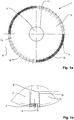
- FIG. 1a shows a plan view of the device 1 with a Monopile 2.
- This consists of interconnected, elastic plates 3 made of rubber, which are one to two inches thick.
- the plates 3 may be bonded together by vulcanization or by suitable positive locking fasteners (not shown).
- the interconnected elastic plates 3 are in the form of a disc having a circular contour and a circular, central opening 11.
- In the central opening 11 is the offshore structure to be protected 2, namely a monopile of a wind turbine, arranged.
- the radius of the device 1 is about three times as long as the radius of the offshore structure 2, with respect to the horizontal plane in which the device 1 is attached to the monopile 2, namely at the level of the seabed. 8
- the disc formed from the rubber plates 3 is attached watertight to the monopile 2, so that no seawater can penetrate under the device 1 through the central opening 11.
- the elastic plate 3 or the elastic plates 3 made of rubber lie on the seabed 8, wherein the elasticity unevenness of the seabed 8 can be compensated.
- weight elements 4 are mounted on the plates 3, which press the plates 3 at the edges down into the seabed and thus seal. As a result, an effective scouring protection is achieved.
- the weight elements 4 are shown for reasons of clarity only on two opposite circle segments, but in fact 13 weight elements 4 are provided along the entire disc edge.
- the weight elements 4 have a substantially rectangular base area.
- the weight elements 4 are aligned on the plates 3 so that the (imaginary) longitudinal axis 12 of each weight element 4 extends in the direction of the offshore structure 2 and thus meet all longitudinal axes 12 in the center of the device 1 and the monopile 2.
- FIG. 1b shows a section FIG. 1 a in a detail view.
- the weight elements 4 are arranged at the edge of a circle segment of the plates 3, wherein the circumference 5 of the circular segment is about one meter.
- the weight elements 4 each have a width of about seventeen centimeters and a distance 6 of about three centimeters.
- the total mass of the weight elements 4 per meter circumference 5 is about fifty to five hundred kilograms, per weight element 4 thus ten to a hundred kilograms.
- FIG. 2 shows partial views a, b, c of another embodiment of the device 1 in vertical section. This has stiffening elements 7 on the underside. It is shown that the rubber sheets 3 should be tightly fastened to the foundation body of the offshore structure 2.
- the FIG. 2b shows a sunken by about two meters seabed.
- FIG 2d a device 1 without stiffening elements 7 is shown. This results in a curved shape 14 of the plates, which is basically hydrodynamically favorable. However, in the case shown, the curvature 14 is too pronounced, so that Kolk promoting turbulence arise.
- Cheaper is a lower curvature 14 ', as in Figure 2c shown in dashed lines. This can be adjusted by selecting the mass of the weight elements 4.
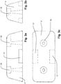
- FIG. 3a shows a weight element 4 in longitudinal section, FIG. 3b in cross-section and Figure 3c in the plan view.
- the weight element 4 has the basic shape of an upwardly tapered cuboid, which has the shape of an isosceles, symmetrical trapezium in longitudinal section and in cross section.
- the weight elements 4 shown have, based on their base area, a length of 3.80 m and a width of 1.70 m.
- the cuboid tapers quantitatively such that there is a deviation from the vertical of about 15 degrees.
- the corners are also rounded. On the one hand, this results in a favorable hydrodynamic shape, because no vortex and unfavorable currents of the seawater are produced at the weight elements 4.
- Another essential advantage of the upwardly tapering shape is that portions of the plates 3 can lower elastically downwards without the weight elements 4 then coming into contact in the region of a curvature.
- the weight elements 4 also have two through openings 15 for the insertion of fastening elements (not shown). As a result, the weights can be permanently attached to the rubber plates 3. Even with a decrease in the rubber plates 3 and the formation of a slope or curvature, as in FIGS. 2c and 2d shown, a secure fixation is guaranteed.
- two lower recesses 17 are provided for a weight element 4 in each case. These serve as an assembly aid and facilitate gripping the weight element 4, when this is to be transported and then attached to the elastic plates 3.
- FIG. 4a shows another embodiment of the weight element 4 in longitudinal section, FIG. 4b in cross-section and Figure 4c in the plan view.
- the weight element 4 has on its underside a concavely inwardly or upwardly curved indentation 9.
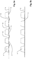
- FIG. 5a shows a vertical section through the device 1 with weight elements 4 with a lower indentation 9.
- the weight elements 4 thus correspond to those in the Figures 4a, 4b and 4c shown embodiment.
- the weight elements 4 shown in cross-section are fixed on the upper side of the elastic plates 3 and permanently fixed.
- indentations 9 a wrinkling 10 between the weight elements 4. Although the folds 10 in the elastic plates 3 between the weight elements 4 down, so are bent in the region of the interstices 16 in the direction of the seabed 8, thereby Wells 10 is formed. This is done by the fact that the Indentations 9 form a concave guide for the rubber sheets 3, whereby the rubber sheets 3 are wave-shaped, as in FIG. 5a shown. As a result, a harmful wrinkling is avoided upwards in the area of the interstices 16 and the device 1 also seals in the edge areas and protects offshore structures 2 from being overcast.
- FIG. 5b shows weight elements 4 without indentation. If a greater sinking of the seabed and thus wrinkling downwards are not to be expected, this embodiment of the weight elements 4 can be used.
- FIG. 6 shows a perspective, horizontally cutaway detail of another embodiment of the device 1 with a flexible stiffener 18.
- This includes a stiffening profile 19 made of flexible plastic.
- the stiffening profile 19 is fastened by means of suitable fastening means on the elastic plates 3.
- a stiffening wall 20 is arranged made of rubber, which may have a fabric insert and is tightly mounted on the plates 3. The attachment can be done by adhesive or vulcanization.
- the upper stiffening wall 20 together with the elastic plates 3 forms a closed cavity 21 which is filled with a medium.
- a medium for example, water or air in question.
Landscapes
- Engineering & Computer Science (AREA)
- General Engineering & Computer Science (AREA)
- Mechanical Engineering (AREA)
- Civil Engineering (AREA)
- Structural Engineering (AREA)
- Environmental & Geological Engineering (AREA)
- Ocean & Marine Engineering (AREA)
- Revetment (AREA)
Claims (9)
- Dispositif (1) de protection contre l'érosion d'ouvrages de mer (2), qui comprend une ou plusieurs plaques élastiques (3) en caoutchouc reliées entre elles et des éléments de poids (4), qui sont fixés au niveau de la zone de bord du dispositif (1) sur la plaque élastique (3) ou les plastiques élastiques (3) à l'aide de moyens de fixation, caractérisé en ce que les éléments de poids (4) se rétrécissent vers le haut et présentent en coupe longitudinale et/ou en coupe transversale la forme d'un trapèze symétrique isocèle.
- Dispositif (1) selon la revendication 1, caractérisé en ce que la plaque élastique (3) ou les plaques élastiques (3) en caoutchouc présentent une épaisseur de un à deux centimètres.
- Dispositif (1) selon la revendication 1 ou la revendication 2, caractérisé en ce que la plaque élastique (3) ou les plastiques élastiques (3) reliées entre elles forment un disque avec un contour circulaire ou approximativement circulaire, au milieu duquel l'ouvrage de mer (2) est agencé.
- Dispositif (1) selon l'une quelconque des revendications précédentes, caractérisé en ce que le rayon du dispositif (1) est à peu près trois fois aussi long que le rayon de l'ouvrage de mer (2) dans le plan, dans lequel le dispositif (1) est agencé.
- Dispositif (1) selon l'une quelconque des revendications précédentes, caractérisé en ce que les éléments de poids (4) présentent une surface de base sensiblement rectangulaire, dont les axes longitudinaux sont dirigés respectivement en direction de l'ouvrage de mer (2).
- Dispositif (1) selon l'une quelconque des revendications précédentes, caractérisé en ce que les éléments de poids (4) sont constitués sensiblement de métal.
- Dispositif (1) selon l'une quelconque des revendications précédentes, caractérisé en ce que les coins des éléments de poids (4) sont arrondis.
- Dispositif (1) selon l'une quelconque des revendications précédentes, caractérisé en ce que les éléments de poids (4) présentent au niveau de la face inférieure un renfoncement (9), qui est incurvé de façon concave en coupe transversale.
- Dispositif (1) selon l'une quelconque des revendications précédentes, caractérisé en ce qu'au moins un renforcement souple (17) est prévu, qui comprend un profil de renforcement (19) et une paroi de renforcement (20) agencée au-dessus du profil de renforcement (19), dans lequel la paroi de renforcement (20) forme une cavité fermée (21), qui est remplie d'un agent.
Applications Claiming Priority (2)
| Application Number | Priority Date | Filing Date | Title |
|---|---|---|---|
| DE102012103537 | 2012-04-22 | ||
| PCT/DE2013/100147 WO2013159770A1 (fr) | 2012-04-22 | 2013-04-22 | Dispositif de protection contre l'érosion d'ouvrages en mer |
Publications (2)
| Publication Number | Publication Date |
|---|---|
| EP2841654A1 EP2841654A1 (fr) | 2015-03-04 |
| EP2841654B1 true EP2841654B1 (fr) | 2016-12-28 |
Family
ID=48626225
Family Applications (1)
| Application Number | Title | Priority Date | Filing Date |
|---|---|---|---|
| EP13728938.5A Not-in-force EP2841654B1 (fr) | 2012-04-22 | 2013-04-22 | Dispositif de protection contre l'érosion d'ouvrages en mer |
Country Status (4)
| Country | Link |
|---|---|
| US (1) | US20150078834A1 (fr) |
| EP (1) | EP2841654B1 (fr) |
| CN (1) | CN104411890A (fr) |
| WO (1) | WO2013159770A1 (fr) |
Families Citing this family (1)
| Publication number | Priority date | Publication date | Assignee | Title |
|---|---|---|---|---|
| DE102015102065A1 (de) | 2015-02-12 | 2016-08-18 | Anton Kanand | Übergangsvorrichtung für Kolkschutzvorrichtungen von Offshore-Bauwerken |
Family Cites Families (7)
| Publication number | Priority date | Publication date | Assignee | Title |
|---|---|---|---|---|
| US1428595A (en) * | 1921-12-12 | 1922-09-12 | Massey Concrete Products Corp | Cribbing |
| US3214921A (en) * | 1961-12-07 | 1965-11-02 | Shell Oil Co | Pipe laying apparatus |
| NL6708016A (fr) * | 1967-06-09 | 1968-12-10 | ||
| US3529427A (en) * | 1968-11-05 | 1970-09-22 | Delta Diving Ltd | Device for preventing or reducing scours at the lower ends of members supporting marine structures |
| JPS6053124B2 (ja) * | 1982-07-02 | 1985-11-22 | 日建工学株式会社 | 水中構造物の基底部安定用シ−ト |
| US20070009327A1 (en) * | 2003-05-27 | 2007-01-11 | Sanguinetti Peter S | Sediment control device and system |
| DE102008020261A1 (de) * | 2008-04-22 | 2009-10-29 | Kanand, Anton, Dipl.-Ing. | Vorrichtung für den Hochwasser- und Küstenschutz |
-
2013
- 2013-04-22 EP EP13728938.5A patent/EP2841654B1/fr not_active Not-in-force
- 2013-04-22 CN CN201380021191.3A patent/CN104411890A/zh active Pending
- 2013-04-22 WO PCT/DE2013/100147 patent/WO2013159770A1/fr not_active Ceased
- 2013-04-22 US US14/389,496 patent/US20150078834A1/en not_active Abandoned
Also Published As
| Publication number | Publication date |
|---|---|
| US20150078834A1 (en) | 2015-03-19 |
| EP2841654A1 (fr) | 2015-03-04 |
| CN104411890A (zh) | 2015-03-11 |
| WO2013159770A1 (fr) | 2013-10-31 |
Similar Documents
| Publication | Publication Date | Title |
|---|---|---|
| EP2386691A1 (fr) | Dispositif et procédé pour une protection contre l'affouillement de constructions offshore | |
| DE102009014920A1 (de) | Fundamentkörper, insbesondere für eine Offshore-Windenergieanlage | |
| DE3321670A1 (de) | Verfahren zum schuetzen ortsfester konstruktionen in wasser gegen eisfelder und schutzeinrichtung | |
| EP2591176B1 (fr) | Installation en mer, en particulier éolienne | |
| DE10056857B4 (de) | Verankerungsstabilisierte Trägerboje | |
| DE69333376T2 (de) | Vorrichtung zur Wellenenergiezerstreuung | |
| DE112021001211T5 (de) | Kolkschutzsystem für eine Pfahlgründung eines Offshore-Windparks und zugehöriges Verfahren | |
| EP2847387A1 (fr) | Dispositif anti-affouillement pour ouvrages en mer | |
| DE102009033708A1 (de) | Vorrichtung zur Reduzierung von Eislasten an einer Pfahlgründung für eine Offshore-Windenergieanlage | |
| EP2841654B1 (fr) | Dispositif de protection contre l'érosion d'ouvrages en mer | |
| DE1909799A1 (de) | Wellenbrecher | |
| DE69308837T2 (de) | Ankergerät für eine schwimmkonstruktion, und schwimmkonstruktion | |
| WO2013178202A1 (fr) | Installation photovoltaïque flottant sur l'eau équipée d'un dispositif de lestage | |
| DE102013018503A1 (de) | Offshore-Bauwerk | |
| DE202005003425U1 (de) | Gründung, insbesondere für eine Offshore-Windenergieanlage | |
| DE2344599C2 (de) | Vorrichtung zum Schutz des Fundaments eines teilweise im Wasser eingetauchten Bauwerks gegen Wellen | |
| DE2713756A1 (de) | Auf den meeresboden abzusetzender behaelter zur lagerung von fluessigkeiten | |
| DE202013101650U1 (de) | Wasserschutz- und/oder -haltevorrichtung | |
| DE102015102065A1 (de) | Übergangsvorrichtung für Kolkschutzvorrichtungen von Offshore-Bauwerken | |
| DE102014202049B3 (de) | Vorrichtung zur Bedeckung eines Untergrundes eines fluiden Mediums | |
| DE2162559A1 (de) | Verfahren und Vorrichtung für die Erzeugung und Befestigung von Ablagerungen von Sedimentmaterial am Boden von Gewässern | |
| AT516339A2 (de) | Wehranlage, insbesondere Kiesschleuse | |
| EP3722541B1 (fr) | Bâtiment résistant aux vagues | |
| DE202009008175U1 (de) | Flexible Verankerung schwimmender Teichbelüfter | |
| DE2222427A1 (de) | Klappenventil |
Legal Events
| Date | Code | Title | Description |
|---|---|---|---|
| PUAI | Public reference made under article 153(3) epc to a published international application that has entered the european phase |
Free format text: ORIGINAL CODE: 0009012 |
|
| 17P | Request for examination filed |
Effective date: 20141117 |
|
| AK | Designated contracting states |
Kind code of ref document: A1 Designated state(s): AL AT BE BG CH CY CZ DE DK EE ES FI FR GB GR HR HU IE IS IT LI LT LU LV MC MK MT NL NO PL PT RO RS SE SI SK SM TR |
|
| AX | Request for extension of the european patent |
Extension state: BA ME |
|
| DAX | Request for extension of the european patent (deleted) | ||
| GRAP | Despatch of communication of intention to grant a patent |
Free format text: ORIGINAL CODE: EPIDOSNIGR1 |
|
| INTG | Intention to grant announced |
Effective date: 20160404 |
|
| GRAS | Grant fee paid |
Free format text: ORIGINAL CODE: EPIDOSNIGR3 |
|
| STAA | Information on the status of an ep patent application or granted ep patent |
Free format text: STATUS: GRANT OF PATENT IS INTENDED |
|
| GRAA | (expected) grant |
Free format text: ORIGINAL CODE: 0009210 |
|
| STAA | Information on the status of an ep patent application or granted ep patent |
Free format text: STATUS: THE PATENT HAS BEEN GRANTED |
|
| AK | Designated contracting states |
Kind code of ref document: B1 Designated state(s): AL AT BE BG CH CY CZ DE DK EE ES FI FR GB GR HR HU IE IS IT LI LT LU LV MC MK MT NL NO PL PT RO RS SE SI SK SM TR |
|
| REG | Reference to a national code |
Ref country code: GB Ref legal event code: FG4D Free format text: NOT ENGLISH |
|
| REG | Reference to a national code |
Ref country code: CH Ref legal event code: EP |
|
| REG | Reference to a national code |
Ref country code: AT Ref legal event code: REF Ref document number: 857412 Country of ref document: AT Kind code of ref document: T Effective date: 20170115 |
|
| REG | Reference to a national code |
Ref country code: IE Ref legal event code: FG4D Free format text: LANGUAGE OF EP DOCUMENT: GERMAN |
|
| REG | Reference to a national code |
Ref country code: DE Ref legal event code: R096 Ref document number: 502013005908 Country of ref document: DE |
|
| PG25 | Lapsed in a contracting state [announced via postgrant information from national office to epo] |
Ref country code: LV Free format text: LAPSE BECAUSE OF FAILURE TO SUBMIT A TRANSLATION OF THE DESCRIPTION OR TO PAY THE FEE WITHIN THE PRESCRIBED TIME-LIMIT Effective date: 20161228 |
|
| REG | Reference to a national code |
Ref country code: FR Ref legal event code: PLFP Year of fee payment: 5 |
|
| REG | Reference to a national code |
Ref country code: LT Ref legal event code: MG4D |
|
| PG25 | Lapsed in a contracting state [announced via postgrant information from national office to epo] |
Ref country code: LT Free format text: LAPSE BECAUSE OF FAILURE TO SUBMIT A TRANSLATION OF THE DESCRIPTION OR TO PAY THE FEE WITHIN THE PRESCRIBED TIME-LIMIT Effective date: 20161228 Ref country code: SE Free format text: LAPSE BECAUSE OF FAILURE TO SUBMIT A TRANSLATION OF THE DESCRIPTION OR TO PAY THE FEE WITHIN THE PRESCRIBED TIME-LIMIT Effective date: 20161228 Ref country code: GR Free format text: LAPSE BECAUSE OF FAILURE TO SUBMIT A TRANSLATION OF THE DESCRIPTION OR TO PAY THE FEE WITHIN THE PRESCRIBED TIME-LIMIT Effective date: 20170329 Ref country code: NO Free format text: LAPSE BECAUSE OF FAILURE TO SUBMIT A TRANSLATION OF THE DESCRIPTION OR TO PAY THE FEE WITHIN THE PRESCRIBED TIME-LIMIT Effective date: 20170328 |
|
| REG | Reference to a national code |
Ref country code: NL Ref legal event code: MP Effective date: 20161228 |
|
| PG25 | Lapsed in a contracting state [announced via postgrant information from national office to epo] |
Ref country code: RS Free format text: LAPSE BECAUSE OF FAILURE TO SUBMIT A TRANSLATION OF THE DESCRIPTION OR TO PAY THE FEE WITHIN THE PRESCRIBED TIME-LIMIT Effective date: 20161228 Ref country code: HR Free format text: LAPSE BECAUSE OF FAILURE TO SUBMIT A TRANSLATION OF THE DESCRIPTION OR TO PAY THE FEE WITHIN THE PRESCRIBED TIME-LIMIT Effective date: 20161228 Ref country code: FI Free format text: LAPSE BECAUSE OF FAILURE TO SUBMIT A TRANSLATION OF THE DESCRIPTION OR TO PAY THE FEE WITHIN THE PRESCRIBED TIME-LIMIT Effective date: 20161228 |
|
| PG25 | Lapsed in a contracting state [announced via postgrant information from national office to epo] |
Ref country code: NL Free format text: LAPSE BECAUSE OF FAILURE TO SUBMIT A TRANSLATION OF THE DESCRIPTION OR TO PAY THE FEE WITHIN THE PRESCRIBED TIME-LIMIT Effective date: 20161228 |
|
| PG25 | Lapsed in a contracting state [announced via postgrant information from national office to epo] |
Ref country code: EE Free format text: LAPSE BECAUSE OF FAILURE TO SUBMIT A TRANSLATION OF THE DESCRIPTION OR TO PAY THE FEE WITHIN THE PRESCRIBED TIME-LIMIT Effective date: 20161228 Ref country code: IS Free format text: LAPSE BECAUSE OF FAILURE TO SUBMIT A TRANSLATION OF THE DESCRIPTION OR TO PAY THE FEE WITHIN THE PRESCRIBED TIME-LIMIT Effective date: 20170428 Ref country code: RO Free format text: LAPSE BECAUSE OF FAILURE TO SUBMIT A TRANSLATION OF THE DESCRIPTION OR TO PAY THE FEE WITHIN THE PRESCRIBED TIME-LIMIT Effective date: 20161228 Ref country code: CZ Free format text: LAPSE BECAUSE OF FAILURE TO SUBMIT A TRANSLATION OF THE DESCRIPTION OR TO PAY THE FEE WITHIN THE PRESCRIBED TIME-LIMIT Effective date: 20161228 Ref country code: SK Free format text: LAPSE BECAUSE OF FAILURE TO SUBMIT A TRANSLATION OF THE DESCRIPTION OR TO PAY THE FEE WITHIN THE PRESCRIBED TIME-LIMIT Effective date: 20161228 |
|
| PGFP | Annual fee paid to national office [announced via postgrant information from national office to epo] |
Ref country code: DE Payment date: 20170425 Year of fee payment: 5 Ref country code: FR Payment date: 20170424 Year of fee payment: 5 Ref country code: GB Payment date: 20170425 Year of fee payment: 5 |
|
| PG25 | Lapsed in a contracting state [announced via postgrant information from national office to epo] |
Ref country code: BG Free format text: LAPSE BECAUSE OF FAILURE TO SUBMIT A TRANSLATION OF THE DESCRIPTION OR TO PAY THE FEE WITHIN THE PRESCRIBED TIME-LIMIT Effective date: 20170328 Ref country code: SM Free format text: LAPSE BECAUSE OF FAILURE TO SUBMIT A TRANSLATION OF THE DESCRIPTION OR TO PAY THE FEE WITHIN THE PRESCRIBED TIME-LIMIT Effective date: 20161228 Ref country code: ES Free format text: LAPSE BECAUSE OF FAILURE TO SUBMIT A TRANSLATION OF THE DESCRIPTION OR TO PAY THE FEE WITHIN THE PRESCRIBED TIME-LIMIT Effective date: 20161228 Ref country code: PT Free format text: LAPSE BECAUSE OF FAILURE TO SUBMIT A TRANSLATION OF THE DESCRIPTION OR TO PAY THE FEE WITHIN THE PRESCRIBED TIME-LIMIT Effective date: 20170428 Ref country code: PL Free format text: LAPSE BECAUSE OF FAILURE TO SUBMIT A TRANSLATION OF THE DESCRIPTION OR TO PAY THE FEE WITHIN THE PRESCRIBED TIME-LIMIT Effective date: 20161228 Ref country code: IT Free format text: LAPSE BECAUSE OF FAILURE TO SUBMIT A TRANSLATION OF THE DESCRIPTION OR TO PAY THE FEE WITHIN THE PRESCRIBED TIME-LIMIT Effective date: 20161228 |
|
| REG | Reference to a national code |
Ref country code: DE Ref legal event code: R097 Ref document number: 502013005908 Country of ref document: DE |
|
| PLBE | No opposition filed within time limit |
Free format text: ORIGINAL CODE: 0009261 |
|
| STAA | Information on the status of an ep patent application or granted ep patent |
Free format text: STATUS: NO OPPOSITION FILED WITHIN TIME LIMIT |
|
| PG25 | Lapsed in a contracting state [announced via postgrant information from national office to epo] |
Ref country code: DK Free format text: LAPSE BECAUSE OF FAILURE TO SUBMIT A TRANSLATION OF THE DESCRIPTION OR TO PAY THE FEE WITHIN THE PRESCRIBED TIME-LIMIT Effective date: 20161228 |
|
| REG | Reference to a national code |
Ref country code: CH Ref legal event code: PL |
|
| 26N | No opposition filed |
Effective date: 20170929 |
|
| REG | Reference to a national code |
Ref country code: IE Ref legal event code: MM4A |
|
| PG25 | Lapsed in a contracting state [announced via postgrant information from national office to epo] |
Ref country code: MC Free format text: LAPSE BECAUSE OF FAILURE TO SUBMIT A TRANSLATION OF THE DESCRIPTION OR TO PAY THE FEE WITHIN THE PRESCRIBED TIME-LIMIT Effective date: 20161228 |
|
| PG25 | Lapsed in a contracting state [announced via postgrant information from national office to epo] |
Ref country code: CH Free format text: LAPSE BECAUSE OF NON-PAYMENT OF DUE FEES Effective date: 20170430 Ref country code: SI Free format text: LAPSE BECAUSE OF FAILURE TO SUBMIT A TRANSLATION OF THE DESCRIPTION OR TO PAY THE FEE WITHIN THE PRESCRIBED TIME-LIMIT Effective date: 20161228 Ref country code: LI Free format text: LAPSE BECAUSE OF NON-PAYMENT OF DUE FEES Effective date: 20170430 Ref country code: LU Free format text: LAPSE BECAUSE OF NON-PAYMENT OF DUE FEES Effective date: 20170422 |
|
| REG | Reference to a national code |
Ref country code: BE Ref legal event code: MM Effective date: 20170430 |
|
| PG25 | Lapsed in a contracting state [announced via postgrant information from national office to epo] |
Ref country code: IE Free format text: LAPSE BECAUSE OF NON-PAYMENT OF DUE FEES Effective date: 20170422 |
|
| PG25 | Lapsed in a contracting state [announced via postgrant information from national office to epo] |
Ref country code: BE Free format text: LAPSE BECAUSE OF NON-PAYMENT OF DUE FEES Effective date: 20170430 |
|
| PG25 | Lapsed in a contracting state [announced via postgrant information from national office to epo] |
Ref country code: MT Free format text: LAPSE BECAUSE OF FAILURE TO SUBMIT A TRANSLATION OF THE DESCRIPTION OR TO PAY THE FEE WITHIN THE PRESCRIBED TIME-LIMIT Effective date: 20161228 |
|
| REG | Reference to a national code |
Ref country code: DE Ref legal event code: R119 Ref document number: 502013005908 Country of ref document: DE |
|
| GBPC | Gb: european patent ceased through non-payment of renewal fee |
Effective date: 20180422 |
|
| PG25 | Lapsed in a contracting state [announced via postgrant information from national office to epo] |
Ref country code: DE Free format text: LAPSE BECAUSE OF NON-PAYMENT OF DUE FEES Effective date: 20181101 |
|
| PG25 | Lapsed in a contracting state [announced via postgrant information from national office to epo] |
Ref country code: GB Free format text: LAPSE BECAUSE OF NON-PAYMENT OF DUE FEES Effective date: 20180422 |
|
| PG25 | Lapsed in a contracting state [announced via postgrant information from national office to epo] |
Ref country code: FR Free format text: LAPSE BECAUSE OF NON-PAYMENT OF DUE FEES Effective date: 20180430 |
|
| REG | Reference to a national code |
Ref country code: AT Ref legal event code: MM01 Ref document number: 857412 Country of ref document: AT Kind code of ref document: T Effective date: 20180422 |
|
| PG25 | Lapsed in a contracting state [announced via postgrant information from national office to epo] |
Ref country code: HU Free format text: LAPSE BECAUSE OF FAILURE TO SUBMIT A TRANSLATION OF THE DESCRIPTION OR TO PAY THE FEE WITHIN THE PRESCRIBED TIME-LIMIT; INVALID AB INITIO Effective date: 20130422 |
|
| PG25 | Lapsed in a contracting state [announced via postgrant information from national office to epo] |
Ref country code: AT Free format text: LAPSE BECAUSE OF NON-PAYMENT OF DUE FEES Effective date: 20180422 Ref country code: CY Free format text: LAPSE BECAUSE OF FAILURE TO SUBMIT A TRANSLATION OF THE DESCRIPTION OR TO PAY THE FEE WITHIN THE PRESCRIBED TIME-LIMIT Effective date: 20161228 |
|
| PG25 | Lapsed in a contracting state [announced via postgrant information from national office to epo] |
Ref country code: MK Free format text: LAPSE BECAUSE OF FAILURE TO SUBMIT A TRANSLATION OF THE DESCRIPTION OR TO PAY THE FEE WITHIN THE PRESCRIBED TIME-LIMIT Effective date: 20161228 |
|
| PG25 | Lapsed in a contracting state [announced via postgrant information from national office to epo] |
Ref country code: TR Free format text: LAPSE BECAUSE OF FAILURE TO SUBMIT A TRANSLATION OF THE DESCRIPTION OR TO PAY THE FEE WITHIN THE PRESCRIBED TIME-LIMIT Effective date: 20161228 |
|
| PG25 | Lapsed in a contracting state [announced via postgrant information from national office to epo] |
Ref country code: AL Free format text: LAPSE BECAUSE OF FAILURE TO SUBMIT A TRANSLATION OF THE DESCRIPTION OR TO PAY THE FEE WITHIN THE PRESCRIBED TIME-LIMIT Effective date: 20161228 |