EP2842013B1 - Systemes et methodes de gestion de l'affichage de contenu sur un dispositif électronique par la détection de zones couvertes de l'affichage - Google Patents
Systemes et methodes de gestion de l'affichage de contenu sur un dispositif électronique par la détection de zones couvertes de l'affichage Download PDFInfo
- Publication number
- EP2842013B1 EP2842013B1 EP13714801.1A EP13714801A EP2842013B1 EP 2842013 B1 EP2842013 B1 EP 2842013B1 EP 13714801 A EP13714801 A EP 13714801A EP 2842013 B1 EP2842013 B1 EP 2842013B1
- Authority
- EP
- European Patent Office
- Prior art keywords
- electronic device
- user
- touchscreen
- graphic
- display
- Prior art date
- Legal status (The legal status is an assumption and is not a legal conclusion. Google has not performed a legal analysis and makes no representation as to the accuracy of the status listed.)
- Active
Links
Images



Classifications
-
- G—PHYSICS
- G06—COMPUTING OR CALCULATING; COUNTING
- G06F—ELECTRIC DIGITAL DATA PROCESSING
- G06F3/00—Input arrangements for transferring data to be processed into a form capable of being handled by the computer; Output arrangements for transferring data from processing unit to output unit, e.g. interface arrangements
- G06F3/01—Input arrangements or combined input and output arrangements for interaction between user and computer
- G06F3/03—Arrangements for converting the position or the displacement of a member into a coded form
- G06F3/041—Digitisers, e.g. for touch screens or touch pads, characterised by the transducing means
- G06F3/0412—Digitisers structurally integrated in a display
-
- G—PHYSICS
- G06—COMPUTING OR CALCULATING; COUNTING
- G06F—ELECTRIC DIGITAL DATA PROCESSING
- G06F1/00—Details not covered by groups G06F3/00 - G06F13/00 and G06F21/00
- G06F1/16—Constructional details or arrangements
- G06F1/1613—Constructional details or arrangements for portable computers
- G06F1/1626—Constructional details or arrangements for portable computers with a single-body enclosure integrating a flat display, e.g. Personal Digital Assistants [PDAs]
-
- G—PHYSICS
- G06—COMPUTING OR CALCULATING; COUNTING
- G06F—ELECTRIC DIGITAL DATA PROCESSING
- G06F1/00—Details not covered by groups G06F3/00 - G06F13/00 and G06F21/00
- G06F1/16—Constructional details or arrangements
- G06F1/1613—Constructional details or arrangements for portable computers
- G06F1/1633—Constructional details or arrangements of portable computers not specific to the type of enclosures covered by groups G06F1/1615 - G06F1/1626
- G06F1/1637—Details related to the display arrangement, including those related to the mounting of the display in the housing
- G06F1/1652—Details related to the display arrangement, including those related to the mounting of the display in the housing the display being flexible, e.g. mimicking a sheet of paper, or rollable
-
- G—PHYSICS
- G06—COMPUTING OR CALCULATING; COUNTING
- G06F—ELECTRIC DIGITAL DATA PROCESSING
- G06F1/00—Details not covered by groups G06F3/00 - G06F13/00 and G06F21/00
- G06F1/16—Constructional details or arrangements
- G06F1/1613—Constructional details or arrangements for portable computers
- G06F1/1633—Constructional details or arrangements of portable computers not specific to the type of enclosures covered by groups G06F1/1615 - G06F1/1626
- G06F1/1684—Constructional details or arrangements related to integrated I/O peripherals not covered by groups G06F1/1635 - G06F1/1675
- G06F1/1694—Constructional details or arrangements related to integrated I/O peripherals not covered by groups G06F1/1635 - G06F1/1675 the I/O peripheral being a single or a set of motion sensors for pointer control or gesture input obtained by sensing movements of the portable computer
-
- G—PHYSICS
- G06—COMPUTING OR CALCULATING; COUNTING
- G06F—ELECTRIC DIGITAL DATA PROCESSING
- G06F3/00—Input arrangements for transferring data to be processed into a form capable of being handled by the computer; Output arrangements for transferring data from processing unit to output unit, e.g. interface arrangements
- G06F3/01—Input arrangements or combined input and output arrangements for interaction between user and computer
- G06F3/017—Gesture based interaction, e.g. based on a set of recognized hand gestures
-
- G—PHYSICS
- G06—COMPUTING OR CALCULATING; COUNTING
- G06F—ELECTRIC DIGITAL DATA PROCESSING
- G06F3/00—Input arrangements for transferring data to be processed into a form capable of being handled by the computer; Output arrangements for transferring data from processing unit to output unit, e.g. interface arrangements
- G06F3/01—Input arrangements or combined input and output arrangements for interaction between user and computer
- G06F3/048—Interaction techniques based on graphical user interfaces [GUI]
- G06F3/0487—Interaction techniques based on graphical user interfaces [GUI] using specific features provided by the input device, e.g. functions controlled by the rotation of a mouse with dual sensing arrangements, or of the nature of the input device, e.g. tap gestures based on pressure sensed by a digitiser
- G06F3/0488—Interaction techniques based on graphical user interfaces [GUI] using specific features provided by the input device, e.g. functions controlled by the rotation of a mouse with dual sensing arrangements, or of the nature of the input device, e.g. tap gestures based on pressure sensed by a digitiser using a touch-screen or digitiser, e.g. input of commands through traced gestures
-
- G—PHYSICS
- G06—COMPUTING OR CALCULATING; COUNTING
- G06F—ELECTRIC DIGITAL DATA PROCESSING
- G06F3/00—Input arrangements for transferring data to be processed into a form capable of being handled by the computer; Output arrangements for transferring data from processing unit to output unit, e.g. interface arrangements
- G06F3/01—Input arrangements or combined input and output arrangements for interaction between user and computer
- G06F3/048—Interaction techniques based on graphical user interfaces [GUI]
- G06F3/0487—Interaction techniques based on graphical user interfaces [GUI] using specific features provided by the input device, e.g. functions controlled by the rotation of a mouse with dual sensing arrangements, or of the nature of the input device, e.g. tap gestures based on pressure sensed by a digitiser
- G06F3/0488—Interaction techniques based on graphical user interfaces [GUI] using specific features provided by the input device, e.g. functions controlled by the rotation of a mouse with dual sensing arrangements, or of the nature of the input device, e.g. tap gestures based on pressure sensed by a digitiser using a touch-screen or digitiser, e.g. input of commands through traced gestures
- G06F3/04883—Interaction techniques based on graphical user interfaces [GUI] using specific features provided by the input device, e.g. functions controlled by the rotation of a mouse with dual sensing arrangements, or of the nature of the input device, e.g. tap gestures based on pressure sensed by a digitiser using a touch-screen or digitiser, e.g. input of commands through traced gestures for inputting data by handwriting, e.g. gesture or text
-
- G—PHYSICS
- G09—EDUCATION; CRYPTOGRAPHY; DISPLAY; ADVERTISING; SEALS
- G09G—ARRANGEMENTS OR CIRCUITS FOR CONTROL OF INDICATING DEVICES USING STATIC MEANS TO PRESENT VARIABLE INFORMATION
- G09G3/00—Control arrangements or circuits, of interest only in connection with visual indicators other than cathode-ray tubes
- G09G3/03—Control arrangements or circuits, of interest only in connection with visual indicators other than cathode-ray tubes specially adapted for displays having non-planar surfaces, e.g. curved displays
- G09G3/035—Control arrangements or circuits, of interest only in connection with visual indicators other than cathode-ray tubes specially adapted for displays having non-planar surfaces, e.g. curved displays for flexible display surfaces
-
- G—PHYSICS
- G06—COMPUTING OR CALCULATING; COUNTING
- G06F—ELECTRIC DIGITAL DATA PROCESSING
- G06F2203/00—Indexing scheme relating to G06F3/00 - G06F3/048
- G06F2203/041—Indexing scheme relating to G06F3/041 - G06F3/045
- G06F2203/04102—Flexible digitiser, i.e. constructional details for allowing the whole digitising part of a device to be flexed or rolled like a sheet of paper
-
- G—PHYSICS
- G09—EDUCATION; CRYPTOGRAPHY; DISPLAY; ADVERTISING; SEALS
- G09G—ARRANGEMENTS OR CIRCUITS FOR CONTROL OF INDICATING DEVICES USING STATIC MEANS TO PRESENT VARIABLE INFORMATION
- G09G2380/00—Specific applications
- G09G2380/02—Flexible displays
-
- G—PHYSICS
- G09—EDUCATION; CRYPTOGRAPHY; DISPLAY; ADVERTISING; SEALS
- G09G—ARRANGEMENTS OR CIRCUITS FOR CONTROL OF INDICATING DEVICES USING STATIC MEANS TO PRESENT VARIABLE INFORMATION
- G09G3/00—Control arrangements or circuits, of interest only in connection with visual indicators other than cathode-ray tubes
- G09G3/001—Control arrangements or circuits, of interest only in connection with visual indicators other than cathode-ray tubes using specific devices not provided for in groups G09G3/02 - G09G3/36, e.g. using an intermediate record carrier such as a film slide; Projection systems; Display of non-alphanumerical information, solely or in combination with alphanumerical information, e.g. digital display on projected diapositive as background
Definitions
- This application generally relates to managing the display of content on a flexible display of an electronic device.
- the application relates to platforms and techniques for rearranging input and notification regions and graphics on a flexible touchscreen of an electronic device in response to a user's interactions with the touchscreen.
- a method for resizing an active area of a flexible display or reconfigurable device including a screen and a controller coupled to the screen is disclosed by US 2008/291225 A1 .
- the controller can initiate a re-sizing program upon detection of an altered shape for the display or device and control the active area of the display based upon the altered shape.
- the controller can further resize fonts or graphic elements or both in correspondence to the dimensions of the active area.
- the controller can initiate the resizing program by altering the flexible display away from a flat position to a non-flat position for example.
- the flexible display can further include a switch that detects the mating of a first end of the flexible display with a second end which initiates the resizing program.
- WO 2012/040363 A1 discloses a system and method for determining the orientation of a mobile device for displaying a graphical user interface and for activating an audio user interface in response to an incoming call or outgoing call.
- the graphical user interface depending on the detected orientation of the mobile device, the graphical user interface can be displayed in a first vertical orientation, a second vertical orientation, a first horizontal orientation, and a second horizontal orientation.
- the audio user interface depending on the detected orientation of the mobile device, a speaker and a microphone can be activated based on the detected vertical orientation so that the activated speaker is near the top of the mobile device and the activated microphone is near the bottom of mobile device.
- Methods and systems for detecting a grip event on a touchscreen display and adjusting the displayed content based on the location of the grip event are disclosed in document US 2012/032979 A1 .
- the content that is covered by a grip event is identified and moved out from under the grip event by adjusting the displayed content layout.
- the area of the grip event may be determined to allow for adjusting the layout of the displayed.
- Alerts may be implemented to alert a user when there is a change in a content that is covered by a grip event.
- the grip event outline may be estimated and menu icons or icons may be positioned and displayed in close contour profile to estimated outline of the grip event.
- a grip event location may be suggested based on a user's touch habits or display content layout.
- An information processing apparatus of the present invention including a touch panel for displaying predetermined information and accepting a touch operation input and a control section for controlling operation of the information processing apparatus itself having the touch panel installed therein is disclosed by EP 2 341 694 A1 .
- the control section includes a processing occurrence detection means for detecting occurrence of a predetermined processing executed by the control section and a panel control means for nullifying a touch operation input against the touch panel when the occurrence of the predetermined processing is detected by the processing occurrence detection means.
- the panel control means cancels nullification of the touch operation input against the touch panel after an elapse of a preset time from the occurrence of the predetermined processing, and sets, in association with the occurred predetermined processing, a touch operation input acceptable range allowing the touch panel to accept the touch operation input with respect to the predetermined processing.
- the electronic device can support communication functionalities, including incoming and outgoing data transmission.
- a user of the electronic device can interact with the touchscreen to facilitate the communication functionalities.
- the electronic device can detect an interaction by the user with the touchscreen.
- the electronic device is a rollable device wherein a flexible touchscreen forms an outer surface of the device when in a rolled configuration, and the interaction by the user can include a user grasping or gripping the rollable device. From the interaction, the electronic device identifies a positioning of the user's hand and determines an appropriate region of the touchscreen to display a graphic for responding to or initiating communication functionality.
- the electronic device displays the graphic within the region and receives input from the user.
- the electronic device can have associated configuration settings that can influence the appropriate region of the touchscreen for displaying the graphics.
- the device displays a graphic associated with a communication function within a display region that is easily accessible to a user.
- the graphic placement prevents the user from inadvertently selecting undesired functionalities.
- the graphic placement allows the user to easily select functions without having to release or change his/her grip on the device.
- the device can determine a size of the user's hand and scale the graphic based on the hand size.
- the user can configure a set of specifications to customize the location of the graphic placement. It should be appreciated that other benefits and efficiencies are envisioned.
- a "rollable device” can be understood to be an electronic device with any combination of hardware and software that can include a touchscreen surface configured to be at least partly rolled or flexed.
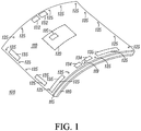
- FIG. 1 depicts an example electronic device 100 consistent with some embodiments. It should be appreciated that the electronic device 100 is merely an example and can include various combinations of hardware and/or software components.
- the electronic device 100 can include a display screen 110.
- the display screen 110 can be flexible, partially flexible, rollable, or partially rollable and can be configured to display graphical information.
- the display screen 110 can be a touchscreen capable of receiving inputs from a user of the electronic device 100.
- the display screen 110 can include touchscreen technologies such as resistive panels, surface acoustic wave (SAW) technology, capacitive sensing (including surface capacitance, projected capacitance, mutual capacitance, and self-capacitance), infrared, optical imaging, dispersive signal technology, acoustic pulse recognition, and/or others.
- SAW surface acoustic wave
- capacitive sensing including surface capacitance, projected capacitance, mutual capacitance, and self-capacitance
- infrared optical imaging
- dispersive signal technology acoustic pulse recognition, and/or others.
- the display screen 110 can use display technology such as electrophoretic displays, electronic paper, polyLED displays, AMOLED displays, OLED displays, liquid crystal displays, electrowetting displays, rotating ball displays, segmented displays, direct drive displays, passive-matrix displays, active-matrix displays, and/or others.
- display technology such as electrophoretic displays, electronic paper, polyLED displays, AMOLED displays, OLED displays, liquid crystal displays, electrowetting displays, rotating ball displays, segmented displays, direct drive displays, passive-matrix displays, active-matrix displays, and/or others.
- the electronic device 100 can also include a processing module 120 that can be an integrated circuit containing a processor and other components configured to process user input and sensor data, and manage content display functionalities as discussed herein. As shown in FIG. 1 , the processing module 120 can be located underneath or adjacent to the flexible battery 180, or can be located in other areas.
- a processing module 120 can be an integrated circuit containing a processor and other components configured to process user input and sensor data, and manage content display functionalities as discussed herein.
- the processing module 120 can be located underneath or adjacent to the flexible battery 180, or can be located in other areas.
- the electronic device 100 is further configured with a set of overlap sensors 125, optional sets of touch sensors 135, and an optional additional sensor 119.
- the set of overlap sensors 125 can be placed on or embedded within the display screen 110 so that, when the electronic device 100 is rolled, the overlap sensors 125 can detect, sense, and/or refine a positioning of an overlap region(s) of the display screen 110.
- the set of overlap sensors 125 can be CMOS image sensors that can be embedded among display pixels of the display screen 110. Additional overlap sensors (not shown) may be placed on or embedded within the flexible battery 180 and can be CMOS image sensors or other sensors.
- the flattened display screen 110 is rectangular in shape; however, any flattened shape is possible including circular, oval, triangular, polygonal, and irregular (e.g., like a flower, an alphanumeric character, or a leaf).
- the set of overlap sensors 125 can be positioned closer or farther from the edges of the respective display screen 110 (or flexible battery 180). Further, it should be appreciated that there can be any number of overlap sensors 125 positioned in any arrangement or orientation on the display screen 110 (or the flexible battery 180). For example, there can be overlap sensors positioned throughout the center area of the display screen 110. In cases where the electronic device 100 is rolled into a more conical or otherwise irregular shape, the overlap sensors positioned near or around the center area, in addition to some of the overlap sensors near the edges, can be blocked or otherwise not detect any light.
- the electronic device 100 can determine the extent of overlap of the display screen 110 with itself by briefly illuminating the entire display screen 110 using a particular light wavelength and sensing which of the overlap sensors 125 receive or do not receive that light. Based on the sensor information, the electronic device 100 can calculate an area where the display screen 110 overlaps with itself. More particularly, the electronic device can detect or approximate the overlap area based which of the overlap sensors 125 do not receive the initial light wavelength or detect any ambient light. A non-overlap area can be defined by the overlap sensors 125 that receive a combination of one or more of the initial light wavelength and ambient light.
- the overlap sensors 125 that do or do not receive the initial light wavelength and ambient light will vary based on the shape or configuration of the device (e.g., rolled to be conical, cylindrical, etc.), whether the display screen 110 is partially blocked by another structure (e.g., a table or support stand), and/or other factors. For example, if the electronic device 100 is rolled into a conical shape, then some overlap sensors 125 on one end of a particular edge of the electronic device 100 will not detect any light while other overlap sensors 125 on the opposite end of the same edge will detect light. In embodiments, the display screen 110 can include a greater concentration of overlap sensors 125 near the ends of the edges to more accurately detect the overlap regions associated with conical or otherwise irregular configurations.
- the optional touch sensors 135 can sense or detect user contact to control some display functionalities of the electronic device 100.
- the touch sensors 135 are dynamically-determined areas of the display screen 110 when the display is configured as a touchscreen.
- the touch sensors 135 are buttons or keys. As shown in FIG. 1 , the touch sensors 135 can be located underneath or adjacent to the flexible battery 180, or can be located in other areas.
- the additional sensor 119 can be any type of imaging sensor or detection component, such as a camera or proximity sensor, that can locate objects and detect changes in positions of objects within a proximity of the electronic device 100.
- the additional sensor 119 can identify a user's position in relation to a section of the rolled-up electronic device 100 and can "follow" the user's movement around the outside of the electronic device 100.
- the additional sensor 119 may detect whether sections of the display screen 110 are obscured, for example if the electronic device 100 is lying on a table.
- the electronic device 100 can support a variety of functionalities and applications.
- the electronic device 100 can support communication functionalities such as telephone calls, text messaging, video calls, Internet browsing, emailing, and/or the like.
- piezo elements 132, 134 are positioned and configured to act as microphones and speakers for supporting telephony and other voice functions.
- a first set of piezo elements 132 can act as microphones and a second set of piezo elements 134 can perform as speakers.
- the piezo elements 132 can act as speakers and the piezo elements 134 can act as microphones, depending on the usage configuration of the device 100.
- the electronic device 100 can support applications such as games, utilities (e.g., calculators, camera applications, etc.), configuration applications, and/or the like.
- the electronic device 100 can also support voice-activation technology that allows users to initiate and operate functions and applications of the electronic device 100.
- the electronic device 100 can be configured to connect to various wired or wireless personal, local, or wide area networks to facilitate communication with network components and/or other devices.
- the various functionalities and applications of the electronic device 100 can have associated display regions and graphics configured for presentation or display on the display screen 110.
- the electronic device 100 can receive inputs, selections, and/or the like via virtual keys displayed on the display screen 110 of the electronic device 100.
- a telephone application of the electronic device 100 can have a graphic including information or selection options such as a dialpad (e.g., a Bell-type dialpad), a caller ID box, various selections associated with functions of the telephone application (e.g., "Dial,” “End,” etc.), and/or others.
- a text messaging application of the electronic device 100 can have a graphic including information or selection options such as a keyboard (e.g., a QWERTY keyboard), a text history, a contact ID, various selections associated with functions of the text messaging application (e.g., "Send,” "Cancel,” etc.), and/or others.
- a keyboard e.g., a QWERTY keyboard
- a text history e.g., a text history
- a contact ID e.g., "Send,” "Cancel,” etc.
- various selections associated with functions of the text messaging application e.g., "Send,” "Cancel,” etc.
- the graphic displayed by the electronic device can include any combination of content that can be displayed such as, for example, characters, letters, icons, images, numbers, and/or the like.
- the processing module 120 of the electronic device 100 can be configured to manage the display of the graphics based on accelerometer 116 measurements, locations of user contact with the display screen 110, viewing positions of the user, and/or other variables. More particularly, the display screen 110 positions the graphics such that, for example, a user's hand will not obscure the displayed graphics. Further, for example, the display screen 110 positions the graphics in regions that allow the user to easily and effectively select options or input information without having to release contact with or re-grip the electronic device 100. In embodiments, a user can specify a set of configuration options that can refine or customize the display of the graphics.
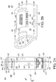
- FIG. 2A and FIG. 2B depict different views of an example electronic device 200 in two configurations 205, 207 in accordance with embodiments.
- the configuration 205 shows a rectangular flexible display (such as the display screen 110) rolled into a tube-like shape and the configuration 207 shows a rectangular flexible display rolled into a "pinch" configuration.
- other configurations are envisioned, including cone-like shapes (see FIG. 4 ) or other oblique or irregular shapes.
- the embodiments envision the configurations 205, 207 as being rolled or shaped either "long-wise” or "short-wise.”
- the configuration 205 as depicted in FIG. 2A is configured such that a display screen 210 is on the outside surface and a flexible battery 280 is on the inside surface.
- the electronic device configuration 207 as depicted in FIG. 2B also has the display screen 210 on the outside surface and the flexible battery 280 doubles over itself in a "pinch" configuration, which has a tear-drop-shaped cross section.
- a processing module 220 can be located on a side of the electronic device opposite from the display screen 210.
- the processing module 220 can include an accelerometer 216 that can determine an orientation of the electronic device in each configuration 205, 207 with respect to gravity. For example, referring to FIGs.
- gravity can pull in the negative z-axis direction such that the device of configuration 205 is standing "on end” and the device of configuration 207 has its "pinch” region pointing "down.”
- the electronic device 200 can also be configured with an additional sensor 219 to help determine a viewing position of a user, track movements of the user, detect nearby objects or surfaces, and/or perform other optical detection functionalities.
- Each of the configurations 205, 207 also depict a graphic 230 that can be displayed on the display screen 210.
- the graphic 230 can indicate an incoming communication with options to open 231 or ignore 233 the communication.
- the device can determine the gravitational direction (e.g., negative z-axis direction) via the accelerometer 216, and can orient or arrange the graphic 230 in an upright position with respect to the gravitational direction.
- the graphic 230 in each of the configurations 205, 207 is oriented in an upright position (z-axis direction).
- the arrangement of the graphic 230 is independent of the orientation or positioning of the electronic device. For example, if the electronic device of the configuration 205 falls on its side, then the device can rotate the graphic 230 orientation such that the graphic 230 is still arranged upright with respect to gravity.
- a set of overlap sensors 225 as illustrated with respect to the configuration 205 can be configured to detect, sense, or otherwise locate an overlap region 204 of the electronic device. More particularly, the set of overlap sensors 225 can sense or detect events indicating that at least part of the display screen 210 is obscured as a result of an overlap with itself, the flexible battery 280, and/or other components. In some cases, the set of overlap sensors 225 can detect an overlap with a non-display element, such as a desktop. The overlap sensors 225 can be positioned on the display screen 210 in any type of configuration, as discussed with respect to FIG. 1 . As shown in FIG. 2A , the overlap region 204 is defined by lines 212 and 214.
- the sensors receiving that wavelength of light and the sensors not receiving that wavelength of light can be analyzed to determine the extent of the overlap region 204.
- the flexible display screen 210 can be illuminated except for the overlap region 204. It should be appreciated that the systems and methods contemplate various orientations, amounts of, and location placements for the optional sensor 219 and the set of overlap sensors 225.
- one or more overlap sensors 225 on one edge of the display screen 210 can be blocked, and thus detect the overlap region 204, while one or more additional overlap sensors 225 on the opposite edge of the display screen 210 can detect ambient light. More particularly, during an initialization step of the electronic device, the additional overlap sensors 225 that are not blocked can detect ambient light as well as the initialization light of the particular wavelength, and the overlap sensors 225 that are blocked can detect little or no light. The size of the calculated overlap region 204 increases as more overlap sensors 225 do not detect any ambient light or the initialization light.
- one or more overlap sensors 225 on one half of the display screen 210 can be blocked by the surface supporting the electronic device 200, while one or more additional overlap sensors 225 on the other half of the display screen 210 can detect ambient light. More particularly, during an initialization step of the electronic device, the overlap sensors 225 may all detect the initialization light of the particular wavelength but only some of the sensors 225 detect ambient light as well as the initialization light. In other situations, the blocked sensors 225 detect neither initialization light nor ambient light while the other sensors detect both initialization light and ambient light. The size of the blocked overlap region 204 increases as more overlap sensors 225 do not detect any ambient light or the initialization light.
- the electronic device in either configuration 205, 207 can further include a substrate that includes an artificial muscle component that can change shape or size when stimulated by an electric charge.
- the artificial muscle can be an electroactive polymer with piezoelectric materials that can deform when subject to a voltage application, and which also might generate a voltage when mechanically deformed.
- the artificial muscle can activate or engage to hold the electronic device in a position.
- the user can roll the electronic device into a tube-like shape, and the artificial muscle can activate to maintain the shape.
- the bending of the artificial muscle by an external force e.g., the user
- the electronic device can further include piezo elements 232, 234, configured to act as microphones and speakers for supporting telephony and other voice functions, and touch sensors 235.
- FIG. 3 depicts a cross-section view of an electronic device 300. It should be appreciated that the cross-section view is merely an example and the electronic device 300 can include various combinations of components and placements thereof.
- the electronic device 300 can include a display screen 310 with a touch-sensitive layer integrated therein. More particularly, the touch-sensitive layer can sense touch events with, for example, a user's hand.
- the electronic device 300 can include a variable lenticular barrier 305 that can control the direction of the display of content.
- the variable lenticular barrier 305 can display content in any or all directions as indicated by arrows 306 as shown in FIG. 3 .
- a user of the electronic device 300 can control the content display direction via one or more touch sensors 335.
- the electronic device 300 can also have one or more overlap sensors 325 and an optional additional sensor 319, as discussed herein.
- the overlap sensors 325 and the additional sensor 319 can be disposed on the variable lenticular barrier 305, a battery layer 387, or in/on other locations of the electronic device 300, such as within the active matrix of the display screen 310.
- the electronic device 300 can further include piezo elements 332, 334 configured to act as microphones and speakers for supporting telephony and other voice functions.
- the electronic device 300 can further include a substrate 315 that can be capable of supporting the display screen 310.
- the substrate 315 can include an artificial muscle 317 component that can change shape when stimulated by an electric charge.
- the artificial muscle 317 can be an electroactive polymer with piezoelectric materials that can deform when subject to a voltage application, and which also generate a voltage when deformed by external forces.
- the artificial muscle 317 can activate or engage to hold the electronic device 300 in a position.
- the user can roll the electronic device 300 into a tube-like shape, and the artificial muscle 317 can activate to maintain the shape.
- the bending of the artificial muscle 317 by an external force can activate an electrical signal, and a polarity of the signal can indicate whether the electronic device 300 is rolled with the display screen 310 as an inside surface or an outside surface.
- the electronic device 300 can be powered by a battery 380 including one or more battery layers 387 and an electrolyte layer 385.
- the battery layers 387 can be lithium-ion batteries or other battery types or variants, and can be made using various types of conductive material.
- the electrolyte layer 385 can have LiPON or other materials or combinations of materials. It should be appreciated that although the battery is depicted as having two battery layers 387 and one electrolyte layer 385, embodiments contemplate various amounts and combinations of layers, as well as materials and compositions thereof.
- the battery layers 387 and the electrolyte later 385 can be laminated or otherwise affixed to the substrate 315 or other components of the electronic device 300.
- the electronic device 300 can have a processing module 320, an accelerometer 316, and the one or more touch sensors 335 disposed on the battery layer 387.
- the processing module 320 can include an integrated circuit, a processor, and other components, and can be configured to interface with the battery layers 387, the artificial muscle 317, the display screen 310, the variable lenticular barrier 305, the overlap sensors 325, the additional sensor 319, and the one or more touch sensors 335 to process and facilitate the operations and functionalities of the electronic device 300 as discussed herein.
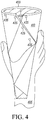
- the rollable device 400 includes a display screen 410 that makes up an outer surface of the rollable device 400 in this configuration, and can display content and receive input from a user at any location(s) of the outer surface. Note that the overlap region in this configuration is triangular rather than rectangular in shape.
- the rollable device 400 can include a set of overlap sensors 425 positioned on the display screen 410 and/or the flexible battery that can detect the overlap area, as discussed herein.
- a user's hand 405 is depicted grasping, gripping, or otherwise making contact with the display screen 410.
- the display screen 410 can be inactive or otherwise not displaying any content when contacted by the user's hand 405. If an illumination mode is initiated subsequent to the contact, the display screen 410 can be configured to obscure any overlap areas as well as any areas or regions associated with the user contact. In other cases, the display screen 410 can be in an illumination mode initiated prior to the user's hand 405 contacting the display screen 410. In yet other situations, the illumination mode can be initiated prior to rolling the display screen 410, and the overlap region is subsequently determined as well as the hand 405 contact region. When contacted, the display screen 410 can be configured to obscure any overlap areas as well as any areas or regions associated with user contact.
- the rollable device 400 can determine a position of the user's hand 405 and components thereof (e.g., thumb, index finger, etc.) after the user's hand 405 makes contact with the display screen 410.
- the display screen 410 can recognize touch events at one or more of a series of nodes of the display screen 410, generate signals corresponding to the touch events, and send the signals to a processor of the rollable device 400.
- the processor can analyze the signals to determine a mapping of the touch events and the corresponding points of contact by the user's hand 405.
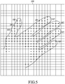
- the display screen interface 500 depicts a two-dimensional view of an outer surface touchscreen of a rollable electronic device (such as the display screen 410 as discussed with respect to FIG. 4 ).
- the display screen interface 500 represents a touchscreen including a series of nodes, depicted as grid line intersections, that can sense a surface contact from, for example, a user's hand. More particularly, the touchscreen can detect a surface contact with one or more contacted nodes 505. Further, the touchscreen can generate a signal(s) in response to the nodes 505 being contacted and transmit the signal(s) to a processor of the electronic device.
- the processor can analyze the signals corresponding to the contacted nodes 505 to determine an outline 510 of a user's hand. More particularly, the processor can approximate the sizes and locations of individual fingers, locate fingertips 507, and can generate the outline 510 according to the approximations. In some cases, the outline 510 can encompass most or all of the contacted nodes 505 at a point in time. In other cases, some user grips will only include the area contacted by the fingertips 507. In embodiments, the processor can determine or approximate a size of the user's hand based on the shape and size of the outline 510 or the size of the fingertips 507 and distance between the detected fingertips 507. Further, the processor can examine the outline 510 to determine which hand (left or right) is contacting the touchscreen, as well as the specific fingers (e.g., thumb, index finger, etc.) and the locations of the specific fingers.
- the processor can examine the outline 510 to determine which hand (left or right) is contacting the touchscreen, as well as the specific fingers (e.g., thumb, index finger
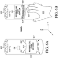
- FIG. 6A and FIG. 6B depict an example rollable electronic device 600 that supports communication functionalities.
- the communication is an incoming call, however other communications and functionalities thereof are envisioned.
- the electronic device 600 can detect the incoming call without, or prior to, any interaction with a user.
- an accelerometer 616 of the electronic device 600 can identify an orientation of the electronic device 600. More particularly, the accelerometer 616 can identify an upward orientation for graphics displayed by the electronic device 600 based on a "z-axis" with respect to gravity. Further, the electronic device 600 can identify a viewing position of the user via an additional sensor 619 such as a camera or proximity sensor.
- the user can be positioned at various locations around the circumference of the electronic device 600.
- the sensor 619 can detect which areas of the touchscreen are exposed or obscured.
- the electronic device 600 can be lying on its side with part of the electronic device 600 contacting a surface and thus obscuring the current "bottom" of the device 600.
- the touchscreen of the electronic device 600 can display a notification 630 of the incoming call.
- the notification 630 can indicate the incoming call and the source of the incoming call.
- the location of the notification 630 can be based on the viewing position of the user and/or the area(s) of the touchscreen that is exposed, as detected via the sensor 619 and overlap sensors (not shown).
- the orientation of the notification 630 can be based on the orientation of the electronic device 600 with respect to gravity as detected by the accelerometer.
- the notification 630 can face "up" even though the electronic device 600 may be on its side.
- the notification 630 can include selectable options to answer 631 or decline 633 the call.
- the touchscreen can display the notification 630 in motion 602 throughout the touchscreen area.
- the motion 602 can be a random or programmed motion that "moves" the notification 630 at various speeds throughout the touchscreen area.
- the motion 602 can correspond to the notification 630 resizing larger or smaller, pulsing, and/or displaying in other movements.
- the notification 630 can display on any area of the touchscreen except for an area defined by an overlap of the touchscreen and/or other non-display elements, such as a desktop, as sensed by one or more overlap sensors.
- the electronic device 600 can be equipped with one or more audio components, such as a piezo element microphone and/or speaker, that can activate or deactivate based on the viewing position of the user, any overlaps in the touchscreen, and/or any obscured or exposed areas or regions. More particularly, the electronic device 600 can identify one of more of the audio components that face toward the user. In this way, the electronic device 600 can efficiently and effectively transmit audio to and/or receive audio from the user.
- the audio components can be speakers or microphones, such as piezoelectric speakers or microphones.
- the touchscreen of the electronic device 600 can sense contact by a user's hand 605.
- the rollable device 600 can identify or determine the components of the user's hand 605 such as, for example, an outline of the user's hand 605, the sizes, types, and locations of the fingertips, and/or other information, as discussed herein.
- the rollable device can examine any configuration settings associated with the display of notifications.
- the configuration settings can specify that the notification graphic 635 should be displayed near or under an index finger 607 of the user.
- the electronic device 600 can terminate the in-motion display of the notification 630 and display a notification graphic 635 (in this case, a notification having a graphic similar to notification 630) at an appropriate region of the touchscreen based on the position of the user's hand 605 and optionally the configuration settings.
- a notification graphic 635 in this case, a notification having a graphic similar to notification 630
- the notification graphic 635 is located near the index finger 607 of the user's right hand 605.
- the user can select to answer 631 or decline 633 the incoming call with his/her index finger 607 without having to release his/her grip of the rollable device 600.
- the user can reposition the notification graphic 635 to any location or region on the touchscreen via various gestures or combinations of gestures. For example, the user can drag-and-drop the graphic 635, swipe at the graphic 635, and/or perform other single- or multi-touch gestures.
- FIG. 7 depicts an example rollable electronic device 700 that supports communication functionalities.
- the electronic device 700 is in a "pinch" configuration (see FIG. 2B ) with the flexible display screen 710 as an outer surface and the flexible battery 780 as an inner surface.
- the communication is an outgoing call, however other communications and functionalities thereof are envisioned.
- a user can use the rollable device 700 to send an outgoing text message.
- the user can initiate the outgoing communication functionalities in various ways. For example, in some cases, the user can select an appropriate function from the electronic device 700 itself, such as from a menu or application. In other cases, the electronic device 700 can initiate the functionalities in response to a voice command received from the user. In further cases, the user can initiate the functionalities via single- or multi-touch gestures with the touchscreen of the electronic device 700, and/or via other interactions with the electronic device 700.
- an accelerometer 716 of the electronic device 700 can identify an orientation of the electronic device 700. More particularly, the accelerometer can identify an upward orientation based on a "z-axis" with respect to gravity. Further, the electronic device 700 can identify a viewing position of the user via a sensor 719 such as a camera or proximity sensor, as discussed herein. For example, the user can be positioned at various locations around the circumference of the electronic device 700. In some embodiments, the sensor 719 can detect which areas of the touchscreen are exposed or obscured. For example, the electronic device 700 can be lying on its side with part of the electronic device 700 contacting a surface.
- the touchscreen of the electronic device 700 can display a dial pad 730 for receiving input from the user.
- the touchscreen can display the dial pad 730 in motion throughout the surface of the touchscreen, as similarly discussed herein with respect to FIG. 6A .
- the location or region of the dial pad 730 can be based on the viewing position of the user and/or the area(s) of the touchscreen that is exposed as detected via the sensor 719 and/or overlap sensors (not shown).
- the orientation of the dial pad 730 can be based on the orientation of the electronic device 700 as detected by the accelerometer 716. For example, the dial pad 730 can face "up" with respect to the z-axis even though the electronic device 700 may be on its side.
- the dial pad 730 can be a Bell-type keypad that includes selectable alphanumeric characters, or other types of keypads or input regions.
- the touchscreen can display a QWERTY keyboard.
- the dial pad 730 can display on any area of the touchscreen except for an area defined by an overlap of the touchscreen, as sensed by one or more overlap sensors (not shown).
- the electronic device 700 can be equipped with one or more audio components, such as piezo elements 732, 734 for use as a microphone and/or a speaker, that can activate or deactivate based on the viewing position of the user, any overlaps in the touchscreen, and/or any obscured or exposed areas or regions. More particularly, the electronic device 700 can identify one of more of the audio components that face toward the user. In this way, the electronic device 700 can efficiently and effectively transmit audio to and/or receive audio from the user.
- the audio components can be speakers or microphones, such as piezoelectric speakers or microphones.
- the touchscreen of the electronic device 700 can sense contact by a user's hand 705.
- the electronic device 700 can identify or determine the components of the user's hand 705 such as, for example, the outline of the user's hand 705, the sizes, types, and locations of the fingertips, and/or other information such as the distance between fingers, as discussed herein.
- the electronic device 700 can examine any configuration settings associated with the display of input regions. For example, the configuration settings can specify that the dial pad 730 should be displayed near the thumb 707 of the user. For further example, the configuration settings can specify that the "5" key of the dial pad 730 should be displayed under the thumb 707 of the user.
- the electronic device 700 can terminate any in-motion display of the dial pad 730 and transition the dial pad 730 to an appropriate location of the touchscreen based on the position of the user's hand 705 and the configuration settings.
- the dial pad 730 is located near the thumb 707 of the user's left hand 705.
- the user can select to call 737 an appropriate party based on the number that is entered into the dial pad 730 via, for example, the thumb 707 or a finger of the other hand.
- the user can reposition the dial pad 730 to any location or region on the touchscreen via various gestures or combinations of gestures. For example, the user can drag-and-drop the dial pad 730, swipe at the dial pad 730, and/or perform other single- or multi-touch gestures.
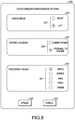
- FIG. 8 details an example user interface of an electronic device (such as the device 100 as shown in FIG. 1 ). More particularly, the user interface can be a configuration options screen 800 that can be displayed on a touchscreen of the electronic device.
- the options screen 800 can allow the user to select various options associated with displaying the notifications and the graphics as discussed herein. It should be appreciated that the options screen 800 and options thereof are examples and can include other various options and combinations of options.
- the options screen 800 includes a handedness selection 805. More particularly, the handedness selection 805 has options 807 for right and left handedness. If the user selects the right handedness option, then the user can envision handling the electronic device primarily with his or her right hand. Similarly, if the user selects the left handedness option, then the user can envision handling the electronic device primarily with his or her left hand. It should be appreciated that in some embodiments, the device can automatically detect which hand (left or right) is handling the electronic device, based on the detected position of fingertips and models of common hand positions, and can modify a handedness setting accordingly.
- the options screen 800 further includes a keypad location section 810 with options 809 related to where a graphic will be displayed on the electronic device.
- the options 809 can include options to display the keypad under a finger or proximal to the finger. For example, if a user desires to initiate a telephone call, then in response to the user grasping or gripping the electronic device, the keypad to enter in an associated telephone number can display under one of the user's fingers or proximal to the user's finger.
- the options screen 800 includes a preferred finger section 815 including options 817 for the user to select a finger from which the graphic location is determined.
- options 817 for the user to select a finger from which the graphic location is determined.
- the graphic to respond to or initiate a communication or function can be displayed under or near the index finger.
- the user can make similar selections for the thumb, middle, ring, and pinky fingers, as shown in FIG. 8 .
- the user can select an update option 820, shown as a virtual key displayed on the touch screen, to save the selected options.
- the user can select a cancel option 825 to cancel any selections made on the options screen 800.
- FIG. 9 illustrates an example electronic device 900 in which the embodiments may be implemented.
- the electronic device 900 can include a processor 920, memory 904 (e.g., hard drives, flash memory, MicroSD cards, and others), a power module 980 (e.g., flexible batteries, wired or wireless charging circuits, etc.), a peripheral interface 908, and one or more external ports 990 (e.g., Universal Serial Bus (USB), HDMI, Firewire, and/or others).
- the electronic device 900 can further include a communication module 912 configured to interface with the one or more external ports 990.
- the communication module 912 can include one or more transceivers functioning in accordance with IEEE standards, 3GPP standards, or other standards, and configured to receive and transmit data via the one or more external ports 990. More particularly, the communication module 912 can include one or more WWAN transceivers configured to communicate with a wide area network including one or more cell sites or base stations to communicatively connect the electronic device 900 to additional devices or components. Further, the communication module 912 can include one or more WLAN and/or WPAN transceivers configured to connect the electronic device 900 to local area networks and/or personal area networks, such as a Bluetooth® network.
- the electronic device 900 can further include one or more sensors 970 such as, for example, accelerometers, gyroscopic sensors (e.g., three angular-axis sensors), proximity sensors (e.g., light detecting sensors, or infrared receivers or transceivers), tilt sensors, cameras, and/or other sensors; and an audio module 931 including hardware components such as a speaker 934 for outputting audio and a microphone 932 for receiving audio.
- the speaker 934 and the microphone 932 can be piezoelectric components.
- the electronic device 900 further includes an input/output (I/O) controller 922, a display screen 910, and additional I/O components 918 (e.g., an artificial muscle 917, capacitors, keys, buttons, lights, LEDs, cursor control devices, haptic devices, and others).
- I/O input/output
- the display screen 910 and the additional I/O components 918 may be considered to form portions of a user interface (e.g., portions of the electronic device 900 associated with presenting information to the user and/or receiving inputs from the user).
- the display screen 910 is a touchscreen display with singular or combinations of display technologies such as electrophoretic displays, electronic paper, polyLED displays, OLED displays, AMOLED displays, liquid crystal displays, electrowetting displays, rotating ball displays, segmented displays, direct drive displays, passive-matrix displays, active-matrix displays, and/or others.
- the display screen 910 can include a thin, transparent touch sensor component superimposed upon a display section that is viewable by a user.
- such displays include capacitive displays, resistive displays, surface acoustic wave (SAW) displays, optical imaging displays, and the like.
- the display screen can also include a lenticular barrier 905 (see FIG. 3 ) configured to control an illumination direction.
- the display screen 910 can be configured to interact with various manipulators, such as a human finger or hand. Each type of manipulator, when brought into contact with the display screen 910, can cause the display screen 910 to produce a signal that can be received and interpreted as a touch event by the processor 920.
- the display screen 910 can also detect any overlap regions associated with the electronic device 900.
- the processor 920 is configured to determine the location of the contact on the surface of the display screen 910, as well as other selected attributes of the touch event (e.g., movement of the manipulator(s) across the surface of the screen, directions and velocities of such movement, touch pressure, touch duration, and others).
- the display screen 910 or one of the additional I/O components 918 can also provide haptic feedback to the user (e.g., a clicking response or keypress feel) in response to a touch event.
- the display screen 910 can have any suitable rectilinear or curvilinear shape, and may be oriented, rolled, or otherwise manipulated in any desired fashion.
- the illustrated embodiments without loss of generality, depict rectangular regions rolled into a tube-like shape (see FIGs. 6A and 6B ).
- embodiments comprehend any range of shapes, sizes, and orientations for the display screen 910 such as, for example, tear drop-like (see FIG. 7 ) or cone-like shapes (see FIG. 4 ), semi-rolled shapes, and/or the like.
- a computer program product in accordance with an embodiment includes a computer usable storage medium (e.g., standard random access memory (RAM), an optical disc, a universal serial bus (USB) drive, or the like) having computer-readable program code embodied therein, wherein the computer-readable program code is adapted to be executed by the processor 920 (e.g., working in connection with an operating system) to implement a user interface method as described below.
- the program code may be implemented in any desired language, and may be implemented as machine code, assembly code, byte code, interpretable source code or the like (e.g., via C, C++, Java, Actionscript, Objective-C, Javascript, CSS, XML, and/or others).
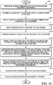
- FIG. 10 is a flowchart of a method 1000 for an electronic device (such as the electronic device 100 as shown in FIG. 1 ) to manage the display of content on a display screen of the electronic device. More particularly, the method 1000 relates to the electronic device managing the display of content in response to receiving an incoming communication.
- an electronic device such as the electronic device 100 as shown in FIG. 1
- the method 1000 relates to the electronic device managing the display of content in response to receiving an incoming communication.
- the method 1000 begins with the electronic device receiving 1005 an incoming communication.
- the incoming communication can be a text message (e.g., SMS, MMS, etc.), telephone call, or other data communication.
- the electronic device optionally determines 1010, via a sensor of the electronic device, a viewing position of the user.
- the sensor can be a camera configured to detect the presence and/or location of a user relative to the display.
- the electronic optionally displays 1015, in motion throughout the touchscreen, a notification of the incoming communication. More particularly, the notification can "bounce" around the touchscreen area of the electronic device so that a user of the electronic device has a greater chance of seeing or noticing the notification.
- the notification can be a pop-up notification that can indicate the communication and/or a source of the communication, and a display region of the notification can be based on the viewing position of the user.
- the electronic device detects 1020 an interaction by the user with the touchscreen.
- the user can grasp the electronic device (such as illustrated in FIG. 4 ) with his/her left or right hand such that multiple fingers of the user's hand are in contact with the touchscreen.
- the electronic device optionally terminates 1025 displaying the notification in motion throughout the touchscreen and identifies 1030, from the interaction, a position of a hand of the user.
- the electronic device can optionally identify finger or fingertip positions of the individual fingers of the hand, the handedness (right or left), and a size of the hand, in accordance with the functionalities as discussed herein.
- the electronic device determines 1035, based on the position of the hand (and optionally the finger position(s) of the finger(s)), a display region on the touchscreen to display a graphic corresponding to the incoming communication.
- the display region can be in proximity to the user's hand, or specifically the user's index finger (or other fingers) such that the user does not need to release or re-grip the electronic device to interact with the graphics.
- the display region can be underneath one of the user's fingers, such as the user's index finger.
- the display region can also be determined based on the viewing position of the user and/or a set of configuration settings relating to preferences of the user.
- the electronic device displays 1040 the graphic within the display region on the touchscreen.
- the electronic device can optionally scale the graphic based on the size of the hand, and the graphic can optionally include a selectable option to respond to the incoming communication. For example, if the incoming communication is a telephone call, then the graphic can include an "answer" option and/or other elements. For further example, if the incoming communication is a text message, then the graphic can include a virtual keyboard or keypad, a "send" option, and/or other elements.
- the electronic device optionally receives 1045 an input from the user within the display region. For example, the user can select to answer a telephone call by contacting a virtual button on a touchscreen or the user can view a text message by touching a key on a virtual keyboard.
- the electronic device optionally executes 1050 an associated function according to the input. For example, the electronic device can connect to an incoming telephone call if the user selects to answer the telephone call, or the electronic device can display and reply to an incoming text message as the user directs. It should be appreciated that other associated functions related to incoming communications are envisioned.
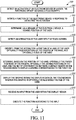
- FIG. 11 is a flowchart of a method 1100 for an electronic device (such as the electronic device 100 as shown in FIG. 1 ) to manage the display of content on a touchscreen of the electronic device. More particularly, the method 1100 relates to the electronic device managing the display of content in response to the user initiating a function such as an outgoing communication or other application.
- a function such as an outgoing communication or other application.
- the method 1100 begins with the electronic device detecting 1105 an activation of the electronic device by a user, wherein the electronic device includes a touchscreen.
- the electronic device initiates 1110 a function of the electronic device in response to detecting the activation.
- the function can be an outgoing communication such as a telephone call or a text message (e.g., SMS, MMS, etc.).
- the function can be associated with an application of the electronic device, such as a calendar function, a calculator function, a game, a camera application, or the like.
- initiating the function results in displaying a graphic on the touchscreen such as, for example, a dialpad.
- the electronic device optionally determines 1115, via a sensor of the electronic device, a viewing position of the user.
- the sensor can be a camera configured to detect the presence and/or location of a user relative to the display.
- the electronic device detects 1120 an interaction by the user with the touchscreen.
- the user can grasp the electronic device (such as illustrated in FIG. 4 ) with his/her left or right hand such that multiple fingers of the user's hand are in contact with the touchscreen.
- the electronic device identifies 1125, from the interaction, a position of a hand of the user.
- the electronic device can optionally identify finger or fingertip positions of the individual fingers of the hand, the handedness (right or left), and a size of the hand, in accordance with the functionalities as discussed herein. It should be appreciated that the electronic device can detect the interaction by the user before initiating the function.
- the electronic device determines 1130, based on the position of the hand (and optionally the finger position(s) of the finger(s)), a display region on the touchscreen to display a graphic corresponding to the associated function.
- the display region can be in proximity to the user's hand, or specifically the user's index finger (or other fingers) such that the user does not need to release or re-grip the electronic device.
- the display region can be underneath one of the user's fingers, such as the user's index finger.
- the display region can also be determined based on the viewing position of the user and/or a set of configuration settings relating to preferences of the user.
- the electronic device displays 1135 the graphic within the display region on the touchscreen.
- the electronic device can optionally scale the graphic based on the calculated size of the hand.
- the graphic can include a selectable option for the user to facilitate a communication and/or perform other functions.
- the graphic can include a dial pad and/or similar elements.
- the graphic can include a virtual keyboard or keypad, a "send" option, and/or other elements.
- the electronic device optionally receives 1140 an input from the user within the display region. For example, the user can enter a telephone number into a dial pad, or enter values into a calculator application.
- the electronic device optionally executes 1145 the function according to the input. For example, the electronic device can dial out to an entered phone number, or the electronic device can perform a calculation based on entered values. It should be appreciated that other associated functions related to outgoing communications and/or other functions are envisioned.
- a method and apparatus effectively and efficiently manages the display of content on a display screen of an electronic device.
- the method and apparatus advantageously allows a user of the electronic device to navigate though functions of the electronic device and input content into graphics without having to adjust a grip or hold on the electronic device. Further, the method and apparatus advantageously re-displays content in response to a user adjusting contact with the touchscreen.
Landscapes
- Engineering & Computer Science (AREA)
- Theoretical Computer Science (AREA)
- General Engineering & Computer Science (AREA)
- Physics & Mathematics (AREA)
- General Physics & Mathematics (AREA)
- Human Computer Interaction (AREA)
- Computer Hardware Design (AREA)
- Telephone Function (AREA)
- User Interface Of Digital Computer (AREA)
Claims (14)
- Procédé pour le contrôle d'un dispositif électronique comprenant un écran tactile flexible, le procédé comprenant :(1005) la réception, au niveau du dispositif électronique, d'une indication d'une communication entrante ;(1015) l'affichage d'une notification de la communication entrante le long d'une surface extérieure d'un écran tactile du dispositif électronique, dans lequel l'écran tactile peut être roulé de manière à former la surface extérieure ;le déplacement de la notification sur la surface extérieure de l'écran tactile ;(1020) la détection d'une interaction par un utilisateur avec l'écran tactile ;(1025) en réponse à la détection de l'interaction par l'utilisateur, terminer l'affichage de la notification le long de la surface extérieure ;(1030) l'identification d'une zone de l'écran tactile définie par l'interaction ;(1035) la détermination, par un processeur se basant sur la zone définie par l'interaction, d'une région d'affichage sur la surface extérieure de l'écran tactile afin d'afficher un graphique pour répondre à une fonctionnalité de communication ou débuter celle-ci ; et (1040) l'affichage, dans la région d'affichage sur l'écran tactile, du graphiquedans lequel la détermination de la région d'affichage sur la surface extérieure de l'écran tactile comprend :l'éclairage de l'affichage avec une lumière d'une longueur d'onde particulière ;l'obtention d'informations de capteurs provenant au moins d'un capteur de recouvrement du dispositif électronique, les informations de capteurs indiquant quel capteur parmi l'au moins un capteur de recouvrement détecte la lumière d'une longueur d'onde particulière ;la détermination, sur base des informations du capteur, d'une zone de recouvrement de la surface extérieure où la surface extérieure se chevauche à l'intérieur de celle-ci ; etla détermination de la région d'affichage dans une zone de la surface extérieure mis à part la zone de recouvrement.
- Procédé selon la revendication 1, dans lequel l'interaction par l'utilisateur avec l'écran tactile est une interaction tactile.
- Procédé selon la revendication 1, dans lequel la zone de l'écran tactile définie par l'interaction correspond à une position de la main d'un utilisateur.
- Procédé selon la revendication 3, comprenant en outre :
(1010) la détermination, via un capteur du dispositif électronique, d'une position de visualisation de l'utilisateur, dans lequel la région d'affichage est en outre déterminée en se basant sur la position de visualisation. - Procédé selon la revendication 4, comprenant en outre :l'identification, sur base de la position de visualisation de l'utilisateur, de quel composant à activer parmi un ou plusieurs composants audio du dispositif électronique ; etl'activation de l'un ou plusieurs composants audio qui ont été identifiés.
- Procédé selon la revendication 3, dans lequel l'affichage du graphique (1040) comprend :l'identification, à partir de l'interaction, de la taille de la main ;la détermination d'une taille du graphique d'entrée sur base de la taille de la main ; etla mise à échelle du graphique sur base de la taille du graphique d'entrée.
- Procédé selon la revendication 3, dans lequel lorsque le graphique est associé à une communication entrante, l'affichage du graphique (1040) comprend :
l'affichage, dans la région d'affichage, d'un panneau interactif pour l'utilisateur afin de répondre à la communication entrante. - Procédé selon la revendication 3, dans lequel la détermination de la région d'affichage sur la surface extérieure de l'écran tactile comprend :(1030) l'identification, à partir de l'interaction, d'une position du doigt d'un doigt de la main ; etla détermination, sur base de la position du doigt, de la région d'affichage.
- Procédé selon la revendication 8, dans lequel le graphique comprend un clavier et dans lequel l'affichage du graphique (1040) comprend :
l'affichage du clavier dans la région d'affichage, dans lequel une touche « 5 » du clavier est affichée au niveau de la position du doigt. - Procédé selon la revendication 3, comprenant en outre :l'identification, à partir de l'interaction, de la main que ce soit la main gauche ou la main droite de l'utilisateur ; etla modification d'un paramètre en fonction de l'identification de la main gauche ou de l'identification de la main droite.
- Procédé selon la revendication 3, dans lequel l'affichage du graphique comprend :la réception, à partir d'un accéléromètre, d'une lecture indiquant une direction gravitationnellement ascendante ;l'identification d'une orientation du graphique sur base de la lecture ; etl'affichage, dans la région d'affichage sur l'écran tactile, du graphique selon l'orientation.
- Dispositif électronique (300), comprenant :un affichage flexible (310) incluant une couche sensible au toucher (335) ;au moins un capteur de recouvrement (325) pour détecter que les sections de l'affichage flexible (310) se chevauchent ; etun processeur (320) configuré pour réaliser une interface avec l'affichage flexible (310) et l'au moins un capteur de recouvrement (325) et pour réaliser les opérations d'une des revendications 3 à 6.
- Dispositif électronique (300) selon la revendication 12, dans lequel le dispositif électronique comprend en outre :un accéléromètre (316), etdans lequel le processeur (320) est en outre configuré pour réaliser une interface avec l'accéléromètre (316) etréaliser un affichage comprenant :la réception, à partir de l'accéléromètre (316), d'une lecture indiquant une direction ascendante du dispositif électronique (300),l'identification d'une orientation du graphique sur base de la lecture et l'affichage, dans la région d'affichage, d'un graphique selon l'orientation.
- Dispositif électronique (300) selon la revendication 12, dans lequel le processeur (320) est en outre configuré pour réaliser des opérations comprenant :
la détection, de l'utilisateur via la couche sensible au toucher (335), d'un geste et le repositionnement du graphique dans la région d'affichage selon le geste.
Applications Claiming Priority (2)
| Application Number | Priority Date | Filing Date | Title |
|---|---|---|---|
| US13/455,930 US9116567B2 (en) | 2012-04-25 | 2012-04-25 | Systems and methods for managing the display of content on an electronic device |
| PCT/US2013/032886 WO2013162783A1 (fr) | 2012-04-25 | 2013-03-19 | Systèmes et procédés pour gérer l'affichage de contenu sur un dispositif électronique par détection de zones masquées de l'affichage |
Publications (2)
| Publication Number | Publication Date |
|---|---|
| EP2842013A1 EP2842013A1 (fr) | 2015-03-04 |
| EP2842013B1 true EP2842013B1 (fr) | 2018-10-10 |
Family
ID=48050307
Family Applications (1)
| Application Number | Title | Priority Date | Filing Date |
|---|---|---|---|
| EP13714801.1A Active EP2842013B1 (fr) | 2012-04-25 | 2013-03-19 | Systemes et methodes de gestion de l'affichage de contenu sur un dispositif électronique par la détection de zones couvertes de l'affichage |
Country Status (4)
| Country | Link |
|---|---|
| US (1) | US9116567B2 (fr) |
| EP (1) | EP2842013B1 (fr) |
| CN (1) | CN104395851B (fr) |
| WO (1) | WO2013162783A1 (fr) |
Families Citing this family (68)
| Publication number | Priority date | Publication date | Assignee | Title |
|---|---|---|---|---|
| US8545340B2 (en) * | 2009-09-10 | 2013-10-01 | Cobra Golf Incorporated | Golf club with directional based graphic |
| US9229625B2 (en) * | 2012-02-06 | 2016-01-05 | Mosaiqq, Inc | System and method for providing a circular computer desktop environment |
| US9075566B2 (en) | 2012-03-02 | 2015-07-07 | Microsoft Technoogy Licensing, LLC | Flexible hinge spine |
| US8935774B2 (en) | 2012-03-02 | 2015-01-13 | Microsoft Corporation | Accessory device authentication |
| US9870066B2 (en) | 2012-03-02 | 2018-01-16 | Microsoft Technology Licensing, Llc | Method of manufacturing an input device |
| US9158383B2 (en) | 2012-03-02 | 2015-10-13 | Microsoft Technology Licensing, Llc | Force concentrator |
| KR101864620B1 (ko) * | 2012-05-09 | 2018-06-07 | 엘지전자 주식회사 | 이동 단말기 및 그것의 제어방법 |
| US20130300590A1 (en) | 2012-05-14 | 2013-11-14 | Paul Henry Dietz | Audio Feedback |
| KR101903742B1 (ko) * | 2012-05-22 | 2018-10-04 | 삼성디스플레이 주식회사 | 표시 장치 |
| US10031556B2 (en) | 2012-06-08 | 2018-07-24 | Microsoft Technology Licensing, Llc | User experience adaptation |
| KR102079348B1 (ko) | 2012-07-30 | 2020-04-07 | 삼성전자주식회사 | 플렉서블 장치 및 그 동작 제어 방법 |
| KR102070244B1 (ko) | 2012-08-01 | 2020-01-28 | 삼성전자주식회사 | 플렉서블 디스플레이 장치 및 그 제어 방법 |
| TW201407249A (zh) * | 2012-08-10 | 2014-02-16 | Yan-Hong Du | 主動式電子紙觸控裝置 |
| KR101892959B1 (ko) * | 2012-08-22 | 2018-08-29 | 삼성전자주식회사 | 플렉서블 디스플레이 장치 및 플렉서블 디스플레이 장치의 제어 방법 |
| KR101869959B1 (ko) * | 2012-08-23 | 2018-07-23 | 삼성전자주식회사 | 플렉서블 및 그 제어 방법 |
| KR102086715B1 (ko) | 2012-11-01 | 2020-03-09 | 삼성전자주식회사 | 가요성 표시부의 화면 출력 제어 방법 및 이를 지원하는 단말기 |
| KR102083981B1 (ko) * | 2012-11-07 | 2020-03-04 | 삼성디스플레이 주식회사 | 플렉서블 디스플레이 장치의 화상 영역을 제어하는 방법 및 장치 |
| US9304549B2 (en) | 2013-03-28 | 2016-04-05 | Microsoft Technology Licensing, Llc | Hinge mechanism for rotatable component attachment |
| US20140331131A1 (en) * | 2013-05-02 | 2014-11-06 | Autumn Brandy DeSellem | Accessible Self-Service Kiosk |
| KR20150004547A (ko) * | 2013-07-03 | 2015-01-13 | 삼성디스플레이 주식회사 | 플렉시블 디스플레이 장치 및 그 제어 방법 |
| WO2015078642A1 (fr) * | 2013-11-28 | 2015-06-04 | Arcelik Anonim Sirketi | Hotte à évacuation |
| WO2015093667A1 (fr) | 2013-12-19 | 2015-06-25 | 전자부품연구원 | Dispositif électronique et procédé de commande de dispositif électronique |
| KR101510021B1 (ko) * | 2013-12-19 | 2015-04-16 | 전자부품연구원 | 전자기기 및 전자기기의 제어방법 |
| WO2015093665A1 (fr) | 2013-12-19 | 2015-06-25 | 전자부품연구원 | Dispositif électronique et procédé de commande de dispositif électronique |
| US10147441B1 (en) | 2013-12-19 | 2018-12-04 | Amazon Technologies, Inc. | Voice controlled system |
| USD763848S1 (en) * | 2014-07-08 | 2016-08-16 | Lg Electronics Inc. | Tablet computer |
| USD763849S1 (en) * | 2014-07-08 | 2016-08-16 | Lg Electronics Inc. | Tablet computer |
| US9651997B2 (en) | 2014-07-30 | 2017-05-16 | Intel Corporation | Methods, systems and apparatus to manage a spatially dynamic display |
| KR102365299B1 (ko) | 2014-08-01 | 2022-02-21 | 삼성디스플레이 주식회사 | 표시 장치 |
| CN104223613B (zh) * | 2014-09-26 | 2016-09-28 | 京东方科技集团股份有限公司 | 智能手环显示控制系统及智能手环 |
| KR102338003B1 (ko) * | 2014-10-07 | 2021-12-10 | 삼성전자 주식회사 | 플렉서블 디스플레이를 포함하는 전자 장치 |
| US9948770B2 (en) | 2014-10-07 | 2018-04-17 | Microsoft Technology Licensing, Llc | Providing sender identification information |
| TWI507966B (zh) * | 2014-12-03 | 2015-11-11 | Au Optronics Corp | 軟性顯示面板以及軟性顯示面板的操作方法 |
| US20160179230A1 (en) * | 2014-12-23 | 2016-06-23 | Intel Corporation | Electroactive layer coupled to a flexible display |
| KR102345650B1 (ko) * | 2015-02-10 | 2021-12-30 | 삼성전자주식회사 | 위치 기반 정보 제공 시스템 및 그 방법 |
| US9921740B2 (en) | 2015-02-13 | 2018-03-20 | International Business Machines Corporation | Dynamic content alignment in touch screen device |
| US9600680B2 (en) * | 2015-02-23 | 2017-03-21 | International Business Machines Corporation | Unmasking of confidential content |
| US20160299531A1 (en) * | 2015-03-17 | 2016-10-13 | Roel Vertegaal | Cylindrical Computing Device with Flexible Display |
| US10175806B2 (en) | 2015-03-20 | 2019-01-08 | Intel Corporation | Touchscreen for use with flexible display |
| US9727087B2 (en) * | 2015-03-25 | 2017-08-08 | Intel Corporation | Facilitating dynamic detection and intelligent use of segmentation on flexible display screens |
| US10664020B2 (en) * | 2015-04-23 | 2020-05-26 | Semiconductor Energy Laboratory Co., Ltd. | Electronic device |
| KR20170004700A (ko) * | 2015-07-03 | 2017-01-11 | 삼성전자주식회사 | 무지향성 스피커 |
| WO2017022965A1 (fr) * | 2015-08-06 | 2017-02-09 | 삼성전자 주식회사 | Dispositif de transmission d'informations, et procédé de commande associé |
| USD744579S1 (en) * | 2015-08-31 | 2015-12-01 | Nanolumens Acquisition, Inc. | Tunnel shaped display |
| US9756320B2 (en) | 2015-10-15 | 2017-09-05 | International Business Machines Corporation | Multi-layer display of content on a flexible display |
| KR20170052213A (ko) * | 2015-11-04 | 2017-05-12 | 엘지전자 주식회사 | 웨어러블 디바이스 및 그 제어 방법 |
| KR102387115B1 (ko) | 2015-11-18 | 2022-04-18 | 삼성전자주식회사 | 전자 장치 및 이의 제어 방법 |
| KR102500060B1 (ko) | 2015-11-18 | 2023-02-16 | 삼성전자주식회사 | 전자 장치 및 이의 제어 방법 |
| US10558265B2 (en) * | 2015-12-11 | 2020-02-11 | Semiconductor Energy Laboratory Co., Ltd. | Input device and system of input device |
| CN106899913B (zh) * | 2015-12-18 | 2020-11-20 | 联想(北京)有限公司 | 一种控制电子设备的方法及电子设备 |
| KR102509067B1 (ko) * | 2016-04-08 | 2023-03-13 | 삼성디스플레이 주식회사 | 사용자 인증장치, 그것의 입력 센싱 모듈 및 사용자 인증방법 |
| CN106095188B (zh) * | 2016-06-24 | 2020-08-25 | 联想(北京)有限公司 | 一种控制方法及电子设备 |
| CN107979979B (zh) * | 2016-09-29 | 2019-11-12 | 深圳市柔宇科技有限公司 | 智能手环 |
| US10303211B2 (en) * | 2017-02-01 | 2019-05-28 | Facebook Technologies, Llc | Two part cone display using flexible substrates |
| US11237635B2 (en) | 2017-04-26 | 2022-02-01 | Cognixion | Nonverbal multi-input and feedback devices for user intended computer control and communication of text, graphics and audio |
| US11402909B2 (en) | 2017-04-26 | 2022-08-02 | Cognixion | Brain computer interface for augmented reality |
| KR102411283B1 (ko) * | 2017-08-23 | 2022-06-21 | 삼성전자주식회사 | 사용자 인터페이스의 입력 검출 영역을 설정하기 위한 방법 및 그 전자 장치 |
| IT201800003722A1 (it) * | 2018-03-19 | 2019-09-19 | Candy Spa | Elettrodomestico con interfaccia utente |
| WO2020005017A1 (fr) | 2018-06-29 | 2020-01-02 | Samsung Electronics Co., Ltd. | Procédé de gestion d'un affichage souple et dispositif électronique associé |
| US11023033B2 (en) * | 2019-01-09 | 2021-06-01 | International Business Machines Corporation | Adapting a display of interface elements on a touch-based device to improve visibility |
| US10795415B2 (en) * | 2019-01-30 | 2020-10-06 | Motorola Mobility Llc | Foldable display with stiff support |
| WO2021015738A1 (fr) * | 2019-07-23 | 2021-01-28 | Hewlett-Packard Development Company, L.P. | Affichages collaboratifs |
| USD973679S1 (en) * | 2019-10-28 | 2022-12-27 | Samsung Electronics Co., Ltd. | Display screen or portion thereof with transitional graphical user interface |
| USD973711S1 (en) * | 2020-09-22 | 2022-12-27 | Guangdong Oppo Mobile Telecommunications Corp., Ltd. | Display screen with transitional graphical user interface |
| USD973710S1 (en) * | 2020-09-22 | 2022-12-27 | Guangdong Oppo Mobile Telecommunications Corp., Ltd. | Display screen with transitional graphical user interface |
| CN119937825A (zh) * | 2020-10-30 | 2025-05-06 | 群创光电股份有限公司 | 电子装置及其在折叠状态的操作方法 |
| US11592932B2 (en) | 2021-03-15 | 2023-02-28 | Stmicroelectronics Asia Pacific Pte Ltd. | Position detection in rollable displays |
| US12647508B2 (en) * | 2023-10-25 | 2026-06-02 | Motorola Mobility Llc | Dynamically adapting visual characteristics of an electronic device's exterior material to provide contextual visual cues |
Citations (1)
| Publication number | Priority date | Publication date | Assignee | Title |
|---|---|---|---|---|
| EP2341694A1 (fr) * | 2008-10-27 | 2011-07-06 | NEC Corporation | Dispositif de traitement d'informations |
Family Cites Families (30)
| Publication number | Priority date | Publication date | Assignee | Title |
|---|---|---|---|---|
| GB2328139B (en) * | 1995-01-13 | 1999-06-16 | Radley Smith Philip John | Bracelet |
| US5956020A (en) | 1995-07-27 | 1999-09-21 | Microtouch Systems, Inc. | Touchscreen controller with pen and/or finger inputs |
| US6243075B1 (en) | 1997-08-29 | 2001-06-05 | Xerox Corporation | Graspable device manipulation for controlling a computer display |
| US20060033724A1 (en) | 2004-07-30 | 2006-02-16 | Apple Computer, Inc. | Virtual input device placement on a touch screen user interface |
| US5931764A (en) | 1998-06-24 | 1999-08-03 | Viztec, Inc. | Wearable device with flexible display |
| SE514945C2 (sv) | 1999-06-21 | 2001-05-21 | Ericsson Telefon Ab L M | Anordning och förfarande för att avkänna närhet medelst ljus |
| CN1279430A (zh) * | 2000-08-04 | 2001-01-10 | 谢金荣 | 显示屏可折叠的电脑 |
| US20030009561A1 (en) * | 2001-06-14 | 2003-01-09 | Sollee Patrick N. | Providing telephony services to terminals behind a firewall and /or network address translator |
| US7095387B2 (en) | 2002-02-28 | 2006-08-22 | Palm, Inc. | Display expansion method and apparatus |
| US7161590B2 (en) | 2002-09-04 | 2007-01-09 | John James Daniels | Thin, lightweight, flexible, bright, wireless display |
| TW568287U (en) | 2002-10-24 | 2003-12-21 | Yuan-Sung Weng | Wrist-carrying watch with flexible organic electroluminescent display |
| JP2005018492A (ja) | 2003-06-27 | 2005-01-20 | Masanobu Komazaki | フレキシブルマット型情報入力表示装置およびフレキシブルマット型情報処理装置 |
| JP2005174006A (ja) | 2003-12-11 | 2005-06-30 | Canon Inc | 表示装置 |
| US20060038745A1 (en) | 2004-08-19 | 2006-02-23 | Alex Naksen | Variable stiffness screen |
| TWM277958U (en) | 2004-12-31 | 2005-10-11 | Ind Tech Res Inst | An flexible displaying device for electronic information includes a device housing |
| US20070097014A1 (en) | 2005-10-31 | 2007-05-03 | Solomon Mark C | Electronic device with flexible display screen |
| US20070204235A1 (en) * | 2006-02-06 | 2007-08-30 | Samsung Electronics Co., Ltd. | Method for any ticker while the user is in any application session in a mobile communication device |
| US20100045705A1 (en) | 2006-03-30 | 2010-02-25 | Roel Vertegaal | Interaction techniques for flexible displays |
| US8564544B2 (en) | 2006-09-06 | 2013-10-22 | Apple Inc. | Touch screen device, method, and graphical user interface for customizing display of content category icons |
| US9423995B2 (en) | 2007-05-23 | 2016-08-23 | Google Technology Holdings LLC | Method and apparatus for re-sizing an active area of a flexible display |
| US9823833B2 (en) * | 2007-06-05 | 2017-11-21 | Immersion Corporation | Method and apparatus for haptic enabled flexible touch sensitive surface |
| TWI366129B (en) * | 2008-04-16 | 2012-06-11 | Htc Corp | Method for prompting outstanding event in screen lock state, electronic device thereof, and recording medium thereof |
| CN101924816B (zh) * | 2009-06-12 | 2013-03-20 | 清华大学 | 柔性手机 |
| JP5397081B2 (ja) * | 2009-08-12 | 2014-01-22 | 富士通モバイルコミュニケーションズ株式会社 | 携帯端末 |
| US8854314B2 (en) | 2009-09-29 | 2014-10-07 | Alcatel Lucent | Universal interface device with housing sensor array adapted for detection of distributed touch input |
| US8593418B2 (en) * | 2010-08-08 | 2013-11-26 | Qualcomm Incorporated | Method and system for adjusting display content |
| CN103155526B (zh) | 2010-09-23 | 2015-07-15 | 黑莓有限公司 | 用于旋转移动设备的用户接口的系统和方法 |
| KR101258327B1 (ko) * | 2010-10-13 | 2013-04-25 | 주식회사 팬택 | 플렉서블 디스플레이부를 구비한 장치 및 그 디스플레이 방법 |
| US8704789B2 (en) * | 2011-02-11 | 2014-04-22 | Sony Corporation | Information input apparatus |
| US9159293B2 (en) * | 2011-03-16 | 2015-10-13 | Kyocera Corporation | Electronic device, control method, and storage medium storing control program |
-
2012
- 2012-04-25 US US13/455,930 patent/US9116567B2/en active Active
-
2013
- 2013-03-19 WO PCT/US2013/032886 patent/WO2013162783A1/fr not_active Ceased
- 2013-03-19 CN CN201380033966.9A patent/CN104395851B/zh not_active Expired - Fee Related
- 2013-03-19 EP EP13714801.1A patent/EP2842013B1/fr active Active
Patent Citations (1)
| Publication number | Priority date | Publication date | Assignee | Title |
|---|---|---|---|---|
| EP2341694A1 (fr) * | 2008-10-27 | 2011-07-06 | NEC Corporation | Dispositif de traitement d'informations |
Also Published As
| Publication number | Publication date |
|---|---|
| CN104395851B (zh) | 2018-10-19 |
| US20130285922A1 (en) | 2013-10-31 |
| CN104395851A (zh) | 2015-03-04 |
| WO2013162783A1 (fr) | 2013-10-31 |
| US9116567B2 (en) | 2015-08-25 |
| EP2842013A1 (fr) | 2015-03-04 |
Similar Documents
| Publication | Publication Date | Title |
|---|---|---|
| US9116567B2 (en) | Systems and methods for managing the display of content on an electronic device | |
| EP3093752B1 (fr) | Appareil électronique portatif avec de multiples dispositifs de détection tactile | |
| EP3461291B1 (fr) | Mise en oeuvre d'une interface utilisateur d'inscription biométrique | |
| CN101133385B (zh) | 手持电子设备、手持设备及其操作方法 | |
| EP2508972B1 (fr) | Dispositif électronique portable et son procédé de commande | |
| EP2332023B1 (fr) | Clavier qwerty à deux pouces | |
| US9035883B2 (en) | Systems and methods for modifying virtual keyboards on a user interface | |
| US8952904B2 (en) | Electronic device, screen control method, and storage medium storing screen control program | |
| HK1257711A1 (zh) | 手持计算设备 | |
| US20130285921A1 (en) | Systems and Methods for a Rollable Illumination Device | |
| EP2302496A1 (fr) | Dimensionnement dynamique d'un identifiant sur un affichage tactile | |
| US10514796B2 (en) | Electronic apparatus | |
| EP3690605A1 (fr) | Procédé de reconnaissance de gestes et dispositif électronique | |
| CN104360813A (zh) | 一种显示设备及其信息处理方法 | |
| US20110242016A1 (en) | Touch screen | |
| JP5624662B2 (ja) | 電子機器、表示制御方法およびプログラム | |
| JP5969320B2 (ja) | 携帯端末装置 | |
| KR20130119250A (ko) | 휴대 단말기 및 그 제어방법 | |
| KR101919515B1 (ko) | 터치스크린을 구비하는 단말에서 데이터 입력 방법 및 장치 | |
| AU2019261790A1 (en) | Multi-functional hand-held device | |
| HK1104862B (en) | Hand held electronic device with multiple touch sensing devices | |
| HK1121542A (en) | Multi-functional hand-held device |
Legal Events
| Date | Code | Title | Description |
|---|---|---|---|
| PUAI | Public reference made under article 153(3) epc to a published international application that has entered the european phase |
Free format text: ORIGINAL CODE: 0009012 |
|
| 17P | Request for examination filed |
Effective date: 20141023 |
|
| AK | Designated contracting states |
Kind code of ref document: A1 Designated state(s): AL AT BE BG CH CY CZ DE DK EE ES FI FR GB GR HR HU IE IS IT LI LT LU LV MC MK MT NL NO PL PT RO RS SE SI SK SM TR |
|
| AX | Request for extension of the european patent |
Extension state: BA ME |
|
| DAX | Request for extension of the european patent (deleted) | ||
| 17Q | First examination report despatched |
Effective date: 20160229 |
|
| RIC1 | Information provided on ipc code assigned before grant |
Ipc: G06F 1/16 20060101AFI20180315BHEP Ipc: G09G 5/22 20060101ALI20180315BHEP Ipc: G06F 3/01 20060101ALI20180315BHEP Ipc: G06F 3/041 20060101ALI20180315BHEP Ipc: G06F 3/0488 20130101ALI20180315BHEP Ipc: G09G 3/00 20060101ALI20180315BHEP |
|
| GRAP | Despatch of communication of intention to grant a patent |
Free format text: ORIGINAL CODE: EPIDOSNIGR1 |
|
| STAA | Information on the status of an ep patent application or granted ep patent |
Free format text: STATUS: GRANT OF PATENT IS INTENDED |
|
| INTG | Intention to grant announced |
Effective date: 20180420 |
|
| RAP1 | Party data changed (applicant data changed or rights of an application transferred) |
Owner name: MOTOROLA MOBILITY LLC |
|
| RIN1 | Information on inventor provided before grant (corrected) |
Inventor name: ALBERTH, WILLIAM P. Inventor name: THORSON, DEAN E. |
|
| GRAS | Grant fee paid |
Free format text: ORIGINAL CODE: EPIDOSNIGR3 |
|
| RAP1 | Party data changed (applicant data changed or rights of an application transferred) |
Owner name: GOOGLE TECHNOLOGY HOLDINGS LLC |
|
| GRAA | (expected) grant |
Free format text: ORIGINAL CODE: 0009210 |
|
| STAA | Information on the status of an ep patent application or granted ep patent |
Free format text: STATUS: THE PATENT HAS BEEN GRANTED |
|
| AK | Designated contracting states |
Kind code of ref document: B1 Designated state(s): AL AT BE BG CH CY CZ DE DK EE ES FI FR GB GR HR HU IE IS IT LI LT LU LV MC MK MT NL NO PL PT RO RS SE SI SK SM TR |
|
| REG | Reference to a national code |
Ref country code: GB Ref legal event code: FG4D |
|
| REG | Reference to a national code |
Ref country code: CH Ref legal event code: EP Ref country code: AT Ref legal event code: REF Ref document number: 1051994 Country of ref document: AT Kind code of ref document: T Effective date: 20181015 |
|
| REG | Reference to a national code |
Ref country code: IE Ref legal event code: FG4D |
|
| REG | Reference to a national code |
Ref country code: DE Ref legal event code: R096 Ref document number: 602013044814 Country of ref document: DE |
|
| REG | Reference to a national code |
Ref country code: NL Ref legal event code: MP Effective date: 20181010 |
|
| REG | Reference to a national code |
Ref country code: LT Ref legal event code: MG4D |
|
| REG | Reference to a national code |
Ref country code: AT Ref legal event code: MK05 Ref document number: 1051994 Country of ref document: AT Kind code of ref document: T Effective date: 20181010 |
|
| PG25 | Lapsed in a contracting state [announced via postgrant information from national office to epo] |
Ref country code: NL Free format text: LAPSE BECAUSE OF FAILURE TO SUBMIT A TRANSLATION OF THE DESCRIPTION OR TO PAY THE FEE WITHIN THE PRESCRIBED TIME-LIMIT Effective date: 20181010 |
|
| PG25 | Lapsed in a contracting state [announced via postgrant information from national office to epo] |
Ref country code: ES Free format text: LAPSE BECAUSE OF FAILURE TO SUBMIT A TRANSLATION OF THE DESCRIPTION OR TO PAY THE FEE WITHIN THE PRESCRIBED TIME-LIMIT Effective date: 20181010 Ref country code: NO Free format text: LAPSE BECAUSE OF FAILURE TO SUBMIT A TRANSLATION OF THE DESCRIPTION OR TO PAY THE FEE WITHIN THE PRESCRIBED TIME-LIMIT Effective date: 20190110 Ref country code: AT Free format text: LAPSE BECAUSE OF FAILURE TO SUBMIT A TRANSLATION OF THE DESCRIPTION OR TO PAY THE FEE WITHIN THE PRESCRIBED TIME-LIMIT Effective date: 20181010 Ref country code: FI Free format text: LAPSE BECAUSE OF FAILURE TO SUBMIT A TRANSLATION OF THE DESCRIPTION OR TO PAY THE FEE WITHIN THE PRESCRIBED TIME-LIMIT Effective date: 20181010 Ref country code: BG Free format text: LAPSE BECAUSE OF FAILURE TO SUBMIT A TRANSLATION OF THE DESCRIPTION OR TO PAY THE FEE WITHIN THE PRESCRIBED TIME-LIMIT Effective date: 20190110 Ref country code: IS Free format text: LAPSE BECAUSE OF FAILURE TO SUBMIT A TRANSLATION OF THE DESCRIPTION OR TO PAY THE FEE WITHIN THE PRESCRIBED TIME-LIMIT Effective date: 20190210 Ref country code: LT Free format text: LAPSE BECAUSE OF FAILURE TO SUBMIT A TRANSLATION OF THE DESCRIPTION OR TO PAY THE FEE WITHIN THE PRESCRIBED TIME-LIMIT Effective date: 20181010 Ref country code: HR Free format text: LAPSE BECAUSE OF FAILURE TO SUBMIT A TRANSLATION OF THE DESCRIPTION OR TO PAY THE FEE WITHIN THE PRESCRIBED TIME-LIMIT Effective date: 20181010 Ref country code: PL Free format text: LAPSE BECAUSE OF FAILURE TO SUBMIT A TRANSLATION OF THE DESCRIPTION OR TO PAY THE FEE WITHIN THE PRESCRIBED TIME-LIMIT Effective date: 20181010 Ref country code: LV Free format text: LAPSE BECAUSE OF FAILURE TO SUBMIT A TRANSLATION OF THE DESCRIPTION OR TO PAY THE FEE WITHIN THE PRESCRIBED TIME-LIMIT Effective date: 20181010 |
|
| PG25 | Lapsed in a contracting state [announced via postgrant information from national office to epo] |
Ref country code: RS Free format text: LAPSE BECAUSE OF FAILURE TO SUBMIT A TRANSLATION OF THE DESCRIPTION OR TO PAY THE FEE WITHIN THE PRESCRIBED TIME-LIMIT Effective date: 20181010 Ref country code: SE Free format text: LAPSE BECAUSE OF FAILURE TO SUBMIT A TRANSLATION OF THE DESCRIPTION OR TO PAY THE FEE WITHIN THE PRESCRIBED TIME-LIMIT Effective date: 20181010 Ref country code: AL Free format text: LAPSE BECAUSE OF FAILURE TO SUBMIT A TRANSLATION OF THE DESCRIPTION OR TO PAY THE FEE WITHIN THE PRESCRIBED TIME-LIMIT Effective date: 20181010 Ref country code: PT Free format text: LAPSE BECAUSE OF FAILURE TO SUBMIT A TRANSLATION OF THE DESCRIPTION OR TO PAY THE FEE WITHIN THE PRESCRIBED TIME-LIMIT Effective date: 20190210 Ref country code: GR Free format text: LAPSE BECAUSE OF FAILURE TO SUBMIT A TRANSLATION OF THE DESCRIPTION OR TO PAY THE FEE WITHIN THE PRESCRIBED TIME-LIMIT Effective date: 20190111 |
|
| REG | Reference to a national code |
Ref country code: DE Ref legal event code: R097 Ref document number: 602013044814 Country of ref document: DE |
|
| PG25 | Lapsed in a contracting state [announced via postgrant information from national office to epo] |
Ref country code: DK Free format text: LAPSE BECAUSE OF FAILURE TO SUBMIT A TRANSLATION OF THE DESCRIPTION OR TO PAY THE FEE WITHIN THE PRESCRIBED TIME-LIMIT Effective date: 20181010 Ref country code: IT Free format text: LAPSE BECAUSE OF FAILURE TO SUBMIT A TRANSLATION OF THE DESCRIPTION OR TO PAY THE FEE WITHIN THE PRESCRIBED TIME-LIMIT Effective date: 20181010 Ref country code: CZ Free format text: LAPSE BECAUSE OF FAILURE TO SUBMIT A TRANSLATION OF THE DESCRIPTION OR TO PAY THE FEE WITHIN THE PRESCRIBED TIME-LIMIT Effective date: 20181010 |
|
| PLBE | No opposition filed within time limit |
Free format text: ORIGINAL CODE: 0009261 |
|
| STAA | Information on the status of an ep patent application or granted ep patent |
Free format text: STATUS: NO OPPOSITION FILED WITHIN TIME LIMIT |
|
| PG25 | Lapsed in a contracting state [announced via postgrant information from national office to epo] |
Ref country code: RO Free format text: LAPSE BECAUSE OF FAILURE TO SUBMIT A TRANSLATION OF THE DESCRIPTION OR TO PAY THE FEE WITHIN THE PRESCRIBED TIME-LIMIT Effective date: 20181010 Ref country code: SK Free format text: LAPSE BECAUSE OF FAILURE TO SUBMIT A TRANSLATION OF THE DESCRIPTION OR TO PAY THE FEE WITHIN THE PRESCRIBED TIME-LIMIT Effective date: 20181010 Ref country code: EE Free format text: LAPSE BECAUSE OF FAILURE TO SUBMIT A TRANSLATION OF THE DESCRIPTION OR TO PAY THE FEE WITHIN THE PRESCRIBED TIME-LIMIT Effective date: 20181010 Ref country code: SM Free format text: LAPSE BECAUSE OF FAILURE TO SUBMIT A TRANSLATION OF THE DESCRIPTION OR TO PAY THE FEE WITHIN THE PRESCRIBED TIME-LIMIT Effective date: 20181010 |
|
| 26N | No opposition filed |
Effective date: 20190711 |
|
| PG25 | Lapsed in a contracting state [announced via postgrant information from national office to epo] |
Ref country code: MC Free format text: LAPSE BECAUSE OF FAILURE TO SUBMIT A TRANSLATION OF THE DESCRIPTION OR TO PAY THE FEE WITHIN THE PRESCRIBED TIME-LIMIT Effective date: 20181010 Ref country code: SI Free format text: LAPSE BECAUSE OF FAILURE TO SUBMIT A TRANSLATION OF THE DESCRIPTION OR TO PAY THE FEE WITHIN THE PRESCRIBED TIME-LIMIT Effective date: 20181010 |
|
| REG | Reference to a national code |
Ref country code: CH Ref legal event code: PL |
|
| PG25 | Lapsed in a contracting state [announced via postgrant information from national office to epo] |
Ref country code: LU Free format text: LAPSE BECAUSE OF NON-PAYMENT OF DUE FEES Effective date: 20190319 |
|
| REG | Reference to a national code |
Ref country code: BE Ref legal event code: MM Effective date: 20190331 |
|
| PG25 | Lapsed in a contracting state [announced via postgrant information from national office to epo] |
Ref country code: LI Free format text: LAPSE BECAUSE OF NON-PAYMENT OF DUE FEES Effective date: 20190331 Ref country code: IE Free format text: LAPSE BECAUSE OF NON-PAYMENT OF DUE FEES Effective date: 20190319 Ref country code: CH Free format text: LAPSE BECAUSE OF NON-PAYMENT OF DUE FEES Effective date: 20190331 |
|
| PG25 | Lapsed in a contracting state [announced via postgrant information from national office to epo] |
Ref country code: BE Free format text: LAPSE BECAUSE OF NON-PAYMENT OF DUE FEES Effective date: 20190331 |
|
| PG25 | Lapsed in a contracting state [announced via postgrant information from national office to epo] |
Ref country code: TR Free format text: LAPSE BECAUSE OF FAILURE TO SUBMIT A TRANSLATION OF THE DESCRIPTION OR TO PAY THE FEE WITHIN THE PRESCRIBED TIME-LIMIT Effective date: 20181010 |
|
| PG25 | Lapsed in a contracting state [announced via postgrant information from national office to epo] |
Ref country code: MT Free format text: LAPSE BECAUSE OF NON-PAYMENT OF DUE FEES Effective date: 20190319 |
|
| PGFP | Annual fee paid to national office [announced via postgrant information from national office to epo] |
Ref country code: FR Payment date: 20210325 Year of fee payment: 9 |
|
| PG25 | Lapsed in a contracting state [announced via postgrant information from national office to epo] |
Ref country code: CY Free format text: LAPSE BECAUSE OF FAILURE TO SUBMIT A TRANSLATION OF THE DESCRIPTION OR TO PAY THE FEE WITHIN THE PRESCRIBED TIME-LIMIT Effective date: 20181010 |
|
| PG25 | Lapsed in a contracting state [announced via postgrant information from national office to epo] |
Ref country code: HU Free format text: LAPSE BECAUSE OF FAILURE TO SUBMIT A TRANSLATION OF THE DESCRIPTION OR TO PAY THE FEE WITHIN THE PRESCRIBED TIME-LIMIT; INVALID AB INITIO Effective date: 20130319 |
|
| PG25 | Lapsed in a contracting state [announced via postgrant information from national office to epo] |
Ref country code: MK Free format text: LAPSE BECAUSE OF FAILURE TO SUBMIT A TRANSLATION OF THE DESCRIPTION OR TO PAY THE FEE WITHIN THE PRESCRIBED TIME-LIMIT Effective date: 20181010 |
|
| PG25 | Lapsed in a contracting state [announced via postgrant information from national office to epo] |
Ref country code: FR Free format text: LAPSE BECAUSE OF NON-PAYMENT OF DUE FEES Effective date: 20220331 |
|
| PGFP | Annual fee paid to national office [announced via postgrant information from national office to epo] |
Ref country code: GB Payment date: 20230327 Year of fee payment: 11 |
|
| P01 | Opt-out of the competence of the unified patent court (upc) registered |
Free format text: CASE NUMBER: UPC_APP_117845/2023 Effective date: 20230510 |
|
| GBPC | Gb: european patent ceased through non-payment of renewal fee |
Effective date: 20240319 |
|
| PG25 | Lapsed in a contracting state [announced via postgrant information from national office to epo] |
Ref country code: GB Free format text: LAPSE BECAUSE OF NON-PAYMENT OF DUE FEES Effective date: 20240319 |
|
| PG25 | Lapsed in a contracting state [announced via postgrant information from national office to epo] |
Ref country code: GB Free format text: LAPSE BECAUSE OF NON-PAYMENT OF DUE FEES Effective date: 20240319 |
|
| PGFP | Annual fee paid to national office [announced via postgrant information from national office to epo] |
Ref country code: DE Payment date: 20250327 Year of fee payment: 13 |