EP2843174A1 - Porte coulissante et procédé d'ouverture et de fermeture d'une porte coulissante - Google Patents
Porte coulissante et procédé d'ouverture et de fermeture d'une porte coulissante Download PDFInfo
- Publication number
- EP2843174A1 EP2843174A1 EP14179497.4A EP14179497A EP2843174A1 EP 2843174 A1 EP2843174 A1 EP 2843174A1 EP 14179497 A EP14179497 A EP 14179497A EP 2843174 A1 EP2843174 A1 EP 2843174A1
- Authority
- EP
- European Patent Office
- Prior art keywords
- sliding
- strips
- frame
- sash
- sliding door
- Prior art date
- Legal status (The legal status is an assumption and is not a legal conclusion. Google has not performed a legal analysis and makes no representation as to the accuracy of the status listed.)
- Withdrawn
Links
Images


Classifications
-
- E—FIXED CONSTRUCTIONS
- E06—DOORS, WINDOWS, SHUTTERS, OR ROLLER BLINDS IN GENERAL; LADDERS
- E06B—FIXED OR MOVABLE CLOSURES FOR OPENINGS IN BUILDINGS, VEHICLES, FENCES OR LIKE ENCLOSURES IN GENERAL, e.g. DOORS, WINDOWS, BLINDS, GATES
- E06B3/00—Window sashes, door leaves, or like elements for closing wall or like openings; Layout of fixed or moving closures, e.g. windows in wall or like openings; Features of rigidly-mounted outer frames relating to the mounting of wing frames
- E06B3/32—Arrangements of wings characterised by the manner of movement; Arrangements of movable wings in openings; Features of wings or frames relating solely to the manner of movement of the wing
- E06B3/50—Arrangements of wings characterised by the manner of movement; Arrangements of movable wings in openings; Features of wings or frames relating solely to the manner of movement of the wing with more than one kind of movement
- E06B3/52—Wings requiring lifting before opening
-
- E—FIXED CONSTRUCTIONS
- E06—DOORS, WINDOWS, SHUTTERS, OR ROLLER BLINDS IN GENERAL; LADDERS
- E06B—FIXED OR MOVABLE CLOSURES FOR OPENINGS IN BUILDINGS, VEHICLES, FENCES OR LIKE ENCLOSURES IN GENERAL, e.g. DOORS, WINDOWS, BLINDS, GATES
- E06B5/00—Doors, windows, or like closures for special purposes; Border constructions therefor
- E06B5/10—Doors, windows, or like closures for special purposes; Border constructions therefor for protection against air-raid or other war-like action; for other protective purposes
- E06B5/16—Fireproof doors or similar closures; Adaptations of fixed constructions therefor
Definitions
- the present invention relates to a sliding door, in particular for closing building openings, with a sliding leaf, which is movable from a closed position to an open position along an upper guide and a lower guide, and provided on the sliding leaf in the closed position a plurality of circumferentially arranged strips that carry seals or cooperate with seals provided on the sash, and a method of opening or closing a sliding door.
- the EP 1 959 080 discloses a fitting for a sliding door with which a sliding sash is parked in parallel from a closed position from a closed frame, in order then to be moved along a horizontal guide rail on the window frame.
- Such sliding doors have proven themselves, but problems arise when the weight of the sliding sash is very large, since then the weight loads on the levers of the sliding door fitting.
- sliding doors are known, which are lifted from a closed position in the vertical direction, to then be moved after lifting in the horizontal direction.
- Such a lifting of the sash requires straight with heavier sliding sashes a very robust mechanics, which is problematic due to the required life of the mechanism.
- a plurality of peripherally arranged strips are provided on the sliding sash in the closed position, wearing the seals or cooperating with the sliding panel vorgenehenen seals, the strips for opening the sash from a closed position of the sliding sash can be lifted, then the sliding sash horizontally in the plane to move the sliding sash along the upper guide and the lower guide. Since prior to moving the sliding sash the strips are lifted from the sliding sash, it is possible to move the sliding sash without moving perpendicular to the plane of the sash, so perform a purely linear movement with the sash, so that no lever mechanisms for holding the sash necessary are. As a result, even heavy sliding sash can be easily moved along the upper guide and the lower guide.
- the strips are preferably connected to each other circumferentially to a frame.
- the frame can then be raised as a unit of the sliding sash or moved to it, so that only a few fitting parts are necessary for the movement of the frame.
- the moving of the strips or the frame can be done via a lever mechanism and / or a curve guide, which are provided on one or more sides of the sliding leaf.
- the lever mechanism and / or cam guide can be mounted both on the strips or the frame or on the sliding leaf, and provide for a movement of the strips or of the frame relative to the sliding leaf.
- an actuating element is provided to lift the strips from the sliding sash or to move to the sliding sash.
- the actuating element may be designed as a rotary handle, which is arranged on the sliding leaf or on the frame.
- a first circumferential seal for sealing with the sliding leaf and a second circumferential seal for sealing with a frame arranged around the sliding sash can be provided on the strips. Since in addition to the sliding sash usually a fixed field is disposed within the window frame, the seal on the inside can also be done on a post within the window frame. To improve the seal, it is also possible to provide at least two seals between each ledge and the sliding sash to provide a plurality of sealing levels in succession.
- At least one spring element and / or a seal is provided to bias the strips or the frame formed from the strips in a position lifted from the sliding sash position. This prevents that the strips or the frame are pressed by wind loads again against the sliding sash.
- the strips or the frame formed from the strips can also be locked in a position lifted from the sliding wing position.
- an elastic seal can be used, which is arranged between the strips or the frame and the frame or a profile connected to the frame.
- the sliding leaf In the method according to the invention for opening the sliding door, first the circumferentially arranged strips or the frame formed from the strips are lifted off a sliding leaf, which remains stationary within a window frame. Only then is the sliding leaf moved in a horizontal direction along a bottom-side guide rail or guide rollers to release an opening within the strips or the frame formed from the last. When the sliding door is closed, conversely, the sliding leaf is first moved into an end position in which an opening is covered within the strips or the frame formed from the strips, in order then to form the strips or the frame on the sliding leaf to make a seal between the frame and the sliding door.
- a sliding door 1 comprises a frame 4, in which a fixed field 2 and a sliding sash 3 are provided.
- the sliding leaf 3 is displaceable within the frame 4, wherein for this purpose one or more rollers 6 are provided on the bottom side of the sliding panel 3, which roll on a arranged on the frame 4 guide rail 7.
- a sliding rail 3 which can be moved on rollers on the frame.
- a frame 5 is further provided, which is formed of four strips 50, 51, 52 and 53. As in the FIGS. 2 to 4 is shown, on the frame 5 circumferential seals 8 and 11 are provided. The seal 8 is fixed to an outwardly projecting projection 9 of the frame 5, which rests against a contact surface 10 on a stepped recess of the frame 4.
- the second seal 11 on the frame 5 is also circumferentially, so frame-shaped, arranged and serves to seal against the sliding leaf 3.
- the seal 11 is fixed to the sliding leaf 3 side 12 of the frame 5 and can be against a contact surface 13 of the sliding leaf 3 are pressed to seal.
- an upper guide 18 is formed, which is shown as a groove, but may also have a rail which cooperates with guide elements, such as sliders or rollers on the sliding sash 3 to the sliding sash 3 in horizontal direction.
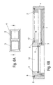
- FIGS. 5A and 5B the sliding door is shown in a closed position, in which on one side of the frame 4, the fixed field 2 and on the other side of the sliding sash 3 is arranged.
- the sliding leaf 3 covers an opening 16 which is formed within the frame 5.
- the frame has an outer side 14, which is aligned with an outer side 15 of the frame 4 and an outer side of the fixed field 2.
- the seal 8 between the frame 5 and the frame 4 or the post 19 is compressed more strongly in the closed position than the seal 11 between the frame 5 and the sliding leaf.
- the seal 8 acts as an elastic spring element which lifts the frame 5 far enough from the sliding leaf 3 that there is no longer any contact between the seal 11 and the sliding leaf 3.
- one or more spring elements can be provided for lifting the frame 5, biasing the frame 5 in the raised position.
- the frame 5 with the strips 50, 51, 52 and 53 is lifted off the sliding sash 3.
- corresponding fitting parts are provided between the frame 4 and the frame 5 and a central post 19 and the strip 53, for example a lever mechanism, a pivotable hook or a curved guide.
- the fitting parts can be moved via an actuating handle, for example a rotary handle, which is arranged on the sliding leaf 3 or on the frame 4.
- the frame 5 can be lifted off the sliding sash 3, as shown in FIGS Figures 6A and 6B is shown.
- the seal 11 is disengaged from the sliding wing 3, so that it is no longer held by the seal 11 in the closed position.
- the seal 8 can optionally also from the contact surface 17 of the post 19 or of the frame to be lifted off the frame 4 or still abut the contact surfaces. In any case, the seal has been interrupted because air can pass through the opening 16 of the frame and the sliding sash 3 into the interior.
- the frame 5 may be held in the raised position by a latching mechanism.
- the sliding leaf 3 can now be moved linearly along the guide rail without making a movement perpendicular to the plane of the sliding leaf 3 or raising the sliding leaf 3.
- the open position is shown in which the sliding panel 3 covers the fixed field 2 and an opening 16 is released within the frame 5.
- the frame 5 is moved as a unit.
- the individual strips 50, 51, 52 and 53 separately and then to lift them over individual mechanisms of the sliding leaf 3 or to move to this.
- the movement of the frame 5 may be a pure horizontal movement perpendicular to the plane of the sliding sash 3.
- the frame 5 or the individual strips 50, 51, 52 and 53 to pivot relative to the sliding sash 3 to lift the circumferentially arranged seal 8 of the sliding sash 3.
- the seals 8 and 11 are fixed to the frame 5 and are moved with this. It is of course also possible to fix the seal 8 on the sliding leaf 3 and / or the seal 11 on the frame 4 or the post 19th
Landscapes
- Engineering & Computer Science (AREA)
- Civil Engineering (AREA)
- Structural Engineering (AREA)
- Specific Sealing Or Ventilating Devices For Doors And Windows (AREA)
Applications Claiming Priority (1)
| Application Number | Priority Date | Filing Date | Title |
|---|---|---|---|
| DE201310109272 DE102013109272A1 (de) | 2013-08-27 | 2013-08-27 | Schiebetür und Verfahren zum Öffnen und Schließen einer Schiebetür |
Publications (1)
| Publication Number | Publication Date |
|---|---|
| EP2843174A1 true EP2843174A1 (fr) | 2015-03-04 |
Family
ID=51260716
Family Applications (1)
| Application Number | Title | Priority Date | Filing Date |
|---|---|---|---|
| EP14179497.4A Withdrawn EP2843174A1 (fr) | 2013-08-27 | 2014-08-01 | Porte coulissante et procédé d'ouverture et de fermeture d'une porte coulissante |
Country Status (2)
| Country | Link |
|---|---|
| EP (1) | EP2843174A1 (fr) |
| DE (1) | DE102013109272A1 (fr) |
Families Citing this family (2)
| Publication number | Priority date | Publication date | Assignee | Title |
|---|---|---|---|---|
| US10982477B2 (en) | 2017-06-09 | 2021-04-20 | Endura Products, Llc | Sliding door unit and components for the same |
| CA3087386A1 (fr) | 2019-07-18 | 2021-01-18 | Endura Products, Llc | Procedes d'actionnement d'une serrure |
Citations (2)
| Publication number | Priority date | Publication date | Assignee | Title |
|---|---|---|---|---|
| GB2206917A (en) * | 1987-06-26 | 1989-01-18 | Blohm Voss Ag | Door or hatch cover |
| EP1959080A2 (fr) | 2007-02-15 | 2008-08-20 | HAUTAU GmbH | Butée de battant mobile de fenêtre ou de porte |
-
2013
- 2013-08-27 DE DE201310109272 patent/DE102013109272A1/de active Pending
-
2014
- 2014-08-01 EP EP14179497.4A patent/EP2843174A1/fr not_active Withdrawn
Patent Citations (2)
| Publication number | Priority date | Publication date | Assignee | Title |
|---|---|---|---|---|
| GB2206917A (en) * | 1987-06-26 | 1989-01-18 | Blohm Voss Ag | Door or hatch cover |
| EP1959080A2 (fr) | 2007-02-15 | 2008-08-20 | HAUTAU GmbH | Butée de battant mobile de fenêtre ou de porte |
Also Published As
| Publication number | Publication date |
|---|---|
| DE102013109272A1 (de) | 2015-03-05 |
Similar Documents
| Publication | Publication Date | Title |
|---|---|---|
| DE20013512U1 (de) | Sektionalhub- oder Falttor | |
| DE202008018448U1 (de) | Parallel abstellbarer Beschlag für einen Schiebeflügel eines Fensters oder einer Tür | |
| EP1312743B1 (fr) | Dispositif de blocage pour un vantail coulissant et levant; ferrure du type crémone avec un tel dispositif; porte ou fenêtre coulissante et levante avec un tel dispositif | |
| DE202009014785U1 (de) | Schiebetür | |
| AT512896B1 (de) | Schiebefenster, Schiebetür od. dgl. und Dichtvorrichtung hiefür | |
| DE202014000876U1 (de) | Beschlag eines zumindest hebbaren, vorzugsweise aber auch verschiebbaren Flügels von Fenstern oder Türen | |
| WO2016026876A1 (fr) | Mécanisme d'actionnement, notamment serrure, actionnant une tringle d'une crémone pour un vantail de fenêtre ou de porte pouvant être soulevé et déplacé | |
| DE102012202986A1 (de) | Beschlag für eine Schiebetür oder ein Schiebefenster | |
| DE102017101555A1 (de) | Hubschwelle | |
| DE69328827T2 (de) | Schiebefenster, bestehend aus mindestens einem rahmen mit einem darin vertikal verschiebbaren flügel | |
| EP2157898B1 (fr) | Porte coulissante et paroi de douche à porte coulissante | |
| EP2843174A1 (fr) | Porte coulissante et procédé d'ouverture et de fermeture d'une porte coulissante | |
| DE102019211790A1 (de) | Barrierefreies Schiebefenster, barrierefreie Schiebetür sowie untere Beschlaganordnung | |
| DE102016113085B4 (de) | Wasserdichte Sektionaltor-Vorrichtung | |
| DE102015211980B4 (de) | Verschlussvorrichtung für ein ein- oder mehrteiliges Tor | |
| EP3728778B1 (fr) | Vantail de porte doté d'un système d'étanchéité | |
| WO2018046285A1 (fr) | Dispositif anti-soulèvement pour un battant déplaçable et pouvant être soulevé pour être déplacé | |
| DE102023117279A1 (de) | Schiebetüranordnung | |
| DE102017101553A1 (de) | Hebeschwelle | |
| EP3425149A1 (fr) | Construction levante-coulissante, notamment porte levante-coulissante ou fenêtre levante-coulissante | |
| DE202016002366U1 (de) | Beschlag zweier zumindest hebbarer und verschiebbarer Flügel von Fenstern oder Türen | |
| EP4421285B1 (fr) | Porte coulissante avec un battant coulissant verrouillable | |
| DE102016114965B4 (de) | Horizontal öffnendes Rolltor | |
| DE102014111301B4 (de) | Wasserdichte schwingtor-vorrichtung | |
| DE102023125043B4 (de) | System zum Öffnen einer Öffnung einer Tür |
Legal Events
| Date | Code | Title | Description |
|---|---|---|---|
| 17P | Request for examination filed |
Effective date: 20140801 |
|
| AK | Designated contracting states |
Kind code of ref document: A1 Designated state(s): AL AT BE BG CH CY CZ DE DK EE ES FI FR GB GR HR HU IE IS IT LI LT LU LV MC MK MT NL NO PL PT RO RS SE SI SK SM TR |
|
| AX | Request for extension of the european patent |
Extension state: BA ME |
|
| PUAI | Public reference made under article 153(3) epc to a published international application that has entered the european phase |
Free format text: ORIGINAL CODE: 0009012 |
|
| R17P | Request for examination filed (corrected) |
Effective date: 20150825 |
|
| RBV | Designated contracting states (corrected) |
Designated state(s): AL AT BE BG CH CY CZ DE DK EE ES FI FR GB GR HR HU IE IS IT LI LT LU LV MC MK MT NL NO PL PT RO RS SE SI SK SM TR |
|
| RAP1 | Party data changed (applicant data changed or rights of an application transferred) |
Owner name: HAUTAU GMBH |
|
| STAA | Information on the status of an ep patent application or granted ep patent |
Free format text: STATUS: REQUEST FOR EXAMINATION WAS MADE |
|
| STAA | Information on the status of an ep patent application or granted ep patent |
Free format text: STATUS: THE APPLICATION IS DEEMED TO BE WITHDRAWN |
|
| 18D | Application deemed to be withdrawn |
Effective date: 20210302 |