EP2843378B1 - Machine de travail dotée d'un dispositif de levage et d'un dispositif de pesée - Google Patents
Machine de travail dotée d'un dispositif de levage et d'un dispositif de pesée Download PDFInfo
- Publication number
- EP2843378B1 EP2843378B1 EP14155760.3A EP14155760A EP2843378B1 EP 2843378 B1 EP2843378 B1 EP 2843378B1 EP 14155760 A EP14155760 A EP 14155760A EP 2843378 B1 EP2843378 B1 EP 2843378B1
- Authority
- EP
- European Patent Office
- Prior art keywords
- payload
- boom
- pivot axis
- ausleger
- attachment
- Prior art date
- Legal status (The legal status is an assumption and is not a legal conclusion. Google has not performed a legal analysis and makes no representation as to the accuracy of the status listed.)
- Not-in-force
Links
Images
Classifications
-
- G—PHYSICS
- G01—MEASURING; TESTING
- G01G—WEIGHING
- G01G19/00—Weighing apparatus or methods adapted for special purposes not provided for in the preceding groups
- G01G19/08—Weighing apparatus or methods adapted for special purposes not provided for in the preceding groups for incorporation in vehicles
- G01G19/083—Weighing apparatus or methods adapted for special purposes not provided for in the preceding groups for incorporation in vehicles lift truck scale
-
- E—FIXED CONSTRUCTIONS
- E02—HYDRAULIC ENGINEERING; FOUNDATIONS; SOIL SHIFTING
- E02F—DREDGING; SOIL-SHIFTING
- E02F9/00—Component parts of dredgers or soil-shifting machines, not restricted to one of the kinds covered by groups E02F3/00 - E02F7/00
- E02F9/26—Indicating devices
- E02F9/264—Sensors and their calibration for indicating the position of the work tool
Definitions
- the invention relates to a work machine with a lifting device for lifting and lowering a payload and with a weighing device for weighing the payload and a method for weighing a payload.
- the lifting device for example the front loader
- the lifting device is always moved into the same weighing position after the payload has been picked up, or the same weighing position is traveled through at a specific speed and the payload is determined on the basis of a pressure measurement in the hydraulic devices.
- This is possible because the same geometric conditions prevail in this weighing position, so that the payload can be calculated using the known lever ratios and the specific hydraulic pressure.
- the requirement to always move to a weighing position or to have to travel through a weighing position at a certain speed is time-consuming and, moreover, measurement inaccuracies occur, at least when the tractor is not completely level, as a result of shifting the center of gravity.
- Slightly more complex systems have been expanded to include an inclination sensor that at least corrects a measurement error on inclined planes.
- the DE 10 2009 051 210 A1 describes a weighing device for a lifting device, in which a sensor on the lifting device detects an angular position of the lifting device. As a result, the payload can be determined in different positions during a lifting movement.
- the object of the present invention is to provide a further improved weighing device and a method for weighing a payload.
- the object is achieved by a work machine according to claim 1 and a method according to claim 6.
- the payload received via the attachment element determinable.
- the weight of the payload can advantageously be determined using an open kinematic chain.
- the sensor device has an acceleration sensor which is functionally coupled to the at least first cantilever element, in order to provide the acceleration signal as a function of an acceleration acting on the first cantilever element.
- the torque of the mass m boom about the pivot axis Y 1 can be determined from the acceleration signal and the mass m boom of the first boom element.
- the sensor device has an acceleration sensor which is functionally coupled to the attachment element in order to detect a relative movement of the attachment element relative to the extension element about the pivot axis Y 2 .
- the torque of the mass m mounting about the pivot axis Y 2 can be determined from the acceleration signal and the mass m mounting of the mounting element.
- This form of calculation offers the highest accuracy in determining the payload for dynamic weighing.
- a payload can be set approximately the same as an attachment . Since J payload has little impact on m L , J payload can be estimated for simplicity.
- Masses and centers of gravity on the components are constant as long as the structure is not changed.
- An exception is the cylinder, which contains different oil volumes depending on the position.
- the moments of inertia J only relate to the Y main axis of inertia of the components, i.e. without the Steiner component.
- Other components that must be taken into account are the hydraulic actuating cylinders and the components on the four-bar linkage. Depending on the direction of acceleration in the component's center of gravity, these components produce a positive or negative torque in the respective joints.
- only one acceleration signal is used.
- the acceleration signal of the chassis of the work machine Since the knowledge of the angular velocities ⁇ , the angular accelerations ⁇ , the kinematics and the movement of the cantilever element and the movement of the add-on element can be used to calculate the accelerations in the respective component focal points. In order to minimize deviations, however, it is advantageous to measure directly or at least close to the same component in the component focus.
- the lifting device has at least a second second boom element which is pivotally arranged on the first boom element about a third pivot axis Y 3 , the add-on element being pivotably arranged on the second boom element about the second pivot axis Y 2 .
- the object is also achieved by a method for weighing a payload picked up by a working machine with a lifting device for lifting and lowering a payload and with a weighing device for weighing the payload, in which the first force signal, the second force signal and the acceleration signal are transmitted via the Attachment payload is determined.
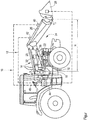
- the figure shows an agricultural machine 10 in the form of a tractor with a lifting device 12 in the form of a front loader and a weighing device 14.
- the front loader 12 is detachably coupled to the tractor 10 via a bracket 18 connected to a frame 16 of the tractor 10.
- the front loader 12 has a boom element 20 in the form of a rocker arm, which is articulated on the bracket 18 about a pivot axis Y 1 via a first actuating device 22 in the form of a hydraulic cylinder.
- an add-on element 28 in the form of a loader shovel is detachably fastened, which can be pivoted to the rocker arm via a second actuating device 26 in the form of a hydraulic cylinder and a pivot axis Y 2 20 is articulated.
- the loader bucket 28 is detachably attached to a tool holder of the rocker arm 20, not shown.
- the tractor 10 has a sensor device 24 which has a first acceleration sensor 30 in the region of the console 18.
- the acceleration sensor 30 can be designed as a 3-axis gyroscope.
- the acceleration sensor 30 can be arranged in the area of the frame 16 of the tractor 10.
- the sensor device 24 has a second acceleration sensor 32 in the area of the rocker 20.
- the acceleration sensor 32 can also be designed as a 3-axis gyroscope.
- the sensor device 24 has a third acceleration sensor 34 in the area of the loader bucket 28.
- the acceleration sensor 34 can also be designed as a 3-axis gyroscope.
- the working machine according to the invention can be equipped with the lifting device and the weighing device with only the first acceleration sensor 30 in order to carry out the weighing method according to the invention.
- the hydraulic cylinder 22 is equipped with a first pressure sensor 36 on the piston side and with a second pressure sensor 38 on the cylinder side.
- the hydraulic cylinder 26 is equipped with a third pressure sensor 40 on the piston side and with a second pressure sensor 42 on the cylinder side.
- a hydraulic flow for operating the hydraulic cylinders 22, 26 can be regulated via switching valves (not shown).
- the sensor device 24 further comprises an electronic control unit 44 which is connected to an operating lever 46, for example in the form of a joystick.
- the operating lever 46 enables an operator to enter control commands for operating the lifting device 12.
- the control unit 44 is connected via sensor lines 48 to the acceleration sensors 30, 32, 34, to the pressure sensors 36, 38, 40 and via control lines (not shown) to the likewise not shown Switching valves connected. Also not shown are the hydraulic pump and hydraulic reservoir required to supply the hydraulic cylinders 22, 26.
- a bus system (not shown) can be provided.
- the weight of a payload m L is determined using an open kinematic chain.
- the torque is continuously measured for each joint.
- the forces in the center of gravity are calculated for the individual links of the kinematic chain — in the present exemplary embodiment, the rocker arm 20 and the loader blade 28 — using measured accelerations.
- the resulting torque about the respective pivot axis Y 1 , Y 2 is calculated using the forces and the vector from the respective pivot axis Y 1 , Y 2 to the center of gravity.
Landscapes
- Engineering & Computer Science (AREA)
- Mining & Mineral Resources (AREA)
- Civil Engineering (AREA)
- General Engineering & Computer Science (AREA)
- Structural Engineering (AREA)
- Physics & Mathematics (AREA)
- General Physics & Mathematics (AREA)
- Component Parts Of Construction Machinery (AREA)
- Operation Control Of Excavators (AREA)
Claims (6)
- Machine de travail (10) comprenant un dispositif de levage (12) destiné à soulever et abaisser une charge utile (mL) et un moyen de pesage (14) destiné à peser la charge utile (mL), le dispositif de levage (12) comportant au moins un premier élément formant flèche (20) disposé au niveau d'un élément formant cadre (16) de la machine de travail (10) de façon à pouvoir pivoter sur un premier axe de pivotement (Y1) et un élément de montage (28) disposé au niveau de l'au moins un premier élément formant flèche (20) de façon à pouvoir pivoter sur un deuxième axe de pivotement (Y2) et destiné à recevoir la charge utile (mL), les premier et deuxième axes de pivotement (Y1, Y2) étant parallèles l'un à l'autre,
le dispositif de levage (12) comportant un premier dispositif d'actionnement (22) destiné à déplacer le premier élément formant flèche (20) et un deuxième dispositif d'actionnement (26) destiné à déplacer l'élément de montage (28),
le moyen de pesage (14) comportant un dispositif de détection (24) couplé fonctionnellement au dispositif de levage (12) et destiné à délivrer un premier signal de force en fonction d'une première force appliquée par le premier dispositif d'actionnement (22), délivrer en outre un deuxième signal de force en fonction d'une deuxième force appliquée par le deuxième dispositif d'actionnement (26), délivrer en outre un signal d'accélération en fonction d'une accélération agissant sur l'élément formant cadre (16) de la machine de travail (10),
une unité de commande électronique (24) déterminant la charge utile (mL), reçue par le biais de l'élément de montage (28), à partir du premier signal de force, du deuxième signal de force et du signal d'accélération,
le moyen de détection (24) comportant un capteur d'accélération (32) couplé fonctionnellement à l'au moins premier élément formant flèche (20) et destiné à délivrer le signal d'accélération en fonction d'une accélération agissant sur le premier élément formant flèche (20), et comportant
un capteur d'accélération (34) couplé fonctionnellement à l'élément de montage (28) et destiné à détecter un mouvement relatif de l'élément de montage (28) par rapport à l'élément formant flèche (20) sur l'axe de pivotement (Y2). - Machine de travail (10) selon la revendication 1, la charge utile (mL) reçue par l'élément de montage (28) pouvant être déterminée par comparaison des couples, calculés par le biais des premier et deuxième signaux de force, autour des axes de pivotement Y1 et Y2 et des couples, calculés par le biais du signal d'accélération, autour des axes pivotants Y1 et Y2.
- Machine de travail (10) selon la revendication 1 ou 2, les valeurs- longueur (rN) du premier élément formant flèche dans une direction perpendiculaire à l'axe de pivotement Y1,- masse (mflêche) du premier élément formant flèche,- centre de gravité (rCDGflèche) de la masse (mflèche) par rapport à l'axe de pivotement (Y1),- masse (mmontage) de l'élément de montage,- centre de gravité (rCOGmontage) de la masse (mmontage) par rapport à l'axe de pivotement (Y2)étant stockées dans le moyen de pesage (14) pour déterminer la charge utile (mL).
- Machine de travail (10) selon la revendication 1, la charge utile (mL) reçue via l'élément de montage (28) pouvant être déterminée de manière approchée par la formule
 mL :la masse de la charge utile TQ1, TQ2 : le couple autour de l'axe de pivotement Y1 ou Y2,avéhicule, aflèche, amontage : les accélérations de la flèche ou du montage,Jflèche, Jmontage, Jcharge utile : les moments d'inertie de la flèche, du montage ou de la charge utile,véhicule,
 flèche,montage : l'accélération angulaire du véhicule, de la flèche ou de la charge utile.
 - Machine de travail selon l'une des revendications 1 à 4, le dispositif de levage (12) comportant au moins un deuxième élément formant flèche disposé au niveau du premier élément formant flèche (20) de manière à pouvoir pivoter sur un troisième axe de pivotement (Y3), l'élément de montage () étant disposé au niveau du deuxième élément formant flèche de manière à pouvoir pivoter sur le deuxième axe de pivotement (Y2) .
- Procédé de pesage d'une charge utile (ML) reçue par une machine de travail (10) comprenant un dispositif de levage (12) destiné à soulever et abaisser une charge utile (mL) et un moyen de pesage (14) destiné à peser la charge utile (mL) selon l'une des revendications précédentes, procédé dans lequel la charge utile (mL) reçue par l'élément de montage (28) est déterminée à partir du premier signal de force, du deuxième signal de force et du signal d'accélération.
Applications Claiming Priority (1)
| Application Number | Priority Date | Filing Date | Title |
|---|---|---|---|
| DE102013203826.7A DE102013203826A1 (de) | 2013-03-06 | 2013-03-06 | Arbeitsmaschine mit Hubvorrichtung und Wiegeeinrichtung |
Publications (2)
| Publication Number | Publication Date |
|---|---|
| EP2843378A1 EP2843378A1 (fr) | 2015-03-04 |
| EP2843378B1 true EP2843378B1 (fr) | 2020-04-01 |
Family
ID=50156578
Family Applications (1)
| Application Number | Title | Priority Date | Filing Date |
|---|---|---|---|
| EP14155760.3A Not-in-force EP2843378B1 (fr) | 2013-03-06 | 2014-02-19 | Machine de travail dotée d'un dispositif de levage et d'un dispositif de pesée |
Country Status (2)
| Country | Link |
|---|---|
| EP (1) | EP2843378B1 (fr) |
| DE (1) | DE102013203826A1 (fr) |
Families Citing this family (15)
| Publication number | Priority date | Publication date | Assignee | Title |
|---|---|---|---|---|
| US10053838B2 (en) | 2016-03-04 | 2018-08-21 | Deere & Company | Coupler load measurement for work vehicle |
| DE102018216372A1 (de) | 2018-09-25 | 2020-03-26 | Deere & Company | Verfahren zum Abladen einer Nutzlast |
| DE102018216369A1 (de) | 2018-09-25 | 2020-03-26 | Deere & Company | Verfahren zum Auskippen einer Nutzlast |
| US11536009B2 (en) | 2019-07-26 | 2022-12-27 | Deere & Company | System for detecting locking pin engagement of an implement |
| US11421399B2 (en) | 2019-10-31 | 2022-08-23 | Deere & Company | Load sensitive ride system for a vehicle |
| US11441293B2 (en) | 2019-10-31 | 2022-09-13 | Deere & Company | Adjustable ride control system |
| US11136744B2 (en) | 2019-10-31 | 2021-10-05 | Deere & Company | Vehicles with control systems to perform various functions based on payload weight and methods of operating the same |
| USD931909S1 (en) | 2020-02-04 | 2021-09-28 | Deere & Company | Implement connection system |
| US11891772B2 (en) | 2021-03-29 | 2024-02-06 | Joy Global Surface Mining Inc | System and method for estimating a payload of an industrial machine |
| DE102021205407A1 (de) | 2021-05-27 | 2022-12-01 | Robert Bosch Gesellschaft mit beschränkter Haftung | Verfahren zur Beladungsschätzung von Arbeitsmaschinen |
| DE102021119455A1 (de) | 2021-07-27 | 2023-02-02 | Liebherr-France Sas | Verfahren zur Überwachung und/oder Durchführung einer Bewegung eines Arbeitsgeräts sowie Arbeitsgerät und Computerprogrammprodukt |
| CN115506429B (zh) * | 2022-09-27 | 2023-08-25 | 四川鼎鸿智电装备科技有限公司 | 一种工程机械称重方法及装置、电子设备、介质 |
| US12398529B2 (en) | 2022-10-20 | 2025-08-26 | Deere & Company | Loader latching assist method and apparatus |
| EP4600105A1 (fr) | 2024-02-08 | 2025-08-13 | Deere & Company | Procédé de sortie d'une information d'état de direction |
| EP4640953A1 (fr) | 2024-04-25 | 2025-10-29 | Deere & Company | Procédé d'adaptation de la caractéristique de fonctionnement et/ou d'actionnement d'une commande de chargeur frontal |
Citations (1)
| Publication number | Priority date | Publication date | Assignee | Title |
|---|---|---|---|---|
| DE19901563A1 (de) * | 1999-01-16 | 2000-07-27 | Pfreundt Gmbh & Co Kg | Anordnung zum Wiegen von Nutzlasten |
Family Cites Families (4)
| Publication number | Priority date | Publication date | Assignee | Title |
|---|---|---|---|---|
| DE10138974A1 (de) * | 2000-08-30 | 2002-04-18 | Caterpillar Inc | Verfahren und Vorrichtung zur Bestimmung eines Gewichtes einer Nutzlast |
| FI115162B (fi) * | 2002-07-02 | 2005-03-15 | Plustech Oy | Järjestelmä kuormien punnitsemiseksi nosto- ja siirtolaitteessa |
| DE102007045846A1 (de) * | 2007-09-26 | 2009-04-02 | Deere & Company, Moline | Landwirtschaftliche Maschine und Verfahren zur Positionsbestimmung |
| DE102009051210A1 (de) | 2009-10-29 | 2011-05-05 | Josef Fliegl | Arbeitsmaschine mit Wiegeeinrichtung |
-
2013
- 2013-03-06 DE DE102013203826.7A patent/DE102013203826A1/de not_active Ceased
-
2014
- 2014-02-19 EP EP14155760.3A patent/EP2843378B1/fr not_active Not-in-force
Patent Citations (1)
| Publication number | Priority date | Publication date | Assignee | Title |
|---|---|---|---|---|
| DE19901563A1 (de) * | 1999-01-16 | 2000-07-27 | Pfreundt Gmbh & Co Kg | Anordnung zum Wiegen von Nutzlasten |
Also Published As
| Publication number | Publication date |
|---|---|
| EP2843378A1 (fr) | 2015-03-04 |
| DE102013203826A1 (de) | 2014-09-11 |
Similar Documents
| Publication | Publication Date | Title |
|---|---|---|
| EP2843378B1 (fr) | Machine de travail dotée d'un dispositif de levage et d'un dispositif de pesée | |
| DE112009001466B4 (de) | Neigungsmesser-Messsystem und Verfahren zur Korrektur von bewegungsinduzierten Beschleunigungsfehlern | |
| DE112016000013B4 (de) | Steuersystem für ein Arbeitsfahrzeug, Steuerverfahren und Arbeitsfahrzeug | |
| DE112012003346B4 (de) | Arbeitsmaschine | |
| EP2422018B1 (fr) | Engin de chantier mobile équipé d'un dispositif de régulation de position d'un bras de travail et procédé pour réguler la position d'un bras de travail d'un engin de chantier mobile | |
| EP2042276B1 (fr) | Machine agricole et procédé de détermination de position | |
| DE102009037880B4 (de) | Mobile Arbeitsmaschine mit einer Regelvorrichtung mit einem Arbeitsarm und Verfahren zur Arbeitspunktregelung eines Arbeitsarms einer mobilen Arbeitsmaschine | |
| DE112015000241B4 (de) | Arbeitsfahrzeuge und Verfahren zum Erfassen des Kippwinkels | |
| DE112016000070B4 (de) | Arbeitsmaschinensteuersystem, arbeitsmaschine und arbeitsmaschinensteuerverfahren | |
| DE112016000152T5 (de) | Anzeigesystem einer Arbeitsmaschine und Arbeitsmaschine | |
| DE112015000179T5 (de) | Arbeitsmaschine und Verfahren zum Korrigieren eines Arbeitsausrüstungs-Parameters für die Arbeitsmaschine | |
| EP4130394B1 (fr) | Procédé de surveillance et/ou de mise en uvre d'un déplacement d'un appareil de travail, ainsi qu'appareil de travail et produit programme informatique | |
| DE112016000090T5 (de) | Baumaschinensteuerungssystem, baumaschine und baumaschinensteuerungsverfahren | |
| EP1467031A1 (fr) | Engin de travaux publics, en particulier excavatrice avec bras de godet télescopique | |
| EP2421791B1 (fr) | Machine de travail mobile présentant un accéléromètre | |
| EP3315926A1 (fr) | Procédé de détermination d'une force pondérale d'une charge utile pour un véhicule utilitaire | |
| DE102019123251A1 (de) | Systeme und verfahren zum kalibrieren eines beschleunigungssensors unter verwendung eines nutzlastsystems | |
| WO2013013821A1 (fr) | Dispositif de commande | |
| DE102021106425A1 (de) | Systeme und verfahren zum bestimmen eines standortwerts einer last in verbindung mit einem gerät | |
| DE112021003917T5 (de) | Beladearbeit-unterstützungssystem | |
| DE102005025536A1 (de) | Mobile Arbeitsmaschinen, insbesondere hydraulisch angetriebene Erdbaumaschinen, und Verfahren zur Erd- und Schüttgutbewegung | |
| DE112023002783T5 (de) | Steuervorrichtung für bagger | |
| EP1416095B1 (fr) | Véhicule de travail, en particulier une pelle rétro et/ou un véhicule avec un chargeur frontal | |
| DE112022000038T5 (de) | Verfahren zur Schätzung eines Moments eines Arbeitsgerätes | |
| DE112023004670T5 (de) | Automatisches steuerungssystem für eine arbeitsmaschine und steuerverfahren für die arbeitsmaschine |
Legal Events
| Date | Code | Title | Description |
|---|---|---|---|
| 17P | Request for examination filed |
Effective date: 20140219 |
|
| AK | Designated contracting states |
Kind code of ref document: A1 Designated state(s): AL AT BE BG CH CY CZ DE DK EE ES FI FR GB GR HR HU IE IS IT LI LT LU LV MC MK MT NL NO PL PT RO RS SE SI SK SM TR |
|
| AX | Request for extension of the european patent |
Extension state: BA ME |
|
| PUAI | Public reference made under article 153(3) epc to a published international application that has entered the european phase |
Free format text: ORIGINAL CODE: 0009012 |
|
| R17P | Request for examination filed (corrected) |
Effective date: 20150904 |
|
| RBV | Designated contracting states (corrected) |
Designated state(s): AL AT BE BG CH CY CZ DE DK EE ES FI FR GB GR HR HU IE IS IT LI LT LU LV MC MK MT NL NO PL PT RO RS SE SI SK SM TR |
|
| STAA | Information on the status of an ep patent application or granted ep patent |
Free format text: STATUS: EXAMINATION IS IN PROGRESS |
|
| 17Q | First examination report despatched |
Effective date: 20190327 |
|
| RIC1 | Information provided on ipc code assigned before grant |
Ipc: E02F 9/26 20060101ALI20190807BHEP Ipc: G01G 19/08 20060101AFI20190807BHEP |
|
| GRAP | Despatch of communication of intention to grant a patent |
Free format text: ORIGINAL CODE: EPIDOSNIGR1 |
|
| STAA | Information on the status of an ep patent application or granted ep patent |
Free format text: STATUS: GRANT OF PATENT IS INTENDED |
|
| INTG | Intention to grant announced |
Effective date: 20191030 |
|
| GRAS | Grant fee paid |
Free format text: ORIGINAL CODE: EPIDOSNIGR3 |
|
| GRAA | (expected) grant |
Free format text: ORIGINAL CODE: 0009210 |
|
| STAA | Information on the status of an ep patent application or granted ep patent |
Free format text: STATUS: THE PATENT HAS BEEN GRANTED |
|
| AK | Designated contracting states |
Kind code of ref document: B1 Designated state(s): AL AT BE BG CH CY CZ DE DK EE ES FI FR GB GR HR HU IE IS IT LI LT LU LV MC MK MT NL NO PL PT RO RS SE SI SK SM TR |
|
| REG | Reference to a national code |
Ref country code: GB Ref legal event code: FG4D Free format text: NOT ENGLISH |
|
| REG | Reference to a national code |
Ref country code: AT Ref legal event code: REF Ref document number: 1251965 Country of ref document: AT Kind code of ref document: T Effective date: 20200415 Ref country code: CH Ref legal event code: EP |
|
| REG | Reference to a national code |
Ref country code: DE Ref legal event code: R096 Ref document number: 502014013877 Country of ref document: DE |
|
| REG | Reference to a national code |
Ref country code: IE Ref legal event code: FG4D Free format text: LANGUAGE OF EP DOCUMENT: GERMAN |
|
| REG | Reference to a national code |
Ref country code: FI Ref legal event code: FGE |
|
| REG | Reference to a national code |
Ref country code: SE Ref legal event code: TRGR |
|
| PG25 | Lapsed in a contracting state [announced via postgrant information from national office to epo] |
Ref country code: BG Free format text: LAPSE BECAUSE OF FAILURE TO SUBMIT A TRANSLATION OF THE DESCRIPTION OR TO PAY THE FEE WITHIN THE PRESCRIBED TIME-LIMIT Effective date: 20200701 |
|
| REG | Reference to a national code |
Ref country code: NL Ref legal event code: MP Effective date: 20200401 |
|
| REG | Reference to a national code |
Ref country code: LT Ref legal event code: MG4D |
|
| PG25 | Lapsed in a contracting state [announced via postgrant information from national office to epo] |
Ref country code: NO Free format text: LAPSE BECAUSE OF FAILURE TO SUBMIT A TRANSLATION OF THE DESCRIPTION OR TO PAY THE FEE WITHIN THE PRESCRIBED TIME-LIMIT Effective date: 20200701 Ref country code: GR Free format text: LAPSE BECAUSE OF FAILURE TO SUBMIT A TRANSLATION OF THE DESCRIPTION OR TO PAY THE FEE WITHIN THE PRESCRIBED TIME-LIMIT Effective date: 20200702 Ref country code: IS Free format text: LAPSE BECAUSE OF FAILURE TO SUBMIT A TRANSLATION OF THE DESCRIPTION OR TO PAY THE FEE WITHIN THE PRESCRIBED TIME-LIMIT Effective date: 20200801 Ref country code: CZ Free format text: LAPSE BECAUSE OF FAILURE TO SUBMIT A TRANSLATION OF THE DESCRIPTION OR TO PAY THE FEE WITHIN THE PRESCRIBED TIME-LIMIT Effective date: 20200401 Ref country code: LT Free format text: LAPSE BECAUSE OF FAILURE TO SUBMIT A TRANSLATION OF THE DESCRIPTION OR TO PAY THE FEE WITHIN THE PRESCRIBED TIME-LIMIT Effective date: 20200401 Ref country code: PT Free format text: LAPSE BECAUSE OF FAILURE TO SUBMIT A TRANSLATION OF THE DESCRIPTION OR TO PAY THE FEE WITHIN THE PRESCRIBED TIME-LIMIT Effective date: 20200817 Ref country code: NL Free format text: LAPSE BECAUSE OF FAILURE TO SUBMIT A TRANSLATION OF THE DESCRIPTION OR TO PAY THE FEE WITHIN THE PRESCRIBED TIME-LIMIT Effective date: 20200401 |
|
| PG25 | Lapsed in a contracting state [announced via postgrant information from national office to epo] |
Ref country code: HR Free format text: LAPSE BECAUSE OF FAILURE TO SUBMIT A TRANSLATION OF THE DESCRIPTION OR TO PAY THE FEE WITHIN THE PRESCRIBED TIME-LIMIT Effective date: 20200401 Ref country code: RS Free format text: LAPSE BECAUSE OF FAILURE TO SUBMIT A TRANSLATION OF THE DESCRIPTION OR TO PAY THE FEE WITHIN THE PRESCRIBED TIME-LIMIT Effective date: 20200401 Ref country code: LV Free format text: LAPSE BECAUSE OF FAILURE TO SUBMIT A TRANSLATION OF THE DESCRIPTION OR TO PAY THE FEE WITHIN THE PRESCRIBED TIME-LIMIT Effective date: 20200401 |
|
| PG25 | Lapsed in a contracting state [announced via postgrant information from national office to epo] |
Ref country code: AL Free format text: LAPSE BECAUSE OF FAILURE TO SUBMIT A TRANSLATION OF THE DESCRIPTION OR TO PAY THE FEE WITHIN THE PRESCRIBED TIME-LIMIT Effective date: 20200401 |
|
| REG | Reference to a national code |
Ref country code: DE Ref legal event code: R097 Ref document number: 502014013877 Country of ref document: DE |
|
| PG25 | Lapsed in a contracting state [announced via postgrant information from national office to epo] |
Ref country code: DK Free format text: LAPSE BECAUSE OF FAILURE TO SUBMIT A TRANSLATION OF THE DESCRIPTION OR TO PAY THE FEE WITHIN THE PRESCRIBED TIME-LIMIT Effective date: 20200401 Ref country code: RO Free format text: LAPSE BECAUSE OF FAILURE TO SUBMIT A TRANSLATION OF THE DESCRIPTION OR TO PAY THE FEE WITHIN THE PRESCRIBED TIME-LIMIT Effective date: 20200401 Ref country code: EE Free format text: LAPSE BECAUSE OF FAILURE TO SUBMIT A TRANSLATION OF THE DESCRIPTION OR TO PAY THE FEE WITHIN THE PRESCRIBED TIME-LIMIT Effective date: 20200401 Ref country code: SM Free format text: LAPSE BECAUSE OF FAILURE TO SUBMIT A TRANSLATION OF THE DESCRIPTION OR TO PAY THE FEE WITHIN THE PRESCRIBED TIME-LIMIT Effective date: 20200401 Ref country code: ES Free format text: LAPSE BECAUSE OF FAILURE TO SUBMIT A TRANSLATION OF THE DESCRIPTION OR TO PAY THE FEE WITHIN THE PRESCRIBED TIME-LIMIT Effective date: 20200401 |
|
| PLBE | No opposition filed within time limit |
Free format text: ORIGINAL CODE: 0009261 |
|
| STAA | Information on the status of an ep patent application or granted ep patent |
Free format text: STATUS: NO OPPOSITION FILED WITHIN TIME LIMIT |
|
| PG25 | Lapsed in a contracting state [announced via postgrant information from national office to epo] |
Ref country code: PL Free format text: LAPSE BECAUSE OF FAILURE TO SUBMIT A TRANSLATION OF THE DESCRIPTION OR TO PAY THE FEE WITHIN THE PRESCRIBED TIME-LIMIT Effective date: 20200401 Ref country code: SK Free format text: LAPSE BECAUSE OF FAILURE TO SUBMIT A TRANSLATION OF THE DESCRIPTION OR TO PAY THE FEE WITHIN THE PRESCRIBED TIME-LIMIT Effective date: 20200401 |
|
| 26N | No opposition filed |
Effective date: 20210112 |
|
| PG25 | Lapsed in a contracting state [announced via postgrant information from national office to epo] |
Ref country code: SI Free format text: LAPSE BECAUSE OF FAILURE TO SUBMIT A TRANSLATION OF THE DESCRIPTION OR TO PAY THE FEE WITHIN THE PRESCRIBED TIME-LIMIT Effective date: 20200401 |
|
| PG25 | Lapsed in a contracting state [announced via postgrant information from national office to epo] |
Ref country code: MC Free format text: LAPSE BECAUSE OF FAILURE TO SUBMIT A TRANSLATION OF THE DESCRIPTION OR TO PAY THE FEE WITHIN THE PRESCRIBED TIME-LIMIT Effective date: 20200401 |
|
| REG | Reference to a national code |
Ref country code: BE Ref legal event code: MM Effective date: 20210228 |
|
| PG25 | Lapsed in a contracting state [announced via postgrant information from national office to epo] |
Ref country code: LI Free format text: LAPSE BECAUSE OF NON-PAYMENT OF DUE FEES Effective date: 20210228 Ref country code: LU Free format text: LAPSE BECAUSE OF NON-PAYMENT OF DUE FEES Effective date: 20210219 Ref country code: CH Free format text: LAPSE BECAUSE OF NON-PAYMENT OF DUE FEES Effective date: 20210228 |
|
| PG25 | Lapsed in a contracting state [announced via postgrant information from national office to epo] |
Ref country code: IE Free format text: LAPSE BECAUSE OF NON-PAYMENT OF DUE FEES Effective date: 20210219 |
|
| PG25 | Lapsed in a contracting state [announced via postgrant information from national office to epo] |
Ref country code: BE Free format text: LAPSE BECAUSE OF NON-PAYMENT OF DUE FEES Effective date: 20210228 |
|
| PG25 | Lapsed in a contracting state [announced via postgrant information from national office to epo] |
Ref country code: HU Free format text: LAPSE BECAUSE OF FAILURE TO SUBMIT A TRANSLATION OF THE DESCRIPTION OR TO PAY THE FEE WITHIN THE PRESCRIBED TIME-LIMIT; INVALID AB INITIO Effective date: 20140219 |
|
| PG25 | Lapsed in a contracting state [announced via postgrant information from national office to epo] |
Ref country code: CY Free format text: LAPSE BECAUSE OF FAILURE TO SUBMIT A TRANSLATION OF THE DESCRIPTION OR TO PAY THE FEE WITHIN THE PRESCRIBED TIME-LIMIT Effective date: 20200401 |
|
| PGFP | Annual fee paid to national office [announced via postgrant information from national office to epo] |
Ref country code: AT Payment date: 20240201 Year of fee payment: 11 |
|
| PG25 | Lapsed in a contracting state [announced via postgrant information from national office to epo] |
Ref country code: MK Free format text: LAPSE BECAUSE OF FAILURE TO SUBMIT A TRANSLATION OF THE DESCRIPTION OR TO PAY THE FEE WITHIN THE PRESCRIBED TIME-LIMIT Effective date: 20200401 |
|
| PGFP | Annual fee paid to national office [announced via postgrant information from national office to epo] |
Ref country code: FI Payment date: 20240226 Year of fee payment: 11 Ref country code: DE Payment date: 20240119 Year of fee payment: 11 Ref country code: GB Payment date: 20240227 Year of fee payment: 11 |
|
| PGFP | Annual fee paid to national office [announced via postgrant information from national office to epo] |
Ref country code: SE Payment date: 20240307 Year of fee payment: 11 Ref country code: IT Payment date: 20240222 Year of fee payment: 11 Ref country code: FR Payment date: 20240226 Year of fee payment: 11 |
|
| PG25 | Lapsed in a contracting state [announced via postgrant information from national office to epo] |
Ref country code: MT Free format text: LAPSE BECAUSE OF FAILURE TO SUBMIT A TRANSLATION OF THE DESCRIPTION OR TO PAY THE FEE WITHIN THE PRESCRIBED TIME-LIMIT Effective date: 20200401 |
|
| REG | Reference to a national code |
Ref country code: DE Ref legal event code: R119 Ref document number: 502014013877 Country of ref document: DE |
|
| REG | Reference to a national code |
Ref country code: SE Ref legal event code: EUG |
|
| PG25 | Lapsed in a contracting state [announced via postgrant information from national office to epo] |
Ref country code: FI Free format text: LAPSE BECAUSE OF NON-PAYMENT OF DUE FEES Effective date: 20250219 |
|
| REG | Reference to a national code |
Ref country code: AT Ref legal event code: MM01 Ref document number: 1251965 Country of ref document: AT Kind code of ref document: T Effective date: 20250219 |
|
| PG25 | Lapsed in a contracting state [announced via postgrant information from national office to epo] |
Ref country code: AT Free format text: LAPSE BECAUSE OF NON-PAYMENT OF DUE FEES Effective date: 20250219 |
|
| GBPC | Gb: european patent ceased through non-payment of renewal fee |
Effective date: 20250219 |
|
| PG25 | Lapsed in a contracting state [announced via postgrant information from national office to epo] |
Ref country code: TR Free format text: LAPSE BECAUSE OF FAILURE TO SUBMIT A TRANSLATION OF THE DESCRIPTION OR TO PAY THE FEE WITHIN THE PRESCRIBED TIME-LIMIT Effective date: 20200401 |
|
| PG25 | Lapsed in a contracting state [announced via postgrant information from national office to epo] |
Ref country code: DE Free format text: LAPSE BECAUSE OF NON-PAYMENT OF DUE FEES Effective date: 20250902 |
|
| PG25 | Lapsed in a contracting state [announced via postgrant information from national office to epo] |
Ref country code: GB Free format text: LAPSE BECAUSE OF NON-PAYMENT OF DUE FEES Effective date: 20250219 |
|
| PG25 | Lapsed in a contracting state [announced via postgrant information from national office to epo] |
Ref country code: FR Free format text: LAPSE BECAUSE OF NON-PAYMENT OF DUE FEES Effective date: 20250228 Ref country code: IT Free format text: LAPSE BECAUSE OF NON-PAYMENT OF DUE FEES Effective date: 20250219 |