EP2843437A2 - Direction de détermination d'arrivée pour un signal radio - Google Patents
Direction de détermination d'arrivée pour un signal radio Download PDFInfo
- Publication number
- EP2843437A2 EP2843437A2 EP14182046.4A EP14182046A EP2843437A2 EP 2843437 A2 EP2843437 A2 EP 2843437A2 EP 14182046 A EP14182046 A EP 14182046A EP 2843437 A2 EP2843437 A2 EP 2843437A2
- Authority
- EP
- European Patent Office
- Prior art keywords
- radio signal
- phase angle
- program instructions
- magnitudes
- output signals
- Prior art date
- Legal status (The legal status is an assumption and is not a legal conclusion. Google has not performed a legal analysis and makes no representation as to the accuracy of the status listed.)
- Granted
Links
Images


Classifications
-
- G—PHYSICS
- G01—MEASURING; TESTING
- G01S—RADIO DIRECTION-FINDING; RADIO NAVIGATION; DETERMINING DISTANCE OR VELOCITY BY USE OF RADIO WAVES; LOCATING OR PRESENCE-DETECTING BY USE OF THE REFLECTION OR RERADIATION OF RADIO WAVES; ANALOGOUS ARRANGEMENTS USING OTHER WAVES
- G01S3/00—Direction-finders for determining the direction from which infrasonic, sonic, ultrasonic or electromagnetic waves, or particle emission, not having a directional significance, are being received
- G01S3/02—Direction-finders for determining the direction from which infrasonic, sonic, ultrasonic or electromagnetic waves, or particle emission, not having a directional significance, are being received using radio waves
- G01S3/04—Details
- G01S3/043—Receivers
-
- G—PHYSICS
- G01—MEASURING; TESTING
- G01S—RADIO DIRECTION-FINDING; RADIO NAVIGATION; DETERMINING DISTANCE OR VELOCITY BY USE OF RADIO WAVES; LOCATING OR PRESENCE-DETECTING BY USE OF THE REFLECTION OR RERADIATION OF RADIO WAVES; ANALOGOUS ARRANGEMENTS USING OTHER WAVES
- G01S3/00—Direction-finders for determining the direction from which infrasonic, sonic, ultrasonic or electromagnetic waves, or particle emission, not having a directional significance, are being received
- G01S3/02—Direction-finders for determining the direction from which infrasonic, sonic, ultrasonic or electromagnetic waves, or particle emission, not having a directional significance, are being received using radio waves
- G01S3/04—Details
- G01S3/12—Means for determining sense of direction, e.g. by combining signals from directional antenna or goniometer search coil with those from non-directional antenna
-
- G—PHYSICS
- G01—MEASURING; TESTING
- G01S—RADIO DIRECTION-FINDING; RADIO NAVIGATION; DETERMINING DISTANCE OR VELOCITY BY USE OF RADIO WAVES; LOCATING OR PRESENCE-DETECTING BY USE OF THE REFLECTION OR RERADIATION OF RADIO WAVES; ANALOGOUS ARRANGEMENTS USING OTHER WAVES
- G01S3/00—Direction-finders for determining the direction from which infrasonic, sonic, ultrasonic or electromagnetic waves, or particle emission, not having a directional significance, are being received
- G01S3/02—Direction-finders for determining the direction from which infrasonic, sonic, ultrasonic or electromagnetic waves, or particle emission, not having a directional significance, are being received using radio waves
- G01S3/14—Systems for determining direction or deviation from predetermined direction
- G01S3/16—Systems for determining direction or deviation from predetermined direction using amplitude comparison of signals derived sequentially from receiving antennas or antenna systems having differently-oriented directivity characteristics or from an antenna system having periodically-varied orientation of directivity characteristic
- G01S3/22—Systems for determining direction or deviation from predetermined direction using amplitude comparison of signals derived sequentially from receiving antennas or antenna systems having differently-oriented directivity characteristics or from an antenna system having periodically-varied orientation of directivity characteristic derived from different combinations of signals from separate antennas, e.g. comparing sum with difference
-
- H—ELECTRICITY
- H01—ELECTRIC ELEMENTS
- H01P—WAVEGUIDES; RESONATORS, LINES, OR OTHER DEVICES OF THE WAVEGUIDE TYPE
- H01P5/00—Coupling devices of the waveguide type
- H01P5/12—Coupling devices having more than two ports
- H01P5/16—Conjugate devices, i.e. devices having at least one port decoupled from one other port
- H01P5/19—Conjugate devices, i.e. devices having at least one port decoupled from one other port of the junction type
- H01P5/22—Hybrid ring junctions
- H01P5/227—90° branch line couplers
-
- H—ELECTRICITY
- H01—ELECTRIC ELEMENTS
- H01Q—ANTENNAS, i.e. RADIO AERIALS
- H01Q11/00—Electrically-long antennas having dimensions more than twice the shortest operating wavelength and consisting of conductive active radiating elements
- H01Q11/02—Non-resonant antennas, e.g. travelling-wave antenna
- H01Q11/08—Helical antennas
-
- H—ELECTRICITY
- H01—ELECTRIC ELEMENTS
- H01Q—ANTENNAS, i.e. RADIO AERIALS
- H01Q21/00—Antenna arrays or systems
- H01Q21/06—Arrays of individually energised antenna units similarly polarised and spaced apart
- H01Q21/08—Arrays of individually energised antenna units similarly polarised and spaced apart the units being spaced along or adjacent to a rectilinear path
Definitions
- the disclosed embodiments generally relate to monopulse systems, and more particularly, to monopulse systems capable of determining the physical location of a source of a radio signal.
- One known method to build a radio signal direction-finding system includes creating a single antenna with a narrow beamwidth.
- the radio source is known to be in the direction the antenna's beam is pointed to.
- a narrow beam is necessary to obtain the source's direction with good angular resolution. It is noted that an antenna's beamwidth is inversely related to its size. An antenna with a sufficiently narrow beam tends to be inconveniently large.
- Another known method of determining the direction of arrival of a radio signal is a sequential lobing technique.
- an antenna system is deployed which has two beams (also known as lobes) pointing in two different but nearby directions.
- This technique typically involves activation of the two beams alternately and sequentially on sequential radio transmissions or radar pulses.
- the signal strengths from the two beams can be compared to each other.
- the source of the radio signal is deduced to be in the direction of the stronger beam and the ratio of the strengths indicates the degree the radio signal is directed toward the stronger beam.
- the sequential lobing technique does not require especially narrow beam widths and thus the antenna(s) can be relatively small.
- a radio signal direction-finding system based on the sequential lobing technique may misinterpret these changes as the direction of arrival indication.
- a method and system for determining the direction of arrival of a radio signal in which at least two input signals characterizing a radio signal having a radio frequency (RF) are received.
- the input signals are converted into at least three output signals.
- the output signals have a unique combination of corresponding magnitudes for each RF phase difference between the input signals.
- a set of magnitudes corresponding to the output signals is measured.
- An RF phase angle value is determined based on the measured set of magnitudes.
- the RF phase angle value is converted into an angle value indicative of the direction of arrival of the radio signal.
- a computer program product for determining the direction of arrival of a radio signal.
- the computer program product comprises one or more computer-readable storage devices and a plurality of program instructions stored on at least one of the one or more computer-readable storage devices.
- the plurality of program instructions comprises program instructions to receive at least two input signals each characterizing the radio signal having a radio frequency (RF).
- the plurality of program instructions further comprises program instructions to convert the at least two input signals into at least three output signals.
- the at least three output signals have a unique combination of corresponding magnitudes for each RF phase difference between the at least two input signals.
- the plurality of program instructions further comprises program instructions to measure a set of magnitudes corresponding to the at least three output signals.
- the plurality of program instructions further comprises program instructions to determine an RF phase angle value based on the measured set of magnitudes.
- the plurality of program instructions further comprises program instructions to convert the RF phase angle value into an angle value indicative of the direction of arrival of the radio signal.
- an illustrated embodiment of the present invention in one aspect generally relates to a system for determining the physical location of a source of a radio signal using a monopulse technique.
- the monopulse technique addresses the weakness of the sequential lobing technique described above by determining the DOA data from a single radio transmission or radar pulse.
- the system illustrated in FIG. 6 measures the phase difference between signals received by at least two separated antennas and converts this difference into a unique combination of magnitudes for each possible radio frequency (RF) phase angle difference between the two received signals.
- the system further includes the DOA analyzer program (shown in FIG. 1 ) for performing DOA determination based on the unique combination of magnitude measurements.
- FIG. 1 an exemplary computer environment is illustrated in which an illustrative embodiment of the present invention may be implemented. It should be appreciated that FIG. 1 is only provided as an illustration of one implementation and is not intended to imply any limitation with regard to the environments in which different embodiments may be implemented. Many modifications to the depicted environments may be made.
- Computer system 100 is a network of computers.
- computer system 100 is the Internet with network 102 representing a worldwide collection of networks and gateways that use the Transmission Control Protocol/Internet Protocol suite of protocols to communicate with one another.
- network 102 representing a worldwide collection of networks and gateways that use the Transmission Control Protocol/Internet Protocol suite of protocols to communicate with one another.
- At the heart of the Internet is a backbone of high-speed data communication lines between major nodes or host computers consisting of thousands of commercial, governmental, educational and other computer systems that route data and messages.
- computer system 100 also may be implemented as a number of different types of networks, such as an intranet, a local area network (LAN), or a wide area network (WAN).
- Network 102 is the medium used to provide communications links between various devices and computers connected together within computer system 100.
- Network 102 may include connections, such as wire, wireless communication links, or fiber optic cables.
- Client computers 118 and 120 connect to network 102.
- Client computers 118 and 120 may be, for example, mobile devices, telephones, television receivers, cell phones, personal digital assistants, netbooks, laptop computers, tablet computers, desktop computers, and/or any type of computing devices capable of rendering DOA determination results to a user via, for example user interfaces (UIs) 126 and 128.
- UIs 126 and 128 can be, for example, graphical user interfaces (GUIs) or web user interfaces (WUIs).
- GUIs graphical user interfaces
- WUIs web user interfaces
- Server computer 106 and storage unit 122 also connect to network 102.
- Computer system 100 may include additional server computers, client computers, displays and other devices not shown.
- Client computers 118 and 120 are clients to server computer 106 in this example.
- Server computer 106 may contain an input device 108 and an output device 110.
- DOA analyzer program 130 located in computer system 100, may comprise program instructions stored on one or more computer-readable storage devices, which may include internal storage 112 on server computer 106.
- DOA analyzer program 130 may be, for example, a computer program or program component for determining the physical location of a source of a received radio signal as discussed further below in conjunction with FIG. 9 .
- Data gathered, generated, and maintained for use by DOA analyzer program 130 may be kept in internal storage 112 of server computer 106 or in one or more databases 124 of storage unit 122.
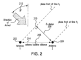
- Pair of antennas 202, 204 is separated by a distance "d" 206 so that a wave incident at an angle ⁇ 212 to the antennas 202, 204 will provide a phase difference in the electrical signals generated within the antennas 202, 204.
- the angular direction of arrival of the radio signal may be obtained by measuring angle ⁇ 212 relative to the perpendicular to a baseline 214. For purposes of illustration it is assumed that a source of the received radio signal is distant enough so that the corresponding radio wave can be modeled as approximating a plane wave.
- phase front 210 of the plane wave arrives at first antenna 202 at time t 1 . Due to the finite propagation speed, phase front 210 arrives at second antenna 204 at a later time t 2 .
- the time interval ⁇ t between t 1 and t 2 can be converted to an equivalent RF phase difference ⁇ measured between the signals received by the antennas 202, 204.
- FIG. 6 illustrates a detailed diagram of a system, which may be used for determining the DOA of the radio signal in accordance with an illustrated embodiment of the present invention.
- a DOA determination system 600 may include pair of antennas 202, 204, a phase angle measurement circuit 302, a mobile measuring device 602 and the server computer 106 of FIG. 1 .
- the server computer 106 of the computer system of FIG. 1 is depicted in FIG. 6 .
- Various components of the DOA determination system 600 will be further discussed below.
- the phase angle measurement circuit 302 takes two signals representing a radio signal received by the pair of antennas 202, 204 as input.
- the phase angle measurement circuit 302 produces a set of three outputs.
- the produced set contains a unique combination of magnitudes for each possible RF phase angle difference between the two input signals.
- the antennas 202 and 204 In response to receiving a radio signal, the antennas 202 and 204 produce RF carrier voltages V 1 and V 2 referred to herein after as a first input signal (V 1 ) 304 and second input signal (V 2 ) 306.
- the circuit 302 is configured to produce three output signals, such as, for example, first output signal (V 3 ) 308, second output signal (V 4 ) 309, and third output signal (V 5 ) 310.
- the output signals 308, 309 and 310 have individual magnitudes and phases.
- the DOA determination system 600 is concerned only with the magnitude component of output signals 308, 309 and 310.
- the phase angle measurement circuit 302 may include a phase shifting circuit component, a power splitting circuit component and a power combining circuit component.
- the phase shifting circuit component may include a quadrature hybrid 402.
- the quadrature hybrid 402 is a device which accepts two inputs, delivers up to two outputs, adjusts power levels from the inputs to the outputs in various ways, and potentially changes phase of one or both outputs.
- a first output signal 412 of the quadrature hybrid 402 may represent a sum of the first input signal 304 phase shifted by 90 degrees and the second input signal 306 phase shifted by 180 degrees.
- a second output signal 414 of the quadrature hybrid 402 may represent a sum of the first input signal 304 phase shifted by 180 degrees and the second input signal 306 phase shifted by 90 degrees.
- the power splitting circuit component may include a pair of splitters 406 and 408.
- Each of the splitters 406 and 408 may be configured for separating each of the first 412 and second 414 output signals.
- First splitter 406 produces a first pair of output signals 416 and 308 that are duplicates of the first output signal 412 of the phase shifting circuit 402.
- second splitter 408 produces a second pair of output signals 418 and 312 that are duplicates of the second output signal 414 of the phase shifting circuit 402.
- the first 406 and second 408 splitters may comprise reactive splitters consisting of a pair of quarter wavelength ( ⁇ /4) transmission line sections with characteristic impedance of approximately 70.7 ohms.
- the first 406 and second 408 splitters may be implemented as Wilkinson type splitters.
- a power combining circuit may include a Wilkinson-type power combiner 410.
- the Wilkinson combiner 410 receives one of the first pair of output signals 416 of the first splitter 406 and one of the second pair of output signals 418 of the second splitter 408.
- the Wilkinson combiner 410 generates an output signal 310 comprising a sum of the received input signals 416 and 418.
- the Wilkinson-type power combiner 410 may include a resistor since input signals 416 and 418 may differ and since a differential signal may be present in the power combining circuit.
- the phase angle measurement circuit 302 takes two input signals 304 and 306 representing a radio signal received by the pair of antennas 202, 204.
- the phase angle measurement circuit 302 produces a set of three output signals 308, 310, 312.
- First output signal 308 of the phase angle measurement circuit 302 comprises one of the output signals of the first splitter 406.
- Third output signal 312 of the phase angle measurement circuit 302 comprises one of the output signals of the second splitter 408.
- Second output signal 310 of the phase angle measurement circuit 302 comprises a previously described output from the Wilkinson-type power combiner 410.
- the produced set of output signals 308, 310, 312 comprises a unique combination of magnitudes for each possible RF phase angle difference between the two input signals 304 and 306.
- each microstrip transmission line may include a ground conductor that forms a ground plane and at least one signal line.
- transmission lines may include any suitable number of signal conductors.
- three different types of microstrip transmission lines are used.
- the quadrature hybrid 402 may be designed to operate in a system where the characteristic impedance of the interconnecting transmission lines is 50 ohms. As discussed above, the quadrature hybrid 402 may be designed to divide signal power equally at the output ports, so the medium-width shunt transmission line sections corresponding to hybrid's inputs 304, 306 and outputs 412, 414 may be designed to have approximately 50 ohm impedance.
- a wide-series transmission line section 502 may have approximately 35 ohm impedance.
- the wide-series transmission line section 502 may have a substantially ring-shaped geometry as shown in FIG. 5 .
- quadrature hybrid 402 is shown to have conventional ring shaped transmission lines, in various embodiments of the present invention other types of quadrature hybrids may be utilized, such as, for example, but not limited to coupled-line type of quadrature hybrid, broad-band hybrid, Lange hybrid and the like.
- Narrower transmission line sections forming the first 406 and second 408 splitters and the Wilkinson-type power combiner 410 may have impedance equal to approximately 70 ohms.
- the phase angle measurement circuit 302 may include a resistor (not shown in FIG. 5 ), which may have an impedance equal to approximately 100 ohms.
- the resistor may be placed across a narrow gap 504 between the inputs 416 and 418 of the Wilkinson-type power combiner 410.
- the first and second splitters 406 and 408, respectively, and Wilkinson-type power combiner 410 may be implemented as magic tee hybrids.
- the quadrature hybrid 402, first and second splitters 406 and 408, and Wilkinson-type power combiner 410 can be lumped element components.
- the illustrated DOA determination system 600 may include, for example, but not limited to, at least two circularly-polarized antennas 202 and 204 having substantially helical geometry, as shown in FIG. 6 .
- the pair of antennas 202, 204 may be connected to the phase angle measurement circuit 302, as shown in FIG. 6 .
- the three outputs 308, 310, 312 of the phase angle measurement circuit 302 may be connected to the mobile measuring device 602 via, for example, corresponding SMA connectors 604.
- the mobile measuring device 602 may be configured to measure signal power of the three output signals 308, 310, 312 generated by the phase angle measurement circuit 302.
- the mobile measuring device 602 may include a plurality of power meters capable of measuring and storing the amplitudes of the output signals 308, 310 and 312 generated by the phase angle measurement circuit 302.
- the DOA determination system 600 may include computer system 100 (shown in FIG. 1 ) consisting of one or more computers, such as server computer 106, linked via network 102.
- DOA analyzer program 130 executing at least partly on the server computer 106 may be configured to receive the measurements obtained by the mobile measuring device 602, compute the DOA angle, and transmit the calculated results to one or more client computers 118, 120.
- the client computers 118, 120 may present the calculated results to a user, using, for example, UI 126, 128.
- first antenna 202 and second antenna 204 when they receive a radio signal with a radian frequency ⁇ , they will generate first input signal ( V 1 ) 304 and second input signal ( V 2 ) 306 of the same frequency.
- the first output signal 412 of the quadrature hybrid 402 may represent a sum of the first input signal 304 phase shifted by 90 degrees and the second input signal 306 phase shifted by 180 degrees.
- first splitter 406 produces first output signal (V 3 ) 308 of the phase angle measurement circuit 302 that duplicates the first output signal 412 of the quadrature hybrid 402.
- equations (10), (11) and (12) form a non-linear system of equations (13):
- P 3 1 8 ⁇ R 0 ⁇ V 1 2 + V 2 2 - 2 V 1 ⁇ V 2 ⁇ sin ⁇
- P 4 1 8 ⁇ R 0 ⁇ V 1 2 + V 2 2 + 2 V 1 ⁇ V 2 ⁇ cos ⁇
- P 5 1 8 ⁇ R 0 ⁇ V 1 2 + V 2 2 + 2 V 1 ⁇ V 2 ⁇ sin ⁇
- the non-linear system of equations (13) produces a unique combination of power magnitudes (P 3 , P 4 and P 5 ) for each possible RF phase angle ⁇ difference between the two input signals 304 and 306.
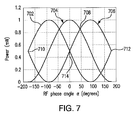
- FIG. 7 illustrates the behavior of the non-linear system of equations (13) as ⁇ is varied, for the special case of equal-magnitude input signals 304 and 306.
- the horizontal axis depicts the value of variable RF phase angle ⁇ being varied from -180 degrees to +180 degrees.
- the vertical axis of the graphs shown in FIG. 7 depicts the value of average power. It is noted that even though the input signals 304 and 306 have the same magnitude, a unique combination of magnitudes (P 3 represented by curve 702, P 4 represented by curve 704 and P 5 represented by curve 706) is produced by the phase angle measurement circuit 302 for each possible RF phase angle ⁇ . As described below with reference to FIG.
- the DOA analyzer program 130 takes advantage of this uniqueness property by reversing the relationship in order to determine RF phase angle ⁇ based on the measurements of three characteristic power magnitudes (P 3 , P 4 and P 5 ).
- FIG. 7 illustrates the power amplitude crossover points 708, 710, 712, and 714. As discussed below, these power crossover points 708, 710, 712, and 714 occur at the same angle values irrespective of the relative amplitudes of the input signals 304 and 306.
- FIG. 8 illustrates the behavior of the non-linear system of equations (13) as ⁇ is varied, for a different special case where input signals 304 and 306 differ in magnitude.
- one of the input signals for example first input signal 304, has a power magnitude of approximately 1 milliwatt and the other input signal (second input signal 306) has a power magnitude of approximately 0.1 milliwatt.
- the output power magnitude combinations produced by the phase angle measurement circuit 302 (P 3 represented by curve 802, P 4 represented by curve 804 and P 5 represented by curve 806) are still unique for different input RF phase angles ⁇ .
- FIG. 8 also illustrates the power amplitude crossover points 808, 810, 812, and 814 for this special case.
- DOA analyzer program 130 may be, for example, a computer program or program component for determining the physical location of a source of the received radio signal.
- DOA analyzer program 130 executing, for example on server computer 106, may comprise program instructions stored on one or more computer-readable storage devices, which may include internal storage 112 on server computer 106.
- DOA analyzer program 130 may be configured to receive and process the power amplitude measurements (P 3 , P 4 and P 5 ) obtained by the mobile measurement device 602, as discussed below.
- the DOA analyzer program 130 may first determine the RF phase angle ⁇ based on the received power amplitude measurements (P 3 , P 4 and P 5 ) using the non-linear system of equations (13). Next, the DOA analyzer program 130 may convert the RF phase angle ⁇ into an angle indicative of DOA.
- the DOA analyzer program 130 may receive the power amplitude measurements (P 3 , P 4 and P 5 ) from the mobile measurement device 602 (shown in FIG. 6 ). If the mobile measurement device 602 produces readings in logarithmic units, at step 901, the DOA analyzer program 130 may convert the power amplitude measurements from logarithmic units to linear units, such as, for example, but not limited to milliwatt (mW).
- mW milliwatt
- this case is expected to be relatively rare in practice because if a radio signal arrives, for example, at first antenna 202 (shown in FIG.2 ) typically second antenna 204 will receive at least a part of the same radio signal too.
- an embodiment of the present invention considers this case negligible, and the DOA analyzer program 130 considers such measurements to be invalid. Accordingly, in response to determining that the three measured power amplitudes are equal (determination block 902, yes branch), the DOA analyzer program 130 may return to step 901 and wait for a valid set of power amplitude measurements.
- the DOA analyzer program 130 may determine, at step 904, whether any two of the received three power amplitude measurements (P 3 , P 4 and P 5 ) are equal. According to an embodiment of the present invention, this determination provides a way to identify the RF phase angle ⁇ with minimal computation for the special angles corresponding to the power amplitude crossover points 708, 710, 712, 714 and 808, 810, 812, and 814 (shown in FIGs. 7 and 8 , respectively). As discussed below, the power amplitude crossover points 708-714 and 808-814 always occur at the same special angles, regardless of the relative amplitudes of the three power amplitude measurements (P 3 , P 4 and P 5 ).
- the special angles corresponding to the power amplitude crossover points 708-714 are shown.
- the special angles may include ⁇ 0 1014, ⁇ ⁇ 1 1016, ⁇ ⁇ 2 1018, and ⁇ ⁇ 3 1020.
- First special angle ⁇ 0 1014 occurs at 0° due to symmetry of the curves representing the measured power magnitudes.
- curve 702 representing power magnitude P 3 is symmetrical to curve 706 representing the power magnitude P 5
- the crossover point 714 occurs due to this symmetry.
- Second special angle ⁇ 1 1016 occurs when the power magnitude P 4 is equal to the power magnitude P 5 .
- ⁇ 1 45 ⁇ °
- third special angle ⁇ 2 1018 occurs when the power magnitude P 3 is equal to the power magnitude P 4 .
- ⁇ 2 135 ⁇ °
- Fourth special angle ⁇ 3 1020 occurs at 180° due to symmetry of the curves representing the measured power magnitudes.
- curve 702 representing power magnitude P 3 is symmetrical to curve 706 representing the power magnitude P 5 , and the crossover points 710 and 712 occur due to this symmetry.
- the DOA analyzer program 130 may identify the RF phase angle ⁇ by determining if any two of the received power amplitude measurements (P 3 , P 4 and P 5 ) are equal to each other and then determining if the third power amplitude measurement is greater than or less than the equal power amplitude measurements.
- the DOA analyzer program 130 may determine the RF phase angle ⁇ by, for example, examining Table 1 shown above.
- Table 1 may be stored in one or more databases 124 of storage unit 122 (shown in FIG. 1 ).
- Table 1 may be included, as a plurality of conditions, within programming instructions of the DOA analyzer program 130.
- the DOA analyzer program 130 may calculate the RF phase angle ⁇ using a search technique described below in connection with steps 908 and 910.
- the DOA analyzer program 130 may first reduce a scope of the search by determining an angle zone in which the RF phase angle ⁇ of interest may lie in. With reference back to FIG. 10 , a plurality of angle zones 1002-1012 is shown, the RF phase angle ⁇ is varied from -180 degrees to +180 degrees. According to an embodiment of the present invention, the DOA analyzer program 130 may determine an angle zone by comparing all of the received power amplitude measurements (P 3 , P 4 and P 5 ).
- Table 2 summarizes how the DOA analyzer program 130 may identify the angle zone based on the required comparisons: Table 2 Condition Angle Zone P 3 > P 5 > P 4 I P 3 > P 4 > P 5 II P 4 > P 3 > P 5 III P 4 > P 5 > P 3 IV P 5 > P 4 > P 3 V P 5 > P 3 > P 4 VI
- the DOA analyzer program may identify first angle zone 1002, as the angle zone in which the RF phase angle ⁇ of interest lies in.
- the DOA analyzer program may identify third angle zone 1006, as the angle zone in which the RF phase angle ⁇ of interest lies in.
- Table 2 may be stored in one or more databases 124 of storage unit 122 (shown in FIG. 1 ). According to an alternative embodiment, Table 2 may be included, as a plurality of conditional statements, within programming instructions of the DOA analyzer program 130.
- the DOA analyzer program 130 may perform calculations for the special angles corresponding to the power amplitude crossover points 708-714 at step 906, described above, those special angles are excluded from the zone they border. For instance, if the second special angle ⁇ 1 1016 is equal to 45° and the third special angle ⁇ 2 1018 is equal to 135°, then fifth angle zone 1010 may include angles from 46° to 134° inclusively. Similarly, if the second special angle ⁇ 1 1016 is equal to 45° and the first special angle ⁇ 0 1014 is equal to 0°, then fourth angle zone 1008 may include angles from 1° to 44° inclusively.
- the angle zones determined by the DOA analyzer program 130 at step 908 may be used as rough estimates of the RF phase angle ⁇ .
- the DOA analyzer program 130 may skip step 910 described below and may go to step 912 after determining the angle zone at step 908.
- the DOA analyzer program 130 may search the angle zone identified at step 908 using calculations described below.
- V 2 R 0 x 1 x 2
- the matrix equation (26) represents an over-determined set of three linear equations in two unknowns (for a specific RF phase angle ⁇ ).
- the two unknowns (x 1 and x 2 ) are the components of the column vector x (23).
- the DOA analyzer program 130 may solve the matrix equation (26) by using, for example, standard least square (LS) estimation method.
- the standard least square estimation method is generally known in the art and is not described herein in detail.
- ⁇ 1 , ⁇ 2 , ⁇ 3 are orthogonal components of vector ⁇ .
- the DOA analyzer program 130 may find the RF phase angle ⁇ by first computing the residual error ⁇ using equation (28) for each angle in a set of candidate angles within the angle zone identified by the DOA analyzer program 130 at step 908.
- set of candidate angles refers to substantially all angles contained within an angle zone spaced apart by a predetermined spacing.
- the DOA analyzer program 130 may assume that all angles in an angle zone are spaced apart by approximately 1°. Subsequently, the DOA analyzer program 130 may find the RF phase angle ⁇ by determining the candidate angle having the smallest magnitude of the residual vector ⁇ , using equation (29).
- the DOA analyzer program 130 may include an optional step of pre-camputing and pre-storing the bracketed expression ( A(A T A) -1 A-I 3 ) in equation (28) for each candidate angle in each set of candidate angles. It is noted that the aforementioned bracketed expression represents a constant 3x3 matrix for each candidate angle. By pre-computing and pre-storing the bracketed expression, the DOA analyzer program 130 may significantly reduce computation time required to determine the RF phase angle ⁇ . According to an embodiment of the present invention, the DOA analyzer program 130 may store the pre-computed bracketed expression in one or more databases 124 of storage unit 122.
- the DOA analyzer program 130 may convert the RF phase angle ⁇ into the angle ⁇ indicative of the direction of arrival of the received radio signal wave. According to an embodiment of the present invention, the DOA analyzer program 130 may utilize formula (4) above to perform the aforementioned conversion.
- illustrated embodiments of the present invention in one aspect generally relate to a system for determining the physical location of a source of a radio signal using a monopulse technique.
- the system illustrated in FIG. 6 measures the phase difference between signals received by at least two separated antennas and converts this difference into a unique combination of power magnitudes for each possible RF phase angle difference between the two received signals.
- the system further includes the DOA analyzer program 130 ( FIG. 1 ) for performing DOA determination based on the unique combination of power magnitude measurements.
- illustrated embodiments of the present invention generally require measurement of amplitude component only, but not phase. Unlike other phase-comparison monopulse systems known in the art, the system disclosed herein uses three distinct measurement channels on a single angular dimension.
- illustrated embodiments of the present invention are unaffected by various radio propagation factors, such as, for example, a significant difference in amplitude between the two signals received at the two antennas.
- the illustrated embodiments contemplate that the DOA determination system 600 may be configured to perform the DOA determination calculations for both modulated and un-modulated signals.
- the modulation may be passed on in a linear undistorted fashion.
- demodulators are included along with the plurality of power meters within the power measuring device 602, such demodulators may operate on the modulation to produce additional signal information.
- aspects of the present invention may be embodied as a system, method or computer program product. Accordingly, aspects of the present invention may take the form of an entirely hardware embodiment, an entirely software embodiment (including firmware, resident software, micro-code, etc.) or an embodiment combining software and hardware aspects that may all generally be referred to herein as a "circuit,” “module” or “system.” Furthermore, aspects of the present invention may take the form of a computer program product embodied in one or more computer readable medium(s) having computer readable program code embodied thereon.
- the computer readable medium may be a computer readable signal medium or a computer readable storage medium.
- a computer readable storage medium may be, for example, but not limited to, an electronic, magnetic, optical, electromagnetic, infrared, or semiconductor system, apparatus, or device, or any suitable combination of the foregoing.
- a computer readable storage medium may be any tangible medium that can contain, or store a program for use by or in connection with an instruction execution system, apparatus, or device.
- a computer readable signal medium may include a propagated data signal with computer readable program code embodied therein, for example, in baseband or as part of a carrier wave. Such a propagated signal may take any of a variety of forms, including, but not limited to, electro-magnetic, optical, or any suitable combination thereof.
- a computer readable signal medium may be any computer readable medium that is not a computer readable storage medium and that can communicate, propagate, or transport a program for use by or in connection with an instruction execution system, apparatus, or device.
- Program code embodied on a computer readable medium may be transmitted using any appropriate medium, including but not limited to wireless, wireline, optical fiber cable, RF, etc., or any suitable combination of the foregoing.
- Computer program code for carrying out operations for aspects of the present invention may be written in any combination of one or more programming languages, including an object oriented programming language such as Java, Smalltalk, C++ or the like and conventional procedural programming languages, such as the "C" programming language or similar programming languages.
- the program code may execute entirely on the user's computer, partly on the user's computer, as a stand-alone software package, partly on the user's computer and partly on a remote computer or entirely on the remote computer or server.
- the remote computer may be connected to the user's computer through any type of network, including a local area network (LAN) or a wide area network (WAN), or the connection may be made to an external computer (for example, through the Internet using an Internet Service Provider).
- LAN local area network
- WAN wide area network
- Internet Service Provider for example, AT&T, MCI, Sprint, EarthLink, MSN, GTE, etc.
- These computer program instructions may also be stored in a computer readable medium that can direct a computer, other programmable data processing apparatus, or other devices to function in a particular manner, such that the instructions stored in the computer readable medium produce an article of manufacture including instructions which implement the function/act specified in the flowchart and/or block diagram block or blocks.
- the computer program instructions may also be loaded onto a computer, other programmable data processing apparatus, or other devices to cause a series of operational steps to be performed on the computer, other programmable apparatus or other devices to produce a computer implemented process such that the instructions which execute on the computer or other programmable apparatus provide processes for implementing the functions/acts specified in the flowchart and/or block diagram block or blocks.
- FIG 11 illustrates internal and external components of server computer 106 in accordance with an illustrative embodiment.
- Server 106 is only one example of a suitable server computer and is not intended to suggest any limitation as to the scope of use or functionality of embodiments of the invention described herein. Regardless, server 106 is capable of being implemented and/or performing any of the functionality set forth hereinabove.
- Server 106 is operational with numerous other general purpose or special purpose computing system environments or configurations. Examples of well-known computing systems, environments, and/or configurations that may be suitable for use with computer system/server 106 include, but are not limited to, personal computer systems, server computer systems, thin clients, thick clients, hand-held or laptop devices, multiprocessor systems, microprocessor-based systems, set top boxes, programmable consumer electronics, network PCs, minicomputer systems, mainframe computer systems, and distributed data processing environments that include any of the above systems or devices, and the like.
- Server 106 may be described in the general context of computer system-executable instructions, such as program modules, being executed by a computer system.
- program modules may include routines, programs, objects, components, logic, data structures, and so on that perform particular tasks or implement particular abstract data types.
- Server 106 may be practiced in distributed data processing environments where tasks are performed by remote processing devices that are linked through a communications network.
- program modules may be located in both local and remote computer system storage media including memory storage devices.
- Server 106 is shown in FIG. 11 in the form of a general-purpose computing device.
- the components of server 106 may include, but are not limited to, one or more processors or processing units 1116, a system memory 1128, and a bus 1118 that couples various system components including system memory 1128 to processor 1116.
- Bus 1118 represents one or more of any of several types of bus structures, including a memory bus or memory controller, a peripheral bus, an accelerated graphics port, and a processor or local bus using any of a variety of bus architectures.
- bus architectures include Industry Standard Architecture (ISA) bus, Micro Channel Architecture (MCA) bus, Enhanced ISA (EISA) bus, Video Electronics Standards Association (VESA) local bus, and Peripheral Component Interconnect (PCI) bus.
- Computer server 106 typically includes a variety of computer system readable media. Such media may be any available media that is accessible by computer server 106, and it includes both volatile and non-volatile media, removable and non-removable media.
- System memory 1128 can include computer system readable media in the form of volatile memory, such as random access memory (RAM) 1130 and/or cache memory 1132.
- Computer server 106 may further include other removable/non-removable, volatile/non-volatile computer system storage media.
- storage system 1134 can be provided for reading from and writing to a non-removable, non-volatile magnetic media (not shown and typically called a "hard drive").
- a magnetic disk drive for reading from and writing to a removable, non-volatile magnetic disk (e.g., a "floppy disk")
- an optical disk drive for reading from or writing to a removable, non-volatile optical disk such as a CD-ROM, DVD-ROM or other optical media
- each can be connected to bus 1118 by one or more data media interfaces.
- memory 1128 may include at least one program product having a set (e.g., at least one) of program modules that are configured to carry out the functions of embodiments of the invention.
- Program/utility 1140 having a set (at least one) of program modules 1115, such as the DOA analyzer program 130, may be stored in memory 1128 by way of example, and not limitation, as well as an operating system, one or more application programs, other program modules, and program data. Each of the operating system, one or more application programs, other program modules, and program data or some combination thereof, may include an implementation of a networking environment.
- Program modules 1115 generally carry out the functions and/or methodologies of embodiments of the invention as described herein.
- Computer server 106 may also communicate with one or more external devices 1114 such as a keyboard, a pointing device, a display 1124, etc.; one or more devices that enable a user to interact with computer server 106; and/or any devices (e.g., network card, modem, etc.) that enable computer server 106 to communicate with one or more other computing devices. Such communication can occur via Input/Output (I/O) interfaces 1122. Still yet, computer server 106 can communicate with one or more networks such as a local area network (LAN), a general wide area network (WAN), and/or a public network (e.g., the Internet) via network adapter 1120. As depicted, network adapter 1120 communicates with the other components of computer server 106 via bus 618.
- LAN local area network
- WAN wide area network
- public network e.g., the Internet
- each block in the flowchart or block diagrams may represent a module, segment, or portion of code, which comprises one or more executable instructions for implementing the specified logical function(s).
- the functions noted in the block may occur out of the order noted in the figures. For example, two blocks shown in succession may, in fact, be executed substantially concurrently, or the blocks may sometimes be executed in the reverse order, depending upon the functionality involved.
Landscapes
- Physics & Mathematics (AREA)
- Engineering & Computer Science (AREA)
- General Physics & Mathematics (AREA)
- Radar, Positioning & Navigation (AREA)
- Remote Sensing (AREA)
- Variable-Direction Aerials And Aerial Arrays (AREA)
- Radar Systems Or Details Thereof (AREA)
Applications Claiming Priority (1)
| Application Number | Priority Date | Filing Date | Title |
|---|---|---|---|
| US13/974,327 US9581677B2 (en) | 2013-08-23 | 2013-08-23 | Direction of arrival determination for a radio signal |
Publications (3)
| Publication Number | Publication Date |
|---|---|
| EP2843437A2 true EP2843437A2 (fr) | 2015-03-04 |
| EP2843437A3 EP2843437A3 (fr) | 2015-04-08 |
| EP2843437B1 EP2843437B1 (fr) | 2016-12-28 |
Family
ID=51492163
Family Applications (1)
| Application Number | Title | Priority Date | Filing Date |
|---|---|---|---|
| EP14182046.4A Not-in-force EP2843437B1 (fr) | 2013-08-23 | 2014-08-22 | Direction de détermination d'arrivée pour un signal radio |
Country Status (4)
| Country | Link |
|---|---|
| US (1) | US9581677B2 (fr) |
| EP (1) | EP2843437B1 (fr) |
| JP (1) | JP6499839B2 (fr) |
| CN (1) | CN104459607B (fr) |
Families Citing this family (8)
| Publication number | Priority date | Publication date | Assignee | Title |
|---|---|---|---|---|
| US10564249B2 (en) * | 2015-07-17 | 2020-02-18 | Huawei Technologies Canada Co., Ltd. | Waveguide structure for use in direction-of-arrival determination system and associated determination method |
| WO2018196952A1 (fr) * | 2017-04-25 | 2018-11-01 | Huawei Technologies Co., Ltd. | Dispositif et procédé d'estimation de la direction d'arrivée |
| KR101916636B1 (ko) * | 2018-06-29 | 2018-11-07 | 경희대학교 산학협력단 | 수신기 위치를 확인하여 무선전력을 전송하는 무선전력 전송 장치 및 방법 |
| US11105883B2 (en) * | 2018-07-25 | 2021-08-31 | Denso International America, Inc. | Circular polarized angle of arrival measurement system |
| CN110618410B (zh) * | 2019-09-27 | 2023-03-24 | 立晟智能科技(成都)有限公司 | 一种用于毫米波雷达的角度校准与计算方法 |
| CN110794362B (zh) * | 2019-09-30 | 2022-04-12 | 西安空间无线电技术研究所 | 一种短脉冲高功率微波快速测向系统和方法 |
| US12025733B2 (en) * | 2020-06-09 | 2024-07-02 | Applied Signals Intelligence, Inc. | Apparatus for and methods of controlling radar contact |
| US20260066552A1 (en) * | 2024-09-05 | 2026-03-05 | Silicon Laboratories Inc. | Multi-Antenna HADM Boards with Antenna Signal Combiner |
Family Cites Families (12)
| Publication number | Priority date | Publication date | Assignee | Title |
|---|---|---|---|---|
| JPS5128395B1 (fr) * | 1971-02-15 | 1976-08-18 | ||
| US3824595A (en) * | 1971-06-04 | 1974-07-16 | Bunker Ramo | High accuracy direction finding system |
| US3761927A (en) | 1972-03-20 | 1973-09-25 | United Aircraft Corp | Rf phase detected interferometer radar |
| JPS5627669A (en) * | 1979-08-15 | 1981-03-18 | Nec Corp | Device for measuring azimuth |
| GB2141602A (en) * | 1983-06-17 | 1984-12-19 | Philips Electronic Associated | R f system |
| DE3525778C2 (de) | 1984-09-08 | 1995-01-26 | Deutsche Aerospace | Monopulsradargerät |
| US6329947B2 (en) | 1999-10-12 | 2001-12-11 | Mark D. Smith | System for processing directional signals |
| GB0509647D0 (en) | 2005-05-12 | 2005-06-15 | Quintel Technology Ltd | Electrically steerable phased array antenna system |
| US7319370B2 (en) | 2005-11-07 | 2008-01-15 | Tdk Corporation | 180 degrees hybrid coupler |
| US8334808B2 (en) | 2010-06-10 | 2012-12-18 | Technion Research And Development Foundation Ltd. | Direction finding antenna system and method |
| CN102175990B (zh) * | 2011-01-27 | 2013-03-13 | 西安交通大学 | 基于龙伯格观测器与子空间更新的波达方向跟踪方法及装置 |
| CN102253363A (zh) * | 2011-03-29 | 2011-11-23 | 西安交通大学 | 基于l型阵列的相干信号二维波达方向估计装置及其方法 |
-
2013
- 2013-08-23 US US13/974,327 patent/US9581677B2/en active Active
-
2014
- 2014-08-22 EP EP14182046.4A patent/EP2843437B1/fr not_active Not-in-force
- 2014-08-23 CN CN201410566263.9A patent/CN104459607B/zh active Active
- 2014-08-25 JP JP2014170912A patent/JP6499839B2/ja not_active Expired - Fee Related
Non-Patent Citations (1)
| Title |
|---|
| None |
Also Published As
| Publication number | Publication date |
|---|---|
| JP6499839B2 (ja) | 2019-04-10 |
| US9581677B2 (en) | 2017-02-28 |
| EP2843437A3 (fr) | 2015-04-08 |
| JP2015040860A (ja) | 2015-03-02 |
| EP2843437B1 (fr) | 2016-12-28 |
| CN104459607A (zh) | 2015-03-25 |
| US20150054689A1 (en) | 2015-02-26 |
| CN104459607B (zh) | 2018-07-17 |
Similar Documents
| Publication | Publication Date | Title |
|---|---|---|
| EP2843437B1 (fr) | Direction de détermination d'arrivée pour un signal radio | |
| US20240168147A1 (en) | Method and apparatus for determining location using phase difference of arrival | |
| RU2408895C2 (ru) | Способ локализации источников электромагнитного излучения декаметрового диапазона | |
| US20190056472A1 (en) | Antenna arrangements for measurement of angle of arrival | |
| KR101357690B1 (ko) | 방향탐지용 인터페로미터 배열 안테나 이격비 산출방법 | |
| CN104267383B (zh) | 一种针对雷达电磁信号的极化参数自适应测量装置 | |
| CN105676171A (zh) | 单通道双基站超短波信号空间定位方法 | |
| CN108037374A (zh) | 一种阵列天线近场标定方法 | |
| Korogodin et al. | Impact of antenna mutual coupling on WiFi positioning and angle of arrival estimation | |
| US20180038934A1 (en) | Discrimination of signal angle of arrival using at least two antennas | |
| US20250020763A1 (en) | Distance measuring device and distance measuring method | |
| CN111766559A (zh) | 一种测向方法、装置、系统、计算机设备以及存储介质 | |
| US20250183530A1 (en) | Beamforming antenna arrays | |
| CN111526477A (zh) | 基于出发角的无线电定位方法及系统 | |
| RU2475863C1 (ru) | Способ измерения угла крена летательного аппарата и устройство для его реализации | |
| JP5721578B2 (ja) | レーダ装置 | |
| US6107962A (en) | Method for measuring the ellipse axes, wave direction, and wave propagation mode of an elliptically, circularly, or linearly polarized wave | |
| CN114594471B (zh) | 雷达高度的测量方法和雷达高度的测量装置 | |
| Hui et al. | Enhancement of Target Localization based on angle-of-arrival measurement via quantum sensor networks | |
| RU2683804C1 (ru) | Способ определения модуля и аргумента комплексного коэффициента отражения микроволнового двухполюсника | |
| CN114518558B (zh) | 基于微波光子鉴相器的均匀圆阵相关干涉仪测向方法 | |
| Meng et al. | Amplitude‐phase discontinuity calibration for phased array radar in varying jamming environment | |
| CN108983175A (zh) | 基于连续波调频近程探测系统测量炮弹落角的方法 | |
| Hao et al. | A GNU radio based FMCW radar with a simple frequency correction technique for accurate indoor localization applications | |
| Shi et al. | Algorithm of signal processing with five-channel interferometer |
Legal Events
| Date | Code | Title | Description |
|---|---|---|---|
| 17P | Request for examination filed |
Effective date: 20140822 |
|
| AK | Designated contracting states |
Kind code of ref document: A2 Designated state(s): AL AT BE BG CH CY CZ DE DK EE ES FI FR GB GR HR HU IE IS IT LI LT LU LV MC MK MT NL NO PL PT RO RS SE SI SK SM TR |
|
| AX | Request for extension of the european patent |
Extension state: BA ME |
|
| PUAI | Public reference made under article 153(3) epc to a published international application that has entered the european phase |
Free format text: ORIGINAL CODE: 0009012 |
|
| PUAL | Search report despatched |
Free format text: ORIGINAL CODE: 0009013 |
|
| AK | Designated contracting states |
Kind code of ref document: A3 Designated state(s): AL AT BE BG CH CY CZ DE DK EE ES FI FR GB GR HR HU IE IS IT LI LT LU LV MC MK MT NL NO PL PT RO RS SE SI SK SM TR |
|
| AX | Request for extension of the european patent |
Extension state: BA ME |
|
| RIC1 | Information provided on ipc code assigned before grant |
Ipc: G01S 3/04 20060101ALI20150302BHEP Ipc: H01P 5/22 20060101ALI20150302BHEP Ipc: G01S 3/22 20060101AFI20150302BHEP |
|
| 17Q | First examination report despatched |
Effective date: 20160112 |
|
| GRAP | Despatch of communication of intention to grant a patent |
Free format text: ORIGINAL CODE: EPIDOSNIGR1 |
|
| INTG | Intention to grant announced |
Effective date: 20160919 |
|
| GRAS | Grant fee paid |
Free format text: ORIGINAL CODE: EPIDOSNIGR3 |
|
| GRAA | (expected) grant |
Free format text: ORIGINAL CODE: 0009210 |
|
| AK | Designated contracting states |
Kind code of ref document: B1 Designated state(s): AL AT BE BG CH CY CZ DE DK EE ES FI FR GB GR HR HU IE IS IT LI LT LU LV MC MK MT NL NO PL PT RO RS SE SI SK SM TR |
|
| REG | Reference to a national code |
Ref country code: GB Ref legal event code: FG4D |
|
| REG | Reference to a national code |
Ref country code: CH Ref legal event code: EP |
|
| REG | Reference to a national code |
Ref country code: AT Ref legal event code: REF Ref document number: 857765 Country of ref document: AT Kind code of ref document: T Effective date: 20170115 |
|
| REG | Reference to a national code |
Ref country code: IE Ref legal event code: FG4D |
|
| REG | Reference to a national code |
Ref country code: DE Ref legal event code: R096 Ref document number: 602014005793 Country of ref document: DE |
|
| PG25 | Lapsed in a contracting state [announced via postgrant information from national office to epo] |
Ref country code: LV Free format text: LAPSE BECAUSE OF FAILURE TO SUBMIT A TRANSLATION OF THE DESCRIPTION OR TO PAY THE FEE WITHIN THE PRESCRIBED TIME-LIMIT Effective date: 20161228 |
|
| REG | Reference to a national code |
Ref country code: LT Ref legal event code: MG4D |
|
| PG25 | Lapsed in a contracting state [announced via postgrant information from national office to epo] |
Ref country code: SE Free format text: LAPSE BECAUSE OF FAILURE TO SUBMIT A TRANSLATION OF THE DESCRIPTION OR TO PAY THE FEE WITHIN THE PRESCRIBED TIME-LIMIT Effective date: 20161228 Ref country code: LT Free format text: LAPSE BECAUSE OF FAILURE TO SUBMIT A TRANSLATION OF THE DESCRIPTION OR TO PAY THE FEE WITHIN THE PRESCRIBED TIME-LIMIT Effective date: 20161228 Ref country code: GR Free format text: LAPSE BECAUSE OF FAILURE TO SUBMIT A TRANSLATION OF THE DESCRIPTION OR TO PAY THE FEE WITHIN THE PRESCRIBED TIME-LIMIT Effective date: 20170329 Ref country code: NO Free format text: LAPSE BECAUSE OF FAILURE TO SUBMIT A TRANSLATION OF THE DESCRIPTION OR TO PAY THE FEE WITHIN THE PRESCRIBED TIME-LIMIT Effective date: 20170328 |
|
| REG | Reference to a national code |
Ref country code: NL Ref legal event code: MP Effective date: 20161228 |
|
| REG | Reference to a national code |
Ref country code: AT Ref legal event code: MK05 Ref document number: 857765 Country of ref document: AT Kind code of ref document: T Effective date: 20161228 |
|
| PG25 | Lapsed in a contracting state [announced via postgrant information from national office to epo] |
Ref country code: RS Free format text: LAPSE BECAUSE OF FAILURE TO SUBMIT A TRANSLATION OF THE DESCRIPTION OR TO PAY THE FEE WITHIN THE PRESCRIBED TIME-LIMIT Effective date: 20161228 Ref country code: FI Free format text: LAPSE BECAUSE OF FAILURE TO SUBMIT A TRANSLATION OF THE DESCRIPTION OR TO PAY THE FEE WITHIN THE PRESCRIBED TIME-LIMIT Effective date: 20161228 Ref country code: HR Free format text: LAPSE BECAUSE OF FAILURE TO SUBMIT A TRANSLATION OF THE DESCRIPTION OR TO PAY THE FEE WITHIN THE PRESCRIBED TIME-LIMIT Effective date: 20161228 |
|
| PG25 | Lapsed in a contracting state [announced via postgrant information from national office to epo] |
Ref country code: NL Free format text: LAPSE BECAUSE OF FAILURE TO SUBMIT A TRANSLATION OF THE DESCRIPTION OR TO PAY THE FEE WITHIN THE PRESCRIBED TIME-LIMIT Effective date: 20161228 |
|
| PG25 | Lapsed in a contracting state [announced via postgrant information from national office to epo] |
Ref country code: RO Free format text: LAPSE BECAUSE OF FAILURE TO SUBMIT A TRANSLATION OF THE DESCRIPTION OR TO PAY THE FEE WITHIN THE PRESCRIBED TIME-LIMIT Effective date: 20161228 Ref country code: CZ Free format text: LAPSE BECAUSE OF FAILURE TO SUBMIT A TRANSLATION OF THE DESCRIPTION OR TO PAY THE FEE WITHIN THE PRESCRIBED TIME-LIMIT Effective date: 20161228 Ref country code: SK Free format text: LAPSE BECAUSE OF FAILURE TO SUBMIT A TRANSLATION OF THE DESCRIPTION OR TO PAY THE FEE WITHIN THE PRESCRIBED TIME-LIMIT Effective date: 20161228 Ref country code: EE Free format text: LAPSE BECAUSE OF FAILURE TO SUBMIT A TRANSLATION OF THE DESCRIPTION OR TO PAY THE FEE WITHIN THE PRESCRIBED TIME-LIMIT Effective date: 20161228 Ref country code: IS Free format text: LAPSE BECAUSE OF FAILURE TO SUBMIT A TRANSLATION OF THE DESCRIPTION OR TO PAY THE FEE WITHIN THE PRESCRIBED TIME-LIMIT Effective date: 20170428 |
|
| REG | Reference to a national code |
Ref country code: FR Ref legal event code: PLFP Year of fee payment: 4 |
|
| PG25 | Lapsed in a contracting state [announced via postgrant information from national office to epo] |
Ref country code: BG Free format text: LAPSE BECAUSE OF FAILURE TO SUBMIT A TRANSLATION OF THE DESCRIPTION OR TO PAY THE FEE WITHIN THE PRESCRIBED TIME-LIMIT Effective date: 20170328 Ref country code: SM Free format text: LAPSE BECAUSE OF FAILURE TO SUBMIT A TRANSLATION OF THE DESCRIPTION OR TO PAY THE FEE WITHIN THE PRESCRIBED TIME-LIMIT Effective date: 20161228 Ref country code: IT Free format text: LAPSE BECAUSE OF FAILURE TO SUBMIT A TRANSLATION OF THE DESCRIPTION OR TO PAY THE FEE WITHIN THE PRESCRIBED TIME-LIMIT Effective date: 20161228 Ref country code: PT Free format text: LAPSE BECAUSE OF FAILURE TO SUBMIT A TRANSLATION OF THE DESCRIPTION OR TO PAY THE FEE WITHIN THE PRESCRIBED TIME-LIMIT Effective date: 20170428 Ref country code: AT Free format text: LAPSE BECAUSE OF FAILURE TO SUBMIT A TRANSLATION OF THE DESCRIPTION OR TO PAY THE FEE WITHIN THE PRESCRIBED TIME-LIMIT Effective date: 20161228 Ref country code: PL Free format text: LAPSE BECAUSE OF FAILURE TO SUBMIT A TRANSLATION OF THE DESCRIPTION OR TO PAY THE FEE WITHIN THE PRESCRIBED TIME-LIMIT Effective date: 20161228 Ref country code: ES Free format text: LAPSE BECAUSE OF FAILURE TO SUBMIT A TRANSLATION OF THE DESCRIPTION OR TO PAY THE FEE WITHIN THE PRESCRIBED TIME-LIMIT Effective date: 20161228 Ref country code: BE Free format text: LAPSE BECAUSE OF FAILURE TO SUBMIT A TRANSLATION OF THE DESCRIPTION OR TO PAY THE FEE WITHIN THE PRESCRIBED TIME-LIMIT Effective date: 20161228 |
|
| REG | Reference to a national code |
Ref country code: DE Ref legal event code: R097 Ref document number: 602014005793 Country of ref document: DE |
|
| PLBE | No opposition filed within time limit |
Free format text: ORIGINAL CODE: 0009261 |
|
| STAA | Information on the status of an ep patent application or granted ep patent |
Free format text: STATUS: NO OPPOSITION FILED WITHIN TIME LIMIT |
|
| PG25 | Lapsed in a contracting state [announced via postgrant information from national office to epo] |
Ref country code: DK Free format text: LAPSE BECAUSE OF FAILURE TO SUBMIT A TRANSLATION OF THE DESCRIPTION OR TO PAY THE FEE WITHIN THE PRESCRIBED TIME-LIMIT Effective date: 20161228 |
|
| 26N | No opposition filed |
Effective date: 20170929 |
|
| PG25 | Lapsed in a contracting state [announced via postgrant information from national office to epo] |
Ref country code: SI Free format text: LAPSE BECAUSE OF FAILURE TO SUBMIT A TRANSLATION OF THE DESCRIPTION OR TO PAY THE FEE WITHIN THE PRESCRIBED TIME-LIMIT Effective date: 20161228 |
|
| REG | Reference to a national code |
Ref country code: CH Ref legal event code: PL |
|
| PG25 | Lapsed in a contracting state [announced via postgrant information from national office to epo] |
Ref country code: MC Free format text: LAPSE BECAUSE OF FAILURE TO SUBMIT A TRANSLATION OF THE DESCRIPTION OR TO PAY THE FEE WITHIN THE PRESCRIBED TIME-LIMIT Effective date: 20161228 |
|
| PG25 | Lapsed in a contracting state [announced via postgrant information from national office to epo] |
Ref country code: CH Free format text: LAPSE BECAUSE OF NON-PAYMENT OF DUE FEES Effective date: 20170831 Ref country code: LI Free format text: LAPSE BECAUSE OF NON-PAYMENT OF DUE FEES Effective date: 20170831 |
|
| REG | Reference to a national code |
Ref country code: IE Ref legal event code: MM4A |
|
| PG25 | Lapsed in a contracting state [announced via postgrant information from national office to epo] |
Ref country code: LU Free format text: LAPSE BECAUSE OF NON-PAYMENT OF DUE FEES Effective date: 20170822 |
|
| PG25 | Lapsed in a contracting state [announced via postgrant information from national office to epo] |
Ref country code: IE Free format text: LAPSE BECAUSE OF NON-PAYMENT OF DUE FEES Effective date: 20170822 |
|
| REG | Reference to a national code |
Ref country code: FR Ref legal event code: PLFP Year of fee payment: 5 |
|
| PG25 | Lapsed in a contracting state [announced via postgrant information from national office to epo] |
Ref country code: MT Free format text: LAPSE BECAUSE OF NON-PAYMENT OF DUE FEES Effective date: 20170822 |
|
| PG25 | Lapsed in a contracting state [announced via postgrant information from national office to epo] |
Ref country code: HU Free format text: LAPSE BECAUSE OF FAILURE TO SUBMIT A TRANSLATION OF THE DESCRIPTION OR TO PAY THE FEE WITHIN THE PRESCRIBED TIME-LIMIT; INVALID AB INITIO Effective date: 20140822 |
|
| PG25 | Lapsed in a contracting state [announced via postgrant information from national office to epo] |
Ref country code: CY Free format text: LAPSE BECAUSE OF FAILURE TO SUBMIT A TRANSLATION OF THE DESCRIPTION OR TO PAY THE FEE WITHIN THE PRESCRIBED TIME-LIMIT Effective date: 20161228 |
|
| PG25 | Lapsed in a contracting state [announced via postgrant information from national office to epo] |
Ref country code: MK Free format text: LAPSE BECAUSE OF FAILURE TO SUBMIT A TRANSLATION OF THE DESCRIPTION OR TO PAY THE FEE WITHIN THE PRESCRIBED TIME-LIMIT Effective date: 20161228 |
|
| PG25 | Lapsed in a contracting state [announced via postgrant information from national office to epo] |
Ref country code: TR Free format text: LAPSE BECAUSE OF FAILURE TO SUBMIT A TRANSLATION OF THE DESCRIPTION OR TO PAY THE FEE WITHIN THE PRESCRIBED TIME-LIMIT Effective date: 20161228 |
|
| PG25 | Lapsed in a contracting state [announced via postgrant information from national office to epo] |
Ref country code: AL Free format text: LAPSE BECAUSE OF FAILURE TO SUBMIT A TRANSLATION OF THE DESCRIPTION OR TO PAY THE FEE WITHIN THE PRESCRIBED TIME-LIMIT Effective date: 20161228 |
|
| PGFP | Annual fee paid to national office [announced via postgrant information from national office to epo] |
Ref country code: FR Payment date: 20210825 Year of fee payment: 8 |
|
| PGFP | Annual fee paid to national office [announced via postgrant information from national office to epo] |
Ref country code: DE Payment date: 20210827 Year of fee payment: 8 Ref country code: GB Payment date: 20210827 Year of fee payment: 8 |
|
| REG | Reference to a national code |
Ref country code: DE Ref legal event code: R119 Ref document number: 602014005793 Country of ref document: DE |
|
| GBPC | Gb: european patent ceased through non-payment of renewal fee |
Effective date: 20220822 |
|
| PG25 | Lapsed in a contracting state [announced via postgrant information from national office to epo] |
Ref country code: FR Free format text: LAPSE BECAUSE OF NON-PAYMENT OF DUE FEES Effective date: 20220831 Ref country code: DE Free format text: LAPSE BECAUSE OF NON-PAYMENT OF DUE FEES Effective date: 20230301 |
|
| PG25 | Lapsed in a contracting state [announced via postgrant information from national office to epo] |
Ref country code: GB Free format text: LAPSE BECAUSE OF NON-PAYMENT OF DUE FEES Effective date: 20220822 |