EP2843807A2 - Enroulements statoriques d'une machine électrique tournante - Google Patents
Enroulements statoriques d'une machine électrique tournante Download PDFInfo
- Publication number
- EP2843807A2 EP2843807A2 EP20130193415 EP13193415A EP2843807A2 EP 2843807 A2 EP2843807 A2 EP 2843807A2 EP 20130193415 EP20130193415 EP 20130193415 EP 13193415 A EP13193415 A EP 13193415A EP 2843807 A2 EP2843807 A2 EP 2843807A2
- Authority
- EP
- European Patent Office
- Prior art keywords
- phase
- slots
- slot
- connecting bars
- connecting bar
- Prior art date
- Legal status (The legal status is an assumption and is not a legal conclusion. Google has not performed a legal analysis and makes no representation as to the accuracy of the status listed.)
- Withdrawn
Links
Images


Classifications
-
- H—ELECTRICITY
- H02—GENERATION; CONVERSION OR DISTRIBUTION OF ELECTRIC POWER
- H02K—DYNAMO-ELECTRIC MACHINES
- H02K3/00—Details of windings
- H02K3/04—Windings characterised by the conductor shape, form or construction, e.g. with bar conductors
- H02K3/28—Layout of windings or of connections between windings
Definitions
- the present invention concerns a stator winding of a rotating electrical machine including a rotor and a stator, which has slots on his peripheral area facing the rotor.
- the stator winding comprises three phases and is formed in two layers for each slot. One layer corresponds to a part of the stator winding disposed into the bottom of each slot and the other to another part of the stator winding disposed into the top of each slot.
- Such a stator winding includes a phase winding for each phase.
- the number of slots is important for setting a voltage in a stator winding. It is known that, when the number of poles is high for an integer number of slots per pole and phase stator, the number of necessary slots is high, which induces a lack of flexibility in the stator design. In order to overcome this issue, it is known to design a stator with a fractional number of slots per pole and phase.
- the present invention considers rotating electrical machines having this kind of stator design and, more precisely, 4.5 slots per pole and phase.
- a magnetic flux generates an electromagnetic force to attract the stator core towards the rotor and this electromagnetic force generates circular vibrations when the rotor rotates.
- the magnetic flux density B generated by the stator winding is proportional to the stator winding current.
- an electromagnetic force is generated by the magnetic flux and becomes an excitation force having a frequency double the electrical frequency.
- FIG 5 schematically shows a stator 12, and more precisely one phase winding 22 of a stator winding 20 represented on figure 6 of a conventional rotating electrical machine having 4.5 slots 18 per pole and phase.
- the stator winding 20 includes three phase windings 22, 24, 26 on two layers 28, 30 represented on figure 6 .
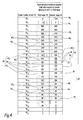
- twenty seven slots 18 are represented, namely slots with order numbers 18 1 to 18 27 , with 18 1 corresponding to the first slot.
- So slots 18 i is also called "slot number i" with i the index of the order number of the slot.
- a rotating electrical machine having 4.5 slots per pole and per phase can be obtained, for example, with the configuration of fifty four slots with four poles or twenty seven slots with two poles.
- the windings arrangements presented on figure 6 in slots numbers 18 1 to 18 27 can be repeated on slots 18 28 to 18 54 in the same order to obtain the winding with fifty four slots.
- Phase winding 22 forms two different types of phase belts 32, 34, namely 5-coil turn phase belt 32 and 4-coil turn phase belt 34, which are alternatively arranged in a circumferential direction of stator 12.
- Each phase belt 32, 34 comprises coil turns 36, and each coil turn 36 includes two connecting bars 42, 44.
- a first connecting bar 42 belongs to a first layer 28 and a second connecting bar 44 belongs to a second layer 30.
- First connecting bar 42 and second connecting bar 44 are separated for each coil turn 36 by a predetermined pitch P, corresponding to a number of slots 18. On the example shown on Figure 5 , the pitch is set to eleven slots.
- each coil turn 36 of the first winding 22 includes a first connecting bar 42 and a second connecting bar 44 for which the angular shift is equal to 0° or 180°.
- coils turns 36 of second 24 and third 26 phase windings with angular shift of respectively 60° or 240°, for the second phase winding 24, and of 120° or 300°, for the third phase winding 26.
- each phase winding 22, 24, 26 could be switched on figure 8.
- the position of phase winding 24 and phase winding 26 could be switched.
- phase winding 26 all first connecting bars 42 of one phase belt 32 are disposed in adjacent slots 18, namely slots number 18 3 to 18 7 .
- all second connecting bars 44 of phase belt 32 are disposed in adjacent slots 18 14 to 18 18 .
- first 42 and second 44 connecting bars of phase belt 34 are respectively disposed in adjacent slots 18 17 to 18 20 and 18 1 to 18 4 .
- a similar arrangement is used for phase windings 22 and 24.
- Phase belts 32, 34 are disposed in slots 18 with a double alternation. More precisely, phase belts 32, 34 of phase windings 22, 24, 26 alternate with an alternation of 5-coil turn phase belt 32 and 4-coil turn phase belt 34.
- an electromagnetic excitation force F acting on a stator core is expressed as follows: F ⁇ ⁇ t ⁇ B 1 2 2 ⁇ cos 2. ⁇ p . ⁇ - 2. ⁇ ⁇ . t + B 1 . B 2 . cos p . ⁇ + 2. ⁇ ⁇ . t + B 1 . B 5 . cos 4. ⁇ p . ⁇ + 2. ⁇ ⁇ . t + B 1 . B 4 . cos 5. ⁇ p . ⁇ - 2. ⁇ ⁇ . t + ...
- a 2.p component appears as a lowest order electromagnetic excitation force and corresponds to the term: B 1 .B 2 .cos(p. ⁇ +2. ⁇ .t).
- 2.p component corresponds to a 2.p node excitation vibration mode, which has a negative influence on the functioning of the machine. Indeed, for a 4-pole machine the 2.p node excitation mode corresponds to a 4-node excitation vibration mode and, for a 2-pole, machine it corresponds to a 2-node excitation vibration mode. These two excitation vibration modes create excessive stator core vibrations.
- the electromagnetic force F includes more harmonics than with an integer number of slots per pole and phase, but they have often lower amplitudes.
- the aim of this invention is to provide a stator winding of a rotating electrical machine where the number of slots per pole and phase is fractional, the reduction of an electromagnetic excitation force of a 2.p component is optimized, the stator and rotor losses are limited, vibrations of the stator are highly decreased and the reliability of the machine is increased.
- the invention concerns a 4.5 slots per pole and phase stator winding of a rotating electrical machine, comprising a rotor and a stator with slots distributed around a rotation axis of the rotor, the stator winding comprising three phase windings and being formed, in each slot, of a first layer and a second layer each phase winding forming at least two phase belts, each phase belt comprising several coils turns connected in series and defining a central axis of the phase belt, each coil turn comprising two connecting bars, with a first connecting bar belonging to the first layer and a second connecting bar belonging to the second layer, whereas:
- the disposition of the phase windings explained above allows optimizing the reduction of the 2.p node excitation mode, with p the number of poles pairs.
- Working conditions and the reliability of a rotating electrical machine comprising such a stator winding are optimized.
- such a 4.5 slots per pole and phase stator winding may incorporate one or several of the following features:
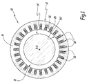
- Figure 1 partially represents a rotating electrical machine 10.
- the electrical machine 10 includes a stator 12 and a rotor 14 disposed coaxially with respect to an axis X-X of rotation of the rotor 14.
- the stator 12 surrounds the rotor 14 and an annular gap 15 is formed between the rotor 14 and the stator 12.
- the stator 12 includes an armature core 16. Some slots 18 are regularly disposed along an internal face 162 of armature core 16, around axis X-X. Slots 18 are intended to receive a stator winding 20 which conveys three phases.
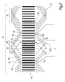
- the stator winding 20 includes three different phase windings, 22, 24, 26, represented on figure 3 and corresponding to a first 22, a second 24 and a third 26 phase windings conveying the three different phases.
- first phase winding 22 is represented with vertical hatchings
- second phase winding 24 is represented with diagonal hatchings inclined of 45° on the left compared to the vertical hatchings
- third phase winding 26 is represented with diagonal hatchings inclined of 45° on the right compared to the vertical hatchings.
- Stator winding 20 is also divided in a first layer 28 and a second layer 30, which go through all slots 18.
- phase belts 32, 34 Each first 22, second 24 and third 26 winding forms phase belts 32, 34, and each phase belt 32, 34 includes several coil turns 36 connected in series, which define a central axis Y of the phase belt. More precisely, there are two different types of phase belts 32, 34, 5-coil turn phase belt 32 and 4-coil turn phase belt 34.
- phase windings 24 and 26 are omitted on figure 2 .
- figure 2 shows phase winding 22 only.
- the central axis Y of a phase belt is an axis parallel to slots 18 and median between the two connecting bars of this phase belt separated by the largest distance measured perpendicularly to slots 18.
- the first layer 28 corresponds to a portion of the stator winding 20 placed in the bottom of the slots 18 and the second layer 30 to another portion of the stator winding 20 placed in the top of slots 18, next to face 162.
- first layer 28 corresponds to a portion of stator winding 12 placed in the top of slots 18 and second layer 30 to another portion of stator winding 12 placed in the bottom of slots 18.
- Each coil turn 36 includes two connecting bars 42, 44, a first connecting bar 42 belonging to first layer 28 and a second connecting bar 44 belonging to second layer 30.
- the ends of the first 42 and second 44 connecting bars are connected in series in order to form coil turn 36.
- First 42 and second 44 connecting bars of one coil turn 36 are separated from each other by a predetermined coil pitch P, corresponding to a number of slots 18.
- the first connecting bars 42 of each phase belt 32, 34 form a group of first connecting bars comprising an outermost first connecting bar 42 O which is further from the central axis Y of this phase belt 32, 34 than the other first connecting bars 42 of the same group and an innermost first connecting bar 42 1 which is closer to the central axis than the other first connecting bars 42 of the same group.
- the first connecting bars in slots 18 12 , 18 13 , 18 14 , 18 15 , 18 16 form a group 46 of first connecting bars of a 5-coil turn phase belt 32.
- the outermost first connecting bar 42 O of this group 46 is in slot 18 12 and the innermost first connecting bar 42 I is in slot 18 16 .
- the second connecting bars 44 of each phase belt 32, 34 form a group of second connecting bars comprising an outermost second connecting bar 44 O , which is further from the central axis Y of this phase belt 32, 34 than the other second connecting bars 44 of the same group and an innermost second connecting bar 44 I which is closer to the central axis Y than the other second connecting bars 44 of the same group.
- the second connecting bars 44 in slots 18 23 , 18 24 , 18 25 , 18 26 , 18 27 form a phase group 47 of second connecting bars of a 5-coil turn phase belt 32.
- the outermost second connecting bar 44 O is in slot 18 27 and the innermost first connecting bar 44 I is in slot 18 23 .
- each 5-coil turn phase belt 32 of the first phase winding 22 has all its first connecting bars 42 disposed in adjacent slots 18 12 to 18 16 and all its second connecting bars 44 disposed in adjacent slots 18 23 to 18 27 .
- the outermost first connecting bars 42 0 are respectively disposed in the slots 18 20 , 18 2 which are respectively separated from the slots 18 22 to 18 25 and 18 4 to 18 7 , which accommodate four other first connecting bars 42 of the same group, by one slot, respectively 18 2 ,18 3 , which accommodates an innermost first connecting bar 42 I of another group of first connecting bars of the 4-coil turn phase belt 34 of, respectively, the third 26 and the second 22 phase windings.
- the outermost second connecting bars 44 0 are respectively disposed in the slots 18 10, 18 19 which are respectively separated from the slots 18 5 to 18 8 and 18 14 to 18 17 , which accommodate four other second connecting bars 44 of the same group, by one slot, respectively 18 9 , 18 18 , which accommodates respectively the innermost second connecting bar 44 I of another group of second connecting bars 34 of the 4-coil turn phase belt of, respectively, the first 22 and the second 24 phase windings.
- specific clips 48 are used to connect the innermost first 42 I connecting bar, on one hand, to the outermost second 44 O connecting bar, on the other hand, to another second connecting bar 44.
- Specific clips 48 are also used to connect the innermost second connecting bar 44 I , on one hand, to the outermost first connecting bar 42 O , on the other hand, to another first connecting bar 42.
- each outermost or innermost, first or second connecting bars 42 I , 42 O , 44 I , 44 O which is separated from some slots which accommodate at least two respectively first 42 or second 44 connecting bars of the same group, by one slot which accommodates respectively a connected first 42 or second 44 connecting bar of another group, is connected to the corresponding second or first connecting bars using a specific clip 48, in order to have coil turns 36 connected in series for each phase belt 32, 34.
- the connection between the phase belt of the first phase winding 22 are not represented but can be realised in different manners.
- the 5-coil turn phase belt 32 and the 4-coil turn phase belt 34 are connected in series.
- the global coil pitch P between the first connecting bars 42 and the second connecting bar 44 is globally set to eleven. More precisely, the global coil pitch P is set to eleven slots for each coil turn 36 comprising a first connecting bar 42 and a second connecting bar 44 of the first phase winding 22 located in a respective slot adjacent with respectively at least one slot comprising a first connecting bar 42 and a second connecting bar 44 of the first phase winding 22. The same applies for each coil turn 36 comprising a first connecting bar 42 and a second connecting bar 44 of the second 24 and third 26 phase windings.
- the global pitch P is fixed to eleven slots in order to reduce the lowest order electromagnetic excitation force corresponding to the term: B 1 .B 2 .cos(p. ⁇ +2. ⁇ .t), as explained in relation to equation 3.
- the global coil pitch P defined as above between the first connecting bars 42 and the second connecting bar 44 of each coil turn 36, is globally set to twelve.
- the 4-coil turn phase belt 34 of the first phase winding 22 has all its first connecting bars 42 disposed in adjacent slots 18 26 , 18 27 , 18 1, 18 2 , and all its second connecting bars 44 disposed in adjacent slot 18 11 to 18 14 .
- the stator 12 could include, on its internal face, fifty-four slots, which implies that the stator 12 would comprise four poles.
- one 5-coil turn phase belt and one 4-coil turn phase belt of a same phase are connected in series and two sets of circuit including series-connected 5-coil turn phase belt and 4-coil turn phase belt are generally connected in parallel and form a phase winding.
- the arrangement of the connecting bars correspond respectively to the one presented on figure 3 and on figure 4 repeated twice.
- the invention concerns all stator windings 20 with 4.5 slots 18 per pole and phase.
- a coil turn 36 which includes a first connecting bar 42 or a second connecting bar 44 of one phase winding in a respective slot which is adjacent to two slots comprising two first connecting bars of respectively two second connecting bars 44 of a different phase winding 22, 24, 26 has generally a coil pitch P different compared to the desired global coil pitch.
- the coil turns arrangement is no more symmetrical because the arrangements of connecting bars 42, 44 is different according to the phase windings 22, 24, 26. These asymmetrical arrangements could create a slight unbalance of the unloaded machine voltage and also a slight unbalance of the phase current when the machine is loaded. The estimated unbalances are low. Therefore the functioning of an electrical machine comprising the stator winding 20 according to the first, second, third and fourth embodiments is optimized and vibrations are reduced.
- the invention allows to optimize the reduction of the 2.p node excitation mode, with p the number of poles pairs. Therefore the stator losses are limited, the vibrations of the stator are highly decreased, and the reliability of the electrical machine comprising stator winding 20 is increased.
- first layer 28 corresponds to a portion of stator winding 12 placed in the top of slots 18 and second layer 30 to another portion of stator winding 12 placed in the bottom of slots 18.
- each phase winding 22, 24, 26 in the different slots 18 could be switched.
- the position of phase winding 24 and phase winding 26 could be switched.
Landscapes
- Engineering & Computer Science (AREA)
- Power Engineering (AREA)
- Windings For Motors And Generators (AREA)
Priority Applications (4)
| Application Number | Priority Date | Filing Date | Title |
|---|---|---|---|
| EP20130193415 EP2843807A2 (fr) | 2013-09-03 | 2013-11-19 | Enroulements statoriques d'une machine électrique tournante |
| EP14757897.5A EP3042437A2 (fr) | 2013-09-03 | 2014-08-22 | Enroulement de stator d'une machine électrique rotative |
| PCT/EP2014/067892 WO2015032633A2 (fr) | 2013-09-03 | 2014-08-22 | Enroulement de stator d'une machine électrique rotative |
| ZA2016/01776A ZA201601776B (en) | 2013-09-03 | 2016-03-15 | Stator winding of a rotating electrical machine |
Applications Claiming Priority (2)
| Application Number | Priority Date | Filing Date | Title |
|---|---|---|---|
| EP13182831.1A EP2843806B1 (fr) | 2013-09-03 | 2013-09-03 | Enroulement de stator d'une machine électrique tournante |
| EP20130193415 EP2843807A2 (fr) | 2013-09-03 | 2013-11-19 | Enroulements statoriques d'une machine électrique tournante |
Publications (1)
| Publication Number | Publication Date |
|---|---|
| EP2843807A2 true EP2843807A2 (fr) | 2015-03-04 |
Family
ID=49083590
Family Applications (3)
| Application Number | Title | Priority Date | Filing Date |
|---|---|---|---|
| EP13182831.1A Not-in-force EP2843806B1 (fr) | 2013-09-03 | 2013-09-03 | Enroulement de stator d'une machine électrique tournante |
| EP20130193415 Withdrawn EP2843807A2 (fr) | 2013-09-03 | 2013-11-19 | Enroulements statoriques d'une machine électrique tournante |
| EP14757897.5A Withdrawn EP3042437A2 (fr) | 2013-09-03 | 2014-08-22 | Enroulement de stator d'une machine électrique rotative |
Family Applications Before (1)
| Application Number | Title | Priority Date | Filing Date |
|---|---|---|---|
| EP13182831.1A Not-in-force EP2843806B1 (fr) | 2013-09-03 | 2013-09-03 | Enroulement de stator d'une machine électrique tournante |
Family Applications After (1)
| Application Number | Title | Priority Date | Filing Date |
|---|---|---|---|
| EP14757897.5A Withdrawn EP3042437A2 (fr) | 2013-09-03 | 2014-08-22 | Enroulement de stator d'une machine électrique rotative |
Country Status (3)
| Country | Link |
|---|---|
| EP (3) | EP2843806B1 (fr) |
| WO (2) | WO2015032624A1 (fr) |
| ZA (1) | ZA201601776B (fr) |
Citations (1)
| Publication number | Priority date | Publication date | Assignee | Title |
|---|---|---|---|---|
| EP2503673A2 (fr) | 2011-03-24 | 2012-09-26 | Kabushiki Kaisha Toshiba | Enroulement d'armature de machine électrique rotative |
Family Cites Families (5)
| Publication number | Priority date | Publication date | Assignee | Title |
|---|---|---|---|---|
| SU1053222A1 (ru) * | 1982-03-29 | 1983-11-07 | Научно-Исследовательский Проектно-Конструкторский И Технологический Институт Тяжелого Электромашиностроения Харьковского Завода "Электротяжмаш" Им.В.И.Ленина | Несимметрична петлева обмотка с дробным числом пазов на полюс и фазу |
| RU2298869C2 (ru) * | 2004-08-09 | 2007-05-10 | Открытое акционерное общество Ярославский электромашиностроительный завод - ОАО "ELDIN" (ЭЛДИН) | ТРЕХФАЗНАЯ НЕСИММЕТРИЧНАЯ ДРОБНАЯ ОБМОТКА ПРИ 2p=6c ПОЛЮСАХ В z=42c ПАЗАХ |
| RU2324277C2 (ru) * | 2004-11-15 | 2008-05-10 | Открытое акционерное общество Ярославский электромашиностроительный завод-ОАО "ELDIN" (ЭЛДИН) | ТРЕХФАЗНАЯ ДВУХСЛОЙНАЯ ЭЛЕКТРОМАШИННАЯ ОБМОТКА В z=132·c ПАЗАХ ПРИ 2p=26·c ПОЛЮСАХ (q=44/13) |
| RU2324276C2 (ru) * | 2004-11-15 | 2008-05-10 | Открытое акционерное общество Ярославский электромашиностроительный завод-ОАО "ELDIN" (ЭЛДИН) | ТРЕХФАЗНАЯ НЕСИММЕТРИЧНАЯ ДРОБНАЯ ОБМОТКА ПРИ 2p=12·c ПОЛЮСАХ В z=75·c ПАЗАХ |
| RU2324273C2 (ru) * | 2004-12-02 | 2008-05-10 | Открытое акционерное общество Ярославский электромашиностроительный завод-ОАО "ELDIN" (ЭЛДИН) | ТРЕХФАЗНАЯ ДВУХСЛОЙНАЯ ЭЛЕКТРОМАШИННАЯ ОБМОТКА В z=102·c ПАЗАХ ПРИ 2p=26·c ПОЛЮСАХ (q=34/13) |
-
2013
- 2013-09-03 EP EP13182831.1A patent/EP2843806B1/fr not_active Not-in-force
- 2013-11-19 EP EP20130193415 patent/EP2843807A2/fr not_active Withdrawn
-
2014
- 2014-08-20 WO PCT/EP2014/067771 patent/WO2015032624A1/fr not_active Ceased
- 2014-08-22 EP EP14757897.5A patent/EP3042437A2/fr not_active Withdrawn
- 2014-08-22 WO PCT/EP2014/067892 patent/WO2015032633A2/fr not_active Ceased
-
2016
- 2016-03-15 ZA ZA2016/01776A patent/ZA201601776B/en unknown
Patent Citations (1)
| Publication number | Priority date | Publication date | Assignee | Title |
|---|---|---|---|---|
| EP2503673A2 (fr) | 2011-03-24 | 2012-09-26 | Kabushiki Kaisha Toshiba | Enroulement d'armature de machine électrique rotative |
Also Published As
| Publication number | Publication date |
|---|---|
| ZA201601776B (en) | 2018-05-30 |
| EP2843806B1 (fr) | 2016-02-24 |
| EP3042437A2 (fr) | 2016-07-13 |
| EP2843806A1 (fr) | 2015-03-04 |
| WO2015032624A1 (fr) | 2015-03-12 |
| WO2015032633A3 (fr) | 2015-08-20 |
| WO2015032633A2 (fr) | 2015-03-12 |
Similar Documents
| Publication | Publication Date | Title |
|---|---|---|
| US6628031B2 (en) | Harmonic-frequency synchronous machine with flux concentration | |
| US8461739B2 (en) | Stator for an electric machine | |
| US7732967B2 (en) | Electrical machine comprising a winding system with coil groups | |
| US10461617B2 (en) | Mirroring of high rotor pole switched reluctance machines | |
| JP6288369B2 (ja) | 回転電機 | |
| EP2503673B1 (fr) | Enroulement d'armature de machine électrique rotative | |
| KR20150086381A (ko) | 회전 전기 | |
| AU2014377432A1 (en) | Synchronous generator in a gearless wind turbine | |
| KR20130080778A (ko) | 인터폴라 구조를 갖는 회전 전기 기계 회전자 | |
| JP2005510991A (ja) | 環状巻線を有する電気同期機 | |
| US20130221792A1 (en) | Armature winding of rotating electrical machine | |
| US10848021B2 (en) | Switched reluctance machine with short flux path | |
| US10468929B2 (en) | Rotor for a rotating electrical machine | |
| CN107546889A (zh) | 包括转子和定子的电机 | |
| EP2843807A2 (fr) | Enroulements statoriques d'une machine électrique tournante | |
| US11791683B2 (en) | Multi-tooth coil winding for a three-phase rotating field machine | |
| JPH08256461A (ja) | 永久磁石形モータ | |
| JP2016077098A (ja) | 回転電機 | |
| US7095152B2 (en) | Stator for a line-start electric motor | |
| US20160329758A1 (en) | Magnetically isolated electrical machines | |
| US20200412218A1 (en) | Rotor | |
| US20010045787A1 (en) | Permanent magnet synchronous motor | |
| RU2516246C2 (ru) | Статор вращающейся электрической машины с постоянным возбуждением | |
| SU1453538A1 (ru) | Синхронна двухчастотна машина с соотношением частот 1:2 | |
| JPH05300714A (ja) | 交流電機 |
Legal Events
| Date | Code | Title | Description |
|---|---|---|---|
| 17P | Request for examination filed |
Effective date: 20131119 |
|
| AK | Designated contracting states |
Kind code of ref document: A2 Designated state(s): AL AT BE BG CH CY CZ DE DK EE ES FI FR GB GR HR HU IE IS IT LI LT LU LV MC MK MT NL NO PL PT RO RS SE SI SK SM TR |
|
| AX | Request for extension of the european patent |
Extension state: BA ME |
|
| PUAI | Public reference made under article 153(3) epc to a published international application that has entered the european phase |
Free format text: ORIGINAL CODE: 0009012 |
|
| STAA | Information on the status of an ep patent application or granted ep patent |
Free format text: STATUS: THE APPLICATION HAS BEEN WITHDRAWN |
|
| 18W | Application withdrawn |
Effective date: 20160222 |