EP2844169B1 - Système à plaque osseuse pour l'ostéosynthèse - Google Patents
Système à plaque osseuse pour l'ostéosynthèse Download PDFInfo
- Publication number
- EP2844169B1 EP2844169B1 EP13719713.3A EP13719713A EP2844169B1 EP 2844169 B1 EP2844169 B1 EP 2844169B1 EP 13719713 A EP13719713 A EP 13719713A EP 2844169 B1 EP2844169 B1 EP 2844169B1
- Authority
- EP
- European Patent Office
- Prior art keywords
- screw
- hole
- bone
- bone plate
- head
- Prior art date
- Legal status (The legal status is an assumption and is not a legal conclusion. Google has not performed a legal analysis and makes no representation as to the accuracy of the status listed.)
- Not-in-force
Links
- 210000000988 bone and bone Anatomy 0.000 title claims description 152
- 230000007704 transition Effects 0.000 description 7
- 239000012634 fragment Substances 0.000 description 4
- 208000010392 Bone Fractures Diseases 0.000 description 2
- 230000006378 damage Effects 0.000 description 2
- 238000005516 engineering process Methods 0.000 description 2
- 230000013011 mating Effects 0.000 description 2
- 238000000034 method Methods 0.000 description 2
- 238000010079 rubber tapping Methods 0.000 description 2
- 208000008924 Femoral Fractures Diseases 0.000 description 1
- 206010017076 Fracture Diseases 0.000 description 1
- 208000001164 Osteoporotic Fractures Diseases 0.000 description 1
- 230000006978 adaptation Effects 0.000 description 1
- 238000004873 anchoring Methods 0.000 description 1
- 230000015572 biosynthetic process Effects 0.000 description 1
- 230000000295 complement effect Effects 0.000 description 1
- 230000006835 compression Effects 0.000 description 1
- 238000007906 compression Methods 0.000 description 1
- 230000001419 dependent effect Effects 0.000 description 1
- 230000000694 effects Effects 0.000 description 1
- 230000003203 everyday effect Effects 0.000 description 1
- 239000007943 implant Substances 0.000 description 1
- 230000003993 interaction Effects 0.000 description 1
- 230000001009 osteoporotic effect Effects 0.000 description 1
Images


Classifications
-
- A—HUMAN NECESSITIES
- A61—MEDICAL OR VETERINARY SCIENCE; HYGIENE
- A61B—DIAGNOSIS; SURGERY; IDENTIFICATION
- A61B17/00—Surgical instruments, devices or methods
- A61B17/56—Surgical instruments or methods for treatment of bones or joints; Devices specially adapted therefor
- A61B17/58—Surgical instruments or methods for treatment of bones or joints; Devices specially adapted therefor for osteosynthesis, e.g. bone plates, screws or setting implements
- A61B17/68—Internal fixation devices, including fasteners and spinal fixators, even if a part thereof projects from the skin
- A61B17/80—Cortical plates, i.e. bone plates; Instruments for holding or positioning cortical plates, or for compressing bones attached to cortical plates
- A61B17/8052—Cortical plates, i.e. bone plates; Instruments for holding or positioning cortical plates, or for compressing bones attached to cortical plates immobilised relative to screws by interlocking form of the heads and plate holes, e.g. conical or threaded
- A61B17/8057—Cortical plates, i.e. bone plates; Instruments for holding or positioning cortical plates, or for compressing bones attached to cortical plates immobilised relative to screws by interlocking form of the heads and plate holes, e.g. conical or threaded the interlocking form comprising a thread
-
- A—HUMAN NECESSITIES
- A61—MEDICAL OR VETERINARY SCIENCE; HYGIENE
- A61B—DIAGNOSIS; SURGERY; IDENTIFICATION
- A61B17/00—Surgical instruments, devices or methods
- A61B17/56—Surgical instruments or methods for treatment of bones or joints; Devices specially adapted therefor
- A61B17/58—Surgical instruments or methods for treatment of bones or joints; Devices specially adapted therefor for osteosynthesis, e.g. bone plates, screws or setting implements
- A61B17/68—Internal fixation devices, including fasteners and spinal fixators, even if a part thereof projects from the skin
- A61B17/80—Cortical plates, i.e. bone plates; Instruments for holding or positioning cortical plates, or for compressing bones attached to cortical plates
- A61B17/8033—Cortical plates, i.e. bone plates; Instruments for holding or positioning cortical plates, or for compressing bones attached to cortical plates having indirect contact with screw heads, or having contact with screw heads maintained with the aid of additional components, e.g. nuts, wedges or head covers
-
- A—HUMAN NECESSITIES
- A61—MEDICAL OR VETERINARY SCIENCE; HYGIENE
- A61B—DIAGNOSIS; SURGERY; IDENTIFICATION
- A61B17/00—Surgical instruments, devices or methods
- A61B17/56—Surgical instruments or methods for treatment of bones or joints; Devices specially adapted therefor
- A61B17/58—Surgical instruments or methods for treatment of bones or joints; Devices specially adapted therefor for osteosynthesis, e.g. bone plates, screws or setting implements
- A61B17/68—Internal fixation devices, including fasteners and spinal fixators, even if a part thereof projects from the skin
- A61B17/80—Cortical plates, i.e. bone plates; Instruments for holding or positioning cortical plates, or for compressing bones attached to cortical plates
- A61B17/8052—Cortical plates, i.e. bone plates; Instruments for holding or positioning cortical plates, or for compressing bones attached to cortical plates immobilised relative to screws by interlocking form of the heads and plate holes, e.g. conical or threaded
-
- A—HUMAN NECESSITIES
- A61—MEDICAL OR VETERINARY SCIENCE; HYGIENE
- A61B—DIAGNOSIS; SURGERY; IDENTIFICATION
- A61B17/00—Surgical instruments, devices or methods
- A61B17/56—Surgical instruments or methods for treatment of bones or joints; Devices specially adapted therefor
- A61B17/58—Surgical instruments or methods for treatment of bones or joints; Devices specially adapted therefor for osteosynthesis, e.g. bone plates, screws or setting implements
- A61B17/68—Internal fixation devices, including fasteners and spinal fixators, even if a part thereof projects from the skin
- A61B17/84—Fasteners therefor or fasteners being internal fixation devices
- A61B17/86—Pins or screws or threaded wires; nuts therefor
- A61B17/8605—Heads, i.e. proximal ends projecting from bone
Definitions
- the invention relates to technologies in the field of bone plate systems for osteosynthesis.
- Bone plate systems serve the angular stable fixation of a bone plate by means of associated screws for osteosynthesis on the human or animal body.
- Numerous bone plate systems are known which typically include a bone plate having an array of multiple through holes and associated screws.
- fixing screws may be provided, which in turn are not screwed into the bone, but rather in a thread formed in the bone plate.
- Such fastening screws then serve, for example, for fixing the bone screws (cf., for example, the documents EP 1 702 577 A2 . WO 2006/014436 A1 such as AT 406 446 B ).
- a fixing screw is used to fix several bone screws.
- WO 2005/041 796 A1 discloses a bone plate provided with oblong holes.
- Angularly stable plate-screw connections to osteosynthesis plates have the advantage of better anchoring of the bone plate to the bone. This is particularly advantageous for joint-near bone fractures, since in this way joint-near bone fragments can be better grasped and fixed.
- the advantage of angle-stable plate-screw connections is gaining in significance in osteoporotic fractures close to the joints, since bone screws without angular stability are less able to fix osteoporotic bone.
- Angular stable plate-screw connections can be divided into monoaxial and polyaxial plate-screw connections.
- Examples of monoaxial angularly stable plate-screw connections are in the documents DE 10 2005 004 841 B4 or DE 10 2005 043 285 B3 executed. These systems are characterized by having male threaded heads which engage in corresponding internal threads of plates. If a screw is screwed in during an operation, the positive connection between the external thread of the screw head and the internal thread of the bone plate causes an angle-stable plate-screw connection during the last turns of the screwing process.
- bone plate systems have been proposed in which bone screws are variable in terms of their pivotal or angular position with respect to the bone plate in use.
- a bone plate system is for example in the document DE 10 2006 000 948 A1 described.
- WO 2007/025520 A1 is a bone plate with at least one screw for angular stable fixation disclosed.
- Another example of a polyaxial angular stable plate-and-bolt connection is in DE 10 2005 042 766 B4 disclosed.
- the described therein formation of an internal thread of six internal threaded posts succeeds to screw ball screws with a special external thread in the polyaxial direction and to fix during the last turns of the screwing angle stable. Due to the clinical advantages of a polyaxial angle stable fixation option, such plate screw systems have become increasingly popular in everyday clinical practice.
- a device for angular stable fixation and compression of a fracture site on a bone is known.
- the known bone plate has several individual holes, in each of which a bone screw can be screwed. In connection with the individual holes can be provided that they have a sickle-like hole extension.
- the document WO 2009/058969 A1 also relates to a bone plate system in which the bone plate has a plurality of individual holes for receiving exactly one screw.
- the bone plate has a plurality of individual holes for receiving exactly one screw.
- pillars are provided with projections which in the screwed state of the respective screw with a thread on the screw head in Engage.
- the plurality of columns with projections are separated in the respective hole from each other by areas which are free of such projections and thus have a smooth surface.
- a bone plate system for osteosynthesis in which for fixing the bone plate on the bone in a pivot hole and a clamping screw in a clamping hole a clamping screw are screwed, such that in the screwed state, the pivoting screw and the clamping screw are fixed multi-dimensionally stable angle by the screw heads the pivoting screw and the clamping screw are secured against each other and with the bone plate against a relative movement, wherein the pivoting screw and the clamping screw are each designed as a bone screw.
- the object of the invention is to provide improved technologies for bone plate systems for osteosynthesis, with which the multi-dimensional angular stability of the introduced into the bone plate screws is optimized.
- a bulge is provided, which expands the through hole and is arranged opposite the opening.
- the bone screw and the further bone screw are fixed in a multi-dimensionally angularly stable manner by the screw heads of the bone screw and the further bone screw being secured against relative movement with one another and with the bone plate by means of a tensioned multipoint bearing.
- the tensioned multipoint bearing is formed in the through hole with attachments of the bone screw at transition areas between the bulge and the respective adjacent to the bulge through-hole portion.
- the transition regions are preferably formed as corner regions in which the bone screw comes into abutment in the screwed-in state. The bone screw is thereby clamped in the through hole at the two opposite transition areas.
- the radial projections and / or grooves are formed continuously from the edge of the bulge to the edge of the opening between the through hole and the further through hole, preferably in both halves of the through hole.
- the surface structure on the screw head can be positively engaged with the radial projections and / or grooves in the screwed-in state of the bone screw.
- the bulge is formed with a sickle shape.
- the outer shape of the bulge may correspond in one embodiment to a circular arc portion, wherein the associated radius of the circular arc portion is smaller than the radius of the through hole.
- the radius of the circular arc portion of the bulge is at most about 2/3 of the radius of the through hole. It is further preferred that the radius of the circular arc portion of the bulge corresponds to at most about 1/2 of the radius of the through hole.
- the bulge has a smooth surface.
- the bulge is free of radial projections and radial grooves. Also, no thread is provided in the bulge here.
- a straight-line distance between opposite ends of the bulge is smaller than the diameter of the through hole.
- the rectilinear distance is at most 2/3 of the diameter of the through-hole. It is further preferred that the straight-line distance between the opposite ends of the bulge is at most about half of the diameter of the through-hole.
- the through hole with a ball head receptacle opening toward the top of the bone plate and the screw head of the bone screw are formed as an associated ball head, which is at least partially arranged in the ball head receptacle of the through hole in the screwed-in state of the bone screw.
- the screw head of the bone screw insofar as it is received in the ball seat, can be arranged in a form-fitting manner therein.
- the further through hole may be formed with a ball head receptacle which opens toward the top of the bone plate, into which the screw head of the bone screw, which is formed as an associated ball head, engages in the screwed-in state.
- both the bone screw and the further bone screw are formed with a ball head, which is arranged in the screwed state each in a ball head socket.
- the ball head is provided with a first and a second thread, which are formed superimposed on the ball head.
- the first and the second thread may be, for example, a right-hand and a left-hand thread.
- a further thread and / or horizontal circumferential grooves may be provided on the ball head.
- clamping hole and pivot hole generally relate to a through hole and another through hole.
- a training provides that the bone plate is formed with an extension region adjacent to the clamping hole, such that the bone plate at least partially yielding and free of Einschraubtik due to the interaction between the external thread and the internal thread when screwing the clamping screw in the internal thread of the clamping hole plastic deformation is deformable.
- the expansion region providing embodiment is preferably carried out such that the external thread is formed as a conical external thread and the internal thread as a cylindrical internal thread.
- the clamping screw can optionally be completely screwed into the through hole with the screw head.
- the screw head is held on the one hand by the elastic tension in each position against rotation on the one hand, on the other hand, but the bone plate is not irreversibly deformed in their plastic range, d. H. overstretched.
- the clamping screw can be sensitively screwed in just as far as it is necessary to firmly fix the bone plate to the bone and to achieve the clamping with the swivel screw, while ensuring that the screw head in his In the most elevated areas, the bone plate is not projected so that the fixed bone plate as a whole forms - with the clamping screw - a unit which essentially fits snugly against the bone without elevations.
- the adjacent expansion region is at least partially formed as a web or part of a ring.
- the screw shank has a length which is equal to or shorter than the length of the screw shank of the swivel screw.
- the length of the shank of the clamping screw is at most half, preferably at most one third of the length of the shank of the swivel screw.
- the length of the shank of the clamping screw shortened in relation to the screw shank of the swivel screw supports, in particular, the versatility of the swivel or angular positions of the swivel screw with respect to the bone plate.
- the shaft of the pivoting screw can also be pivoted in an area below the lower shaft end of the clamping screw.
- a training provides that in the bone plate at least one further the pivot hole or the clamping hole executed and corresponding to the pivot hole and the clamping hole through hole is formed, that in the further through hole another bone screw is inserted, which performed the pivoting screw or the clamping screw accordingly is, and that the screw head of the other bone screw in the screwed state with the screw heads, such as the ball head and the screw head with conical external thread, and the bone plate is clamped.
- an arrangement of at least three mutually associated through holes is formed, in which a respective bone screw is screwed. It can be provided any combination of swivel screws and clamping screws, optionally threaded portions of the screw heads of the involved bone screws mesh positively in pairs and thus support each other and are jointly secured to the bone plate against relative movement.
- the pivot hole and the associated clamping hole may be part of a so-called plate hole group with further through holes or these form.
- the bone plate may have multiple plate hole groups. Additional through holes can be formed as round or oblong holes for accurate recording of round, countersunk, spherical, lens, bulb or cone head screws.
- a particularly advantageous for the bone plate swivel screw has a spherical screw head, which is flattened at the head (north).
- a preferred clamping screw is designed as a countersunk screw with a cylindrical thread below the countersunk head.
- the shape of the lower surface of the countersunk screw can be rounded in this case to improve the contact surface and be designed to match the spherical shape of the Schwenkschraubenkopfes.
- the length of the cylindrical thread of the bolt is a multiple of the plate thickness, for example, 0.9 times. hereby
- the cylindrical thread of the clamping screw can first securely grasp in the cylindrical mating thread of the plate and press the pivoting screw in its planned course in the further course of screwing, so that the greatest possible clamping effect is provided. This is particularly advantageous for slightly tilted swivel screws.
- the cylinder thread of the clamping screw slightly projects beyond the lower surface of the bone plate, and therefore the beginning of the screw tip-side cylinder thread can be designed as a self-tapping thread, so that the cylinder thread can penetrate slightly into the bone to be screwed.
- the further, usually longer, screw-tip portion of the bolt of the clamping screw is typically designed like a bone screw with a self-tapping thread.
- the external thread of the clamping screw which is to take in the mating thread of the bone plate may be formed as a cone thread, wherein the inclination angle of the cone to the longitudinal axis of the screw fails less than the inclination angle of the countersunk head.
- the swivel screw can be first poly-axially screwed in the application, which makes it possible to fix bone fragments and to pull on the plate. Subsequently, the clamping screw can be screwed in and fix at the same time self-locking and the pivoting screw during the last turns angle stable.
- the clamping screw itself acts as a monoaxial angle stable screw.
- the thread may advantageously have rounded tips.
- the surface of the swivel screw is designed such that the round head surface of the swivel screw perpendicular to the equator of the screw head has longitudinal segments, for example, twelve length segments. Each longitudinal segment is designed with a réellespitzgewindeklade to serve as a positive abutment for the clamping screw.
- the clamping screw has a conical outer point thread, which on the one hand allows positive locking of the plate via a conical inner point thread of the clamping hole.
- the swivel screw is fixed in a form-fitting manner via its female threaded posts on the screw head.
- the internal thread columns on the pivoting screw for example, formed such that the surface of the screw head portion of the pivot screw still has enough spherical surface, so that no thread destruction or burring occurs during tightening of the pivoting screw.
- the surface of the pivot hole may be equipped with at least one réellespitzgewindeklave to give the mounting a higher angular stability.
- the swivel screw can also be equipped with preferably twelve internally threaded columns, said internal pointed threaded columns can advantageously be formed on the surface of the swivel hole with an adapted or passable thread form.
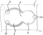
- Fig. 4 shows a schematic representation of a tensioned three-point bearing.
- Circles 20, 21 and 22 symbolize the attachment of the screw head 9 of the bone screw 10 in the corner regions 14, 15 in the through hole 2 on the one hand and an attachment of the screw head 11 of the other bone screw 12 in the further through hole 3 the opening 6 opposite.
- Another triangular tension results between the deposits in the corner areas on the one hand and the contact between the screw heads 9, 11 of the bone screw 10 and the further bone screw 12 (not shown in FIG Fig. 4 ).
Landscapes
- Health & Medical Sciences (AREA)
- Orthopedic Medicine & Surgery (AREA)
- Surgery (AREA)
- Life Sciences & Earth Sciences (AREA)
- Heart & Thoracic Surgery (AREA)
- Nuclear Medicine, Radiotherapy & Molecular Imaging (AREA)
- Engineering & Computer Science (AREA)
- Biomedical Technology (AREA)
- Neurology (AREA)
- Medical Informatics (AREA)
- Molecular Biology (AREA)
- Animal Behavior & Ethology (AREA)
- General Health & Medical Sciences (AREA)
- Public Health (AREA)
- Veterinary Medicine (AREA)
- Surgical Instruments (AREA)
Claims (9)
- Système de plaques à os pour ostéosynthèse, comprenant :- une vis à os (10) dont la tête de vis (9) présente une structure de surface au moins par tronçons,- une vis à os supplémentaire (12) dont la tête de vis (11) présente une structure de surface au moins par tronçons, et- une plaque à os (1), la plaque à os (1) présentantdans lequel dans l'état vissé, la vis à os (10) et la vis à os supplémentaire (12) sont fixées stables en angle de façon pluridimensionnelle,- un trou traversant (2) qui est configuré pour recevoir la vis à os (10) de façon polyaxiale,- un trou traversant supplémentaire (3) attribué au trou traversant (2) qui est configuré pour recevoir la vis à os supplémentaire (12), et- une percée (6) qui relie le trou traversant (2) et le trou traversant supplémentaire (3),
caractérisé en ce que- la plaque à os (1) présente un bombement (7), lequel est formé sur le trou traversant (2) en élargissant celui-ci et face à la percée (6), et- dans la fixation stable en angle de façon pluridimensionnelle, les têtes de vis (9, 11) de la vis à os (10) et de la vis à os supplémentaire (12) sont assurées contre un mouvement relatif entre elles ainsi qu'avec la plaque à os (1) au moyen d'une fixation en plusieurs points serrée, sont formées dans les fixations (20, 21, 22) de la vis à os (10) sur des zones de transition (13, 14) entre le bombement (7) et le tronçon de trou traversant (15, 16) voisin respectivement du bombement (7) dans le trou traversant (2), entre les têtes de vis (9, 11) ainsi que la vis à os supplémentaire (12) dans le trou traversant supplémentaire (3). - Système de plaques à os selon la revendication 1, caractérisé en ce que des saillies et/ou rainures radiales (17) sont formées au moins par tronçons dans le trou traversant (2) en-dehors du bombement (7), avec lesquelles la structure de surface sur la tête de vis (9) est en prise au moins par tronçons lorsque la vis à os (10) est vissée.
- Système de plaques à os selon la revendication 1 ou 2, caractérisé en ce que des saillies et/ou rainures radiales sont formées au moins par tronçons dans le trou traversant supplémentaire (3), avec lesquelles la structure de surface sur la tête de vis (11) est en prise au moins par tronçons lorsque la vis à os supplémentaire (12) est vissée.
- Système de plaques à os selon au moins l'une des revendications précédentes, caractérisé en ce que le bombement (7) a une forme de faucille.
- Système de plaques à os selon au moins l'une des revendications précédentes, caractérisé en ce que le bombement (7) présente une surface lisse.
- Système de plaques à os selon au moins l'une des revendications précédentes, caractérisé en ce qu'une distance droite entre des extrémités opposées du bombement (7) est inférieure au diamètre du trou traversant (2).
- Système de plaques à os selon au moins l'une des revendications précédentes, caractérisé en ce que le bombement (7) est formé essentiellement en symétrie de miroir pour prolonger la ligne reliant les points centraux du trou traversant (2) et du trou traversant supplémentaire (3).
- Système de plaques à os selon au moins l'une des revendications précédentes, caractérisé en ce que le trou traversant (2) est formé avec une réception de tête sphérique (4) ouvrant en direction du haut de la plaque à os (1) et la tête de vis (9) de la vis à os (10) est formée en tant qu'une tête sphérique correspondante qui est disposée au moins partiellement dans la réception de tête sphérique (4) du trou traversant (2) lorsque la vis à os (10) est vissée.
- Système de plaques à os selon la revendication 8, caractérisé en ce que la tête de vis est dotée d'un premier et d'un second filet qui sont formés en se superposant sur la tête sphérique.
Applications Claiming Priority (2)
| Application Number | Priority Date | Filing Date | Title |
|---|---|---|---|
| DE102012103894.5A DE102012103894B4 (de) | 2012-05-03 | 2012-05-03 | Knochenplattensystem für Osteosynthese |
| PCT/DE2013/100117 WO2013163985A1 (fr) | 2012-05-03 | 2013-03-28 | Système à plaque osseuse pour l'ostéosynthèse |
Publications (2)
| Publication Number | Publication Date |
|---|---|
| EP2844169A1 EP2844169A1 (fr) | 2015-03-11 |
| EP2844169B1 true EP2844169B1 (fr) | 2017-09-13 |
Family
ID=48236625
Family Applications (1)
| Application Number | Title | Priority Date | Filing Date |
|---|---|---|---|
| EP13719713.3A Not-in-force EP2844169B1 (fr) | 2012-05-03 | 2013-03-28 | Système à plaque osseuse pour l'ostéosynthèse |
Country Status (5)
| Country | Link |
|---|---|
| US (1) | US9788874B2 (fr) |
| EP (1) | EP2844169B1 (fr) |
| DE (1) | DE102012103894B4 (fr) |
| ES (1) | ES2649901T3 (fr) |
| WO (1) | WO2013163985A1 (fr) |
Families Citing this family (10)
| Publication number | Priority date | Publication date | Assignee | Title |
|---|---|---|---|---|
| US10251757B2 (en) * | 2008-09-17 | 2019-04-09 | Skeletal Dynamics Llc | Grooved slot allowing adjustment of the position of a bone fixation device for osteosynthesis |
| US8728133B2 (en) | 2009-06-30 | 2014-05-20 | The Penn State Research Foundation | Bone repair system and method |
| US20150238233A1 (en) * | 2012-08-09 | 2015-08-27 | Trinity Orthopedics, Llc | Intervertebral Plate Systems and Methods of Use |
| US10231767B2 (en) | 2013-03-15 | 2019-03-19 | The Penn State Research Foundation | Bone repair system, kit and method |
| US11833055B2 (en) | 2016-02-28 | 2023-12-05 | Integrated Shoulder Collaboration, Inc. | Shoulder arthroplasty implant system |
| EP4140423A1 (fr) | 2016-02-28 | 2023-03-01 | Integrated Shoulder Collaboration, Inc. | Système d'implant d'arthroplastie de l'épaule |
| US10687953B2 (en) * | 2017-02-17 | 2020-06-23 | The Board Of Regents Of The University Of Texas System | Apparatuses and methods for anterior cervical transarticular fixation |
| US11039865B2 (en) | 2018-03-02 | 2021-06-22 | Stryker European Operations Limited | Bone plates and associated screws |
| CN108703799A (zh) * | 2018-05-25 | 2018-10-26 | 大博医疗科技股份有限公司 | 加压锁定接骨板装置 |
| CN119970203B (zh) * | 2025-04-17 | 2025-07-15 | 北京贝思达生物技术有限公司 | 锁定金属接骨板 |
Family Cites Families (86)
| Publication number | Priority date | Publication date | Assignee | Title |
|---|---|---|---|---|
| US2662988A (en) | 1948-07-15 | 1953-12-15 | Gen Electric | Base for motors |
| GB1369594A (en) | 1970-09-30 | 1974-10-09 | Cambridge Scientific Instr Ltd | Scientific instruments |
| US3741205A (en) | 1971-06-14 | 1973-06-26 | K Markolf | Bone fixation plate |
| CH645013A5 (de) | 1980-04-14 | 1984-09-14 | Wenk Wilh Ag | Osteosynthetische kompressionsplatte. |
| US4454876A (en) | 1982-05-25 | 1984-06-19 | University Of Pittsburgh | Pelvic fixation plate and method of implanting same |
| US4616634A (en) | 1985-03-07 | 1986-10-14 | Commonwealth Of Puerto Rico | Soft tissue protector for use in oral and maxillofacial surgery |
| GB8529274D0 (en) | 1985-11-28 | 1986-01-02 | Itw Ltd | Threaded fastening systems |
| DE3601715A1 (de) | 1986-01-22 | 1987-07-23 | Heinl Thomas | Chirurgisches instrumentenset zum verbinden von knochenfragmenten |
| GB8609640D0 (en) | 1986-04-19 | 1986-05-21 | Lucas Ind Plc | Disc brakes |
| US4959065A (en) | 1989-07-14 | 1990-09-25 | Techmedica, Inc. | Bone plate with positioning member |
| FR2667913B3 (fr) | 1990-10-16 | 1992-12-31 | Biomecanique Integree | Systeme pour l'assemblage d'au moins deux elements par vis ou analogue. |
| US5529075A (en) | 1994-09-12 | 1996-06-25 | Clark; David | Fixation device and method for repair of pronounced hallux valgus |
| KR100329539B1 (ko) | 1995-03-27 | 2002-11-13 | 신테스 아게 츄어 | 뼈고정판 |
| EP0848600B1 (fr) | 1995-09-06 | 2001-05-09 | SYNTHES AG Chur | Plaque pour liaison osseuse |
| FR2739151B1 (fr) | 1995-09-22 | 1997-11-28 | Numedic | Dispositif de solidarisation d'une piece sur un support |
| AT937U3 (de) | 1996-03-26 | 1996-12-27 | Stoffella Rudolf Dr | Implantat zur fixierung einer osteotomie |
| US6632224B2 (en) | 1996-11-12 | 2003-10-14 | Triage Medical, Inc. | Bone fixation system |
| IL119942A (en) | 1996-12-31 | 2002-03-10 | M P R S Ltd | Modular implant for pelvis reconstruction |
| US6193721B1 (en) | 1997-02-11 | 2001-02-27 | Gary K. Michelson | Multi-lock anterior cervical plating system |
| ZA983955B (en) | 1997-05-15 | 2001-08-13 | Sdgi Holdings Inc | Anterior cervical plating system. |
| AT406446B (de) | 1997-09-09 | 2000-05-25 | Werner Ing Fuchs | Winkelstabile schraubenverbindung |
| US6129728A (en) | 1998-02-18 | 2000-10-10 | Walter Lorenz Surgical, Inc. | Method and apparatus for mandibular osteosynthesis |
| US6206883B1 (en) | 1999-03-05 | 2001-03-27 | Stryker Technologies Corporation | Bioabsorbable materials and medical devices made therefrom |
| HK1039267B (zh) | 1999-03-09 | 2004-12-31 | Synthes Gmbh | 骨板 |
| CA2626694C (fr) | 1999-03-09 | 2011-08-02 | Synthes (U.S.A.) | Plaque pour osteosynthese a filetages coniques |
| ATE286678T1 (de) | 1999-05-03 | 2005-01-15 | Medartis Ag | Verblockbare knochenplatte |
| WO2000066045A1 (fr) | 1999-05-05 | 2000-11-09 | Michelson Gary K | Implants de fusion des vertebres comprenant des vis de blocage opposees |
| DE29909025U1 (de) | 1999-05-25 | 1999-11-04 | Lipat Consulting Ag, Basel | Osteosynthetische Knochenplatte |
| HK1048750B (zh) | 2000-01-27 | 2006-01-13 | Synthes Gmbh | 骨板 |
| US6293949B1 (en) | 2000-03-01 | 2001-09-25 | Sdgi Holdings, Inc. | Superelastic spinal stabilization system and method |
| US6695845B2 (en) | 2000-10-16 | 2004-02-24 | Robert A Dixon | Method and apparatus utilizing interference fit screw shanks for nonmetallic spinal stabilization |
| US6423068B1 (en) | 2000-10-18 | 2002-07-23 | Erhard Reisberg | Method and apparatus for mandibular osteosynthesis |
| US20040018228A1 (en) | 2000-11-06 | 2004-01-29 | Afmedica, Inc. | Compositions and methods for reducing scar tissue formation |
| US6306140B1 (en) | 2001-01-17 | 2001-10-23 | Synthes (Usa) | Bone screw |
| US6902565B2 (en) | 2001-02-21 | 2005-06-07 | Synthes (U.S.A.) | Occipital plate and system for spinal stabilization |
| US20050049594A1 (en) | 2001-04-20 | 2005-03-03 | Wack Michael A. | Dual locking plate and associated method |
| DE50110189D1 (de) | 2001-05-28 | 2006-07-27 | Synthes Ag | Knochenplatte zur fixation von proximalen humerusfrakturen |
| US20050065521A1 (en) | 2002-02-22 | 2005-03-24 | Steger Shon D. | Method and apparatus for bone fracture fixation |
| JP3966019B2 (ja) | 2002-02-27 | 2007-08-29 | 株式会社デンソー | 重量物の被取付け部材への取付け構造 |
| US6989012B2 (en) | 2002-07-16 | 2006-01-24 | Sdgi Holdings, Inc. | Plating system for stabilizing a bony segment |
| US7179260B2 (en) | 2003-09-29 | 2007-02-20 | Smith & Nephew, Inc. | Bone plates and bone plate assemblies |
| US6955677B2 (en) | 2002-10-15 | 2005-10-18 | The University Of North Carolina At Chapel Hill | Multi-angular fastening apparatus and method for surgical bone screw/plate systems |
| GB2412590B (en) | 2002-11-19 | 2006-05-17 | Acumed Llc | Adjustable bone plates |
| US20050187551A1 (en) | 2002-12-02 | 2005-08-25 | Orbay Jorge L. | Bone plate system with bone screws fixed by secondary compression |
| US7722653B2 (en) | 2003-03-26 | 2010-05-25 | Greatbatch Medical S.A. | Locking bone plate |
| US7776076B2 (en) | 2004-05-11 | 2010-08-17 | Synthes Usa, Llc | Bone plate |
| US7731721B2 (en) | 2003-07-16 | 2010-06-08 | Synthes Usa, Llc | Plating system with multiple function drill guide |
| US8062367B2 (en) | 2003-09-30 | 2011-11-22 | X-Spine Systems, Inc. | Screw locking mechanism and method |
| WO2005037114A1 (fr) | 2003-10-17 | 2005-04-28 | Acumed Llc | Systemes de fixation du radius distal |
| KR101136203B1 (ko) | 2003-10-30 | 2012-04-17 | 신세스 게엠바하 | 뼈플레이트 |
| CA2541393C (fr) | 2003-10-31 | 2011-05-10 | Otsuka Pharmaceutical Co., Ltd. | Procede de determination de la quantite de gaz injectee lors d'une analyse d'un gaz isotope, et procede et appareil pour analyser et mesurer un gaz isotope |
| US7207846B2 (en) | 2003-11-24 | 2007-04-24 | Panduit Corp. | Patch panel with a motherboard for connecting communication jacks |
| US7637928B2 (en) | 2004-01-26 | 2009-12-29 | Synthes Usa, Llc | Variable angle locked bone fixation system |
| US20050165401A1 (en) | 2004-01-26 | 2005-07-28 | Larry Pack | Pelvic fixation plate |
| US7468069B2 (en) | 2004-02-10 | 2008-12-23 | Atlas Spine, Inc. | Static anterior cervical plate |
| US7740649B2 (en) | 2004-02-26 | 2010-06-22 | Pioneer Surgical Technology, Inc. | Bone plate system and methods |
| FR2873015B1 (fr) | 2004-07-15 | 2007-12-28 | Newdeal Sa Sa | Implant de fixation pour l'osteosynthese de fragments d'un premier metatarsien fracture ou osteotomise dans sa partie proximale et methode d'osteosynthese correspondante |
| AT501040B8 (de) | 2004-09-21 | 2007-02-15 | Deyssig Roman Dr | Vorrichtung zur entfernung von überschüssigem abdruckmaterial während der abdrucknahme eines kiefers |
| US20060173458A1 (en) | 2004-10-07 | 2006-08-03 | Micah Forstein | Bone fracture fixation system |
| US7771457B2 (en) | 2005-01-28 | 2010-08-10 | Orthohelix Surgical Designs, Inc. | Orthopedic plate for use in small bone repair |
| US8118848B2 (en) | 2005-01-28 | 2012-02-21 | Orthohelix Surgical Designs, Inc. | Orthopedic plate for use in fibula repair |
| US20060241607A1 (en) | 2005-03-31 | 2006-10-26 | Mark Myerson | Metatarsal fixation plate |
| US7892264B2 (en) | 2005-03-31 | 2011-02-22 | Depuy Products, Inc. | Fixation device for the talus |
| DE102006000948A1 (de) | 2005-04-11 | 2006-10-19 | Aap Implantate Ag | Knochenplatte |
| FR2886535B1 (fr) | 2005-06-06 | 2008-04-25 | Surfix Technologies Sa | Dispositif destine a etre arrime a un support, piece d'assemblage pour un tel dispositif et procede d'arrimage d'un dispositif a un support |
| DE102005042766B4 (de) | 2005-07-13 | 2009-08-20 | Königsee Implantate und Instrumente zur Osteosynthese GmbH | Plattenloch einer Knochenplatte für die Osteosynthese |
| US8382807B2 (en) | 2005-07-25 | 2013-02-26 | Smith & Nephew, Inc. | Systems and methods for using polyaxial plates |
| DE112006002765A5 (de) | 2005-09-01 | 2008-09-04 | Merete Medical Gmbh | Knochenplatte mit mindestens einer Schraube zur winkelstabilen Fixation |
| DE102005043285B3 (de) | 2005-09-09 | 2007-01-04 | Dieter Marquardt Medizintechnik Gmbh | Knochenplatte zur Versorgung von proximalen Humerusfrakturen |
| US8523921B2 (en) | 2006-02-24 | 2013-09-03 | DePuy Synthes Products, LLC | Tibial plateau leveling osteotomy plate |
| US7951178B2 (en) | 2006-04-03 | 2011-05-31 | Acumed Llc | Bone plates with hybrid apertures |
| FR2905590B1 (fr) | 2006-09-11 | 2008-12-05 | Surge Foot | Plaque d'arthrodese d'une articulation metatarso- phalangienne. |
| DE102007005417A1 (de) * | 2006-12-19 | 2008-06-26 | Zrinski Ag | Plattenimplantat, insbesondere für die Anwendung an einer Wirbelsäule, mit einem Schraubenverschlusssystem |
| AR061999A1 (es) | 2007-07-18 | 2008-08-10 | Pizzicara Mario Angel | Placa bloqueada de orificios combinados, control de estabilidad y doble angulacion, para union de huesos fracturados |
| EP2185087B1 (fr) | 2007-08-27 | 2015-10-14 | Adler Mediequip Pvt. Ltd. | Plaques vissées et ensembles de lames osseuses |
| AU2008318657A1 (en) | 2007-10-30 | 2009-05-07 | Synthes Gmbh | Variable angle locked bone plate |
| US8167918B2 (en) | 2008-02-19 | 2012-05-01 | Orthohelix Surgical Designs, Inc. | Orthopedic plate for use in the MTP joint |
| US8828063B2 (en) | 2008-11-19 | 2014-09-09 | Amei Technologies, Inc. | Fixation plate for use in the Lapidus approach |
| US20100256687A1 (en) | 2009-04-01 | 2010-10-07 | Merete Medical Gmbh | Fixation Device and Method of Use for a Ludloff Osteotomy Procedure |
| DE102009016394B4 (de) | 2009-04-07 | 2016-02-11 | Merete Medical Gmbh | Vorrichtung zur winkelstabilen Fixation und Kompression einer Bruchstelle bzw. Osteotomie an einem Knochen |
| RU2012108851A (ru) * | 2009-09-14 | 2013-10-27 | Зинтес Гмбх | Компрессионная пластинка с вариабельным углом |
| WO2011076205A1 (fr) * | 2009-12-22 | 2011-06-30 | Merete Medical Gmbh | Système de plaques osseuses pour ostéosynthèse |
| CN102858263B (zh) | 2010-04-27 | 2016-01-20 | 斯恩蒂斯有限公司 | 包括基尔希纳氏钢丝压缩的骨固定系统 |
| DE102010025001B4 (de) | 2010-06-24 | 2016-08-04 | Aap Implantate Ag | Fixationssystem mit Knochenplatte und Knochenschraube |
| WO2011163092A2 (fr) | 2010-06-25 | 2011-12-29 | Amit Gupta | Système de plaque pour la prise en charge d'une fracture osseuse |
| DE102010025702B4 (de) | 2010-06-30 | 2016-08-18 | Aap Implantate Ag | Fixationssystem für Knochen mit Knochenplatte und Knochenschrauben |
-
2012
- 2012-05-03 DE DE102012103894.5A patent/DE102012103894B4/de not_active Expired - Fee Related
-
2013
- 2013-03-28 ES ES13719713.3T patent/ES2649901T3/es active Active
- 2013-03-28 US US14/385,723 patent/US9788874B2/en not_active Expired - Fee Related
- 2013-03-28 EP EP13719713.3A patent/EP2844169B1/fr not_active Not-in-force
- 2013-03-28 WO PCT/DE2013/100117 patent/WO2013163985A1/fr not_active Ceased
Non-Patent Citations (1)
| Title |
|---|
| None * |
Also Published As
| Publication number | Publication date |
|---|---|
| WO2013163985A1 (fr) | 2013-11-07 |
| US20150094773A1 (en) | 2015-04-02 |
| ES2649901T3 (es) | 2018-01-16 |
| DE102012103894A1 (de) | 2013-11-07 |
| DE102012103894B4 (de) | 2016-10-27 |
| US9788874B2 (en) | 2017-10-17 |
| EP2844169A1 (fr) | 2015-03-11 |
Similar Documents
| Publication | Publication Date | Title |
|---|---|---|
| EP2844169B1 (fr) | Système à plaque osseuse pour l'ostéosynthèse | |
| EP2515779B1 (fr) | Système de plaques osseuses pour ostéosynthèse | |
| EP0829240B1 (fr) | Plaque d'ostéosynthèse | |
| DE69831188T2 (de) | Pedikelschraube | |
| EP1457161B1 (fr) | Dispositif de fixation pour l'utilisation dans la chirurgie de la colonne vertebrale ou de l'os et méthode de la fabrication | |
| EP1261288B1 (fr) | Element de connexion pour barres de stabilisation d'os ou de vertebres | |
| DE102010025001B4 (de) | Fixationssystem mit Knochenplatte und Knochenschraube | |
| DE102009016394B4 (de) | Vorrichtung zur winkelstabilen Fixation und Kompression einer Bruchstelle bzw. Osteotomie an einem Knochen | |
| DE102005042766B4 (de) | Plattenloch einer Knochenplatte für die Osteosynthese | |
| EP2588015B1 (fr) | Système de fixation pour os | |
| DE102004009429A1 (de) | Knochenverankerungselement | |
| DE202011106835U1 (de) | Knochenplatte | |
| DE102005004841B4 (de) | Osteosyntheseplatte mit einer Vielzahl von Bohrungen zur Aufnahme von Knochenschrauben | |
| DE102010042930A1 (de) | Osteosynthesevorrichtung | |
| EP1269929A1 (fr) | Système de liaison destiné à l'arthrodese de la region lombaire de la colonne vertébrale | |
| DE102015102629B4 (de) | Knochenplatte | |
| EP2956073B1 (fr) | Système de plaques osseuses | |
| DE102010025000B4 (de) | Knochenplatte | |
| EP3217901B1 (fr) | Dispositif pour la mise sous contrainte des vertèbres de la colonne vertébrale humaine | |
| EP3856059B1 (fr) | Système de fixation d'os | |
| DE102010064626B3 (de) | Knochenplatte | |
| CH699333A1 (de) | Verbindungsstab für eine Stabilisierungsanordnung sowie Stabilisierungsanordnung mit wenigstens einem solchen Verbindungsstab. | |
| DE10351978A1 (de) | Knochenverankerungselement und Stabilisierungseinrichtung für Knochen bzw. für Wirbel mit einem derartigen Knochenverankerungselement | |
| EP2810610A1 (fr) | Plaque de cuisson |
Legal Events
| Date | Code | Title | Description |
|---|---|---|---|
| PUAI | Public reference made under article 153(3) epc to a published international application that has entered the european phase |
Free format text: ORIGINAL CODE: 0009012 |
|
| 17P | Request for examination filed |
Effective date: 20141118 |
|
| AK | Designated contracting states |
Kind code of ref document: A1 Designated state(s): AL AT BE BG CH CY CZ DE DK EE ES FI FR GB GR HR HU IE IS IT LI LT LU LV MC MK MT NL NO PL PT RO RS SE SI SK SM TR |
|
| AX | Request for extension of the european patent |
Extension state: BA ME |
|
| DAX | Request for extension of the european patent (deleted) | ||
| GRAP | Despatch of communication of intention to grant a patent |
Free format text: ORIGINAL CODE: EPIDOSNIGR1 |
|
| INTG | Intention to grant announced |
Effective date: 20170323 |
|
| GRAS | Grant fee paid |
Free format text: ORIGINAL CODE: EPIDOSNIGR3 |
|
| GRAJ | Information related to disapproval of communication of intention to grant by the applicant or resumption of examination proceedings by the epo deleted |
Free format text: ORIGINAL CODE: EPIDOSDIGR1 |
|
| GRAL | Information related to payment of fee for publishing/printing deleted |
Free format text: ORIGINAL CODE: EPIDOSDIGR3 |
|
| GRAR | Information related to intention to grant a patent recorded |
Free format text: ORIGINAL CODE: EPIDOSNIGR71 |
|
| GRAA | (expected) grant |
Free format text: ORIGINAL CODE: 0009210 |
|
| INTC | Intention to grant announced (deleted) | ||
| INTG | Intention to grant announced |
Effective date: 20170802 |
|
| AK | Designated contracting states |
Kind code of ref document: B1 Designated state(s): AL AT BE BG CH CY CZ DE DK EE ES FI FR GB GR HR HU IE IS IT LI LT LU LV MC MK MT NL NO PL PT RO RS SE SI SK SM TR |
|
| REG | Reference to a national code |
Ref country code: GB Ref legal event code: FG4D Free format text: NOT ENGLISH |
|
| REG | Reference to a national code |
Ref country code: CH Ref legal event code: EP |
|
| RAP2 | Party data changed (patent owner data changed or rights of a patent transferred) |
Owner name: ARISTOTECH INDUSTRIES GMBH |
|
| REG | Reference to a national code |
Ref country code: IE Ref legal event code: FG4D Free format text: LANGUAGE OF EP DOCUMENT: GERMAN |
|
| REG | Reference to a national code |
Ref country code: AT Ref legal event code: REF Ref document number: 927399 Country of ref document: AT Kind code of ref document: T Effective date: 20171015 |
|
| REG | Reference to a national code |
Ref country code: DE Ref legal event code: R096 Ref document number: 502013008344 Country of ref document: DE |
|
| REG | Reference to a national code |
Ref country code: ES Ref legal event code: FG2A Ref document number: 2649901 Country of ref document: ES Kind code of ref document: T3 Effective date: 20180116 |
|
| REG | Reference to a national code |
Ref country code: NL Ref legal event code: MP Effective date: 20170913 |
|
| REG | Reference to a national code |
Ref country code: LT Ref legal event code: MG4D |
|
| PG25 | Lapsed in a contracting state [announced via postgrant information from national office to epo] |
Ref country code: NO Free format text: LAPSE BECAUSE OF FAILURE TO SUBMIT A TRANSLATION OF THE DESCRIPTION OR TO PAY THE FEE WITHIN THE PRESCRIBED TIME-LIMIT Effective date: 20171213 Ref country code: LT Free format text: LAPSE BECAUSE OF FAILURE TO SUBMIT A TRANSLATION OF THE DESCRIPTION OR TO PAY THE FEE WITHIN THE PRESCRIBED TIME-LIMIT Effective date: 20170913 Ref country code: HR Free format text: LAPSE BECAUSE OF FAILURE TO SUBMIT A TRANSLATION OF THE DESCRIPTION OR TO PAY THE FEE WITHIN THE PRESCRIBED TIME-LIMIT Effective date: 20170913 Ref country code: FI Free format text: LAPSE BECAUSE OF FAILURE TO SUBMIT A TRANSLATION OF THE DESCRIPTION OR TO PAY THE FEE WITHIN THE PRESCRIBED TIME-LIMIT Effective date: 20170913 Ref country code: SE Free format text: LAPSE BECAUSE OF FAILURE TO SUBMIT A TRANSLATION OF THE DESCRIPTION OR TO PAY THE FEE WITHIN THE PRESCRIBED TIME-LIMIT Effective date: 20170913 |
|
| REG | Reference to a national code |
Ref country code: FR Ref legal event code: PLFP Year of fee payment: 6 |
|
| PG25 | Lapsed in a contracting state [announced via postgrant information from national office to epo] |
Ref country code: GR Free format text: LAPSE BECAUSE OF FAILURE TO SUBMIT A TRANSLATION OF THE DESCRIPTION OR TO PAY THE FEE WITHIN THE PRESCRIBED TIME-LIMIT Effective date: 20171214 Ref country code: RS Free format text: LAPSE BECAUSE OF FAILURE TO SUBMIT A TRANSLATION OF THE DESCRIPTION OR TO PAY THE FEE WITHIN THE PRESCRIBED TIME-LIMIT Effective date: 20170913 Ref country code: LV Free format text: LAPSE BECAUSE OF FAILURE TO SUBMIT A TRANSLATION OF THE DESCRIPTION OR TO PAY THE FEE WITHIN THE PRESCRIBED TIME-LIMIT Effective date: 20170913 Ref country code: BG Free format text: LAPSE BECAUSE OF FAILURE TO SUBMIT A TRANSLATION OF THE DESCRIPTION OR TO PAY THE FEE WITHIN THE PRESCRIBED TIME-LIMIT Effective date: 20171213 |
|
| PG25 | Lapsed in a contracting state [announced via postgrant information from national office to epo] |
Ref country code: NL Free format text: LAPSE BECAUSE OF FAILURE TO SUBMIT A TRANSLATION OF THE DESCRIPTION OR TO PAY THE FEE WITHIN THE PRESCRIBED TIME-LIMIT Effective date: 20170913 |
|
| PG25 | Lapsed in a contracting state [announced via postgrant information from national office to epo] |
Ref country code: CZ Free format text: LAPSE BECAUSE OF FAILURE TO SUBMIT A TRANSLATION OF THE DESCRIPTION OR TO PAY THE FEE WITHIN THE PRESCRIBED TIME-LIMIT Effective date: 20170913 Ref country code: RO Free format text: LAPSE BECAUSE OF FAILURE TO SUBMIT A TRANSLATION OF THE DESCRIPTION OR TO PAY THE FEE WITHIN THE PRESCRIBED TIME-LIMIT Effective date: 20170913 Ref country code: PL Free format text: LAPSE BECAUSE OF FAILURE TO SUBMIT A TRANSLATION OF THE DESCRIPTION OR TO PAY THE FEE WITHIN THE PRESCRIBED TIME-LIMIT Effective date: 20170913 |
|
| PG25 | Lapsed in a contracting state [announced via postgrant information from national office to epo] |
Ref country code: IS Free format text: LAPSE BECAUSE OF FAILURE TO SUBMIT A TRANSLATION OF THE DESCRIPTION OR TO PAY THE FEE WITHIN THE PRESCRIBED TIME-LIMIT Effective date: 20180113 Ref country code: SM Free format text: LAPSE BECAUSE OF FAILURE TO SUBMIT A TRANSLATION OF THE DESCRIPTION OR TO PAY THE FEE WITHIN THE PRESCRIBED TIME-LIMIT Effective date: 20170913 Ref country code: SK Free format text: LAPSE BECAUSE OF FAILURE TO SUBMIT A TRANSLATION OF THE DESCRIPTION OR TO PAY THE FEE WITHIN THE PRESCRIBED TIME-LIMIT Effective date: 20170913 Ref country code: EE Free format text: LAPSE BECAUSE OF FAILURE TO SUBMIT A TRANSLATION OF THE DESCRIPTION OR TO PAY THE FEE WITHIN THE PRESCRIBED TIME-LIMIT Effective date: 20170913 |
|
| REG | Reference to a national code |
Ref country code: DE Ref legal event code: R097 Ref document number: 502013008344 Country of ref document: DE |
|
| PLBE | No opposition filed within time limit |
Free format text: ORIGINAL CODE: 0009261 |
|
| STAA | Information on the status of an ep patent application or granted ep patent |
Free format text: STATUS: NO OPPOSITION FILED WITHIN TIME LIMIT |
|
| PG25 | Lapsed in a contracting state [announced via postgrant information from national office to epo] |
Ref country code: DK Free format text: LAPSE BECAUSE OF FAILURE TO SUBMIT A TRANSLATION OF THE DESCRIPTION OR TO PAY THE FEE WITHIN THE PRESCRIBED TIME-LIMIT Effective date: 20170913 |
|
| 26N | No opposition filed |
Effective date: 20180614 |
|
| PG25 | Lapsed in a contracting state [announced via postgrant information from national office to epo] |
Ref country code: MT Free format text: LAPSE BECAUSE OF FAILURE TO SUBMIT A TRANSLATION OF THE DESCRIPTION OR TO PAY THE FEE WITHIN THE PRESCRIBED TIME-LIMIT Effective date: 20170913 |
|
| REG | Reference to a national code |
Ref country code: CH Ref legal event code: PL |
|
| PG25 | Lapsed in a contracting state [announced via postgrant information from national office to epo] |
Ref country code: SI Free format text: LAPSE BECAUSE OF FAILURE TO SUBMIT A TRANSLATION OF THE DESCRIPTION OR TO PAY THE FEE WITHIN THE PRESCRIBED TIME-LIMIT Effective date: 20170913 Ref country code: MC Free format text: LAPSE BECAUSE OF FAILURE TO SUBMIT A TRANSLATION OF THE DESCRIPTION OR TO PAY THE FEE WITHIN THE PRESCRIBED TIME-LIMIT Effective date: 20170913 |
|
| REG | Reference to a national code |
Ref country code: BE Ref legal event code: MM Effective date: 20180331 |
|
| REG | Reference to a national code |
Ref country code: IE Ref legal event code: MM4A |
|
| PG25 | Lapsed in a contracting state [announced via postgrant information from national office to epo] |
Ref country code: LU Free format text: LAPSE BECAUSE OF NON-PAYMENT OF DUE FEES Effective date: 20180328 |
|
| PG25 | Lapsed in a contracting state [announced via postgrant information from national office to epo] |
Ref country code: IE Free format text: LAPSE BECAUSE OF NON-PAYMENT OF DUE FEES Effective date: 20180328 |
|
| PG25 | Lapsed in a contracting state [announced via postgrant information from national office to epo] |
Ref country code: LI Free format text: LAPSE BECAUSE OF NON-PAYMENT OF DUE FEES Effective date: 20180331 Ref country code: BE Free format text: LAPSE BECAUSE OF NON-PAYMENT OF DUE FEES Effective date: 20180331 Ref country code: CH Free format text: LAPSE BECAUSE OF NON-PAYMENT OF DUE FEES Effective date: 20180331 |
|
| REG | Reference to a national code |
Ref country code: AT Ref legal event code: MM01 Ref document number: 927399 Country of ref document: AT Kind code of ref document: T Effective date: 20180328 |
|
| PG25 | Lapsed in a contracting state [announced via postgrant information from national office to epo] |
Ref country code: AT Free format text: LAPSE BECAUSE OF NON-PAYMENT OF DUE FEES Effective date: 20180328 |
|
| PG25 | Lapsed in a contracting state [announced via postgrant information from national office to epo] |
Ref country code: TR Free format text: LAPSE BECAUSE OF FAILURE TO SUBMIT A TRANSLATION OF THE DESCRIPTION OR TO PAY THE FEE WITHIN THE PRESCRIBED TIME-LIMIT Effective date: 20170913 |
|
| PG25 | Lapsed in a contracting state [announced via postgrant information from national office to epo] |
Ref country code: PT Free format text: LAPSE BECAUSE OF FAILURE TO SUBMIT A TRANSLATION OF THE DESCRIPTION OR TO PAY THE FEE WITHIN THE PRESCRIBED TIME-LIMIT Effective date: 20170913 |
|
| PG25 | Lapsed in a contracting state [announced via postgrant information from national office to epo] |
Ref country code: HU Free format text: LAPSE BECAUSE OF FAILURE TO SUBMIT A TRANSLATION OF THE DESCRIPTION OR TO PAY THE FEE WITHIN THE PRESCRIBED TIME-LIMIT; INVALID AB INITIO Effective date: 20130328 Ref country code: CY Free format text: LAPSE BECAUSE OF FAILURE TO SUBMIT A TRANSLATION OF THE DESCRIPTION OR TO PAY THE FEE WITHIN THE PRESCRIBED TIME-LIMIT Effective date: 20170913 Ref country code: MK Free format text: LAPSE BECAUSE OF NON-PAYMENT OF DUE FEES Effective date: 20170913 |
|
| PG25 | Lapsed in a contracting state [announced via postgrant information from national office to epo] |
Ref country code: AL Free format text: LAPSE BECAUSE OF FAILURE TO SUBMIT A TRANSLATION OF THE DESCRIPTION OR TO PAY THE FEE WITHIN THE PRESCRIBED TIME-LIMIT Effective date: 20170913 |
|
| PGFP | Annual fee paid to national office [announced via postgrant information from national office to epo] |
Ref country code: GB Payment date: 20220303 Year of fee payment: 10 Ref country code: DE Payment date: 20220309 Year of fee payment: 10 |
|
| PGFP | Annual fee paid to national office [announced via postgrant information from national office to epo] |
Ref country code: IT Payment date: 20220225 Year of fee payment: 10 Ref country code: FR Payment date: 20220308 Year of fee payment: 10 |
|
| PGFP | Annual fee paid to national office [announced via postgrant information from national office to epo] |
Ref country code: ES Payment date: 20220405 Year of fee payment: 10 |
|
| REG | Reference to a national code |
Ref country code: DE Ref legal event code: R119 Ref document number: 502013008344 Country of ref document: DE |
|
| GBPC | Gb: european patent ceased through non-payment of renewal fee |
Effective date: 20230328 |
|
| PG25 | Lapsed in a contracting state [announced via postgrant information from national office to epo] |
Ref country code: GB Free format text: LAPSE BECAUSE OF NON-PAYMENT OF DUE FEES Effective date: 20230328 |
|
| PG25 | Lapsed in a contracting state [announced via postgrant information from national office to epo] |
Ref country code: GB Free format text: LAPSE BECAUSE OF NON-PAYMENT OF DUE FEES Effective date: 20230328 Ref country code: FR Free format text: LAPSE BECAUSE OF NON-PAYMENT OF DUE FEES Effective date: 20230331 Ref country code: DE Free format text: LAPSE BECAUSE OF NON-PAYMENT OF DUE FEES Effective date: 20231003 |
|
| PG25 | Lapsed in a contracting state [announced via postgrant information from national office to epo] |
Ref country code: IT Free format text: LAPSE BECAUSE OF NON-PAYMENT OF DUE FEES Effective date: 20230328 |
|
| REG | Reference to a national code |
Ref country code: ES Ref legal event code: FD2A Effective date: 20240530 |
|
| PG25 | Lapsed in a contracting state [announced via postgrant information from national office to epo] |
Ref country code: ES Free format text: LAPSE BECAUSE OF NON-PAYMENT OF DUE FEES Effective date: 20230329 |
|
| PG25 | Lapsed in a contracting state [announced via postgrant information from national office to epo] |
Ref country code: ES Free format text: LAPSE BECAUSE OF NON-PAYMENT OF DUE FEES Effective date: 20230329 |