EP2844170B1 - Knochenschraube - Google Patents
Knochenschraube Download PDFInfo
- Publication number
- EP2844170B1 EP2844170B1 EP13703822.0A EP13703822A EP2844170B1 EP 2844170 B1 EP2844170 B1 EP 2844170B1 EP 13703822 A EP13703822 A EP 13703822A EP 2844170 B1 EP2844170 B1 EP 2844170B1
- Authority
- EP
- European Patent Office
- Prior art keywords
- bone
- havers
- screws
- bolt shank
- bolt
- Prior art date
- Legal status (The legal status is an assumption and is not a legal conclusion. Google has not performed a legal analysis and makes no representation as to the accuracy of the status listed.)
- Active
Links
Images


Classifications
-
- A—HUMAN NECESSITIES
- A61—MEDICAL OR VETERINARY SCIENCE; HYGIENE
- A61B—DIAGNOSIS; SURGERY; IDENTIFICATION
- A61B17/00—Surgical instruments, devices or methods
- A61B17/56—Surgical instruments or methods for treatment of bones or joints; Devices specially adapted therefor
- A61B17/58—Surgical instruments or methods for treatment of bones or joints; Devices specially adapted therefor for osteosynthesis, e.g. bone plates, screws or setting implements
- A61B17/68—Internal fixation devices, including fasteners and spinal fixators, even if a part thereof projects from the skin
- A61B17/84—Fasteners therefor or fasteners being internal fixation devices
- A61B17/86—Pins or screws or threaded wires; nuts therefor
- A61B17/866—Material or manufacture
-
- A—HUMAN NECESSITIES
- A61—MEDICAL OR VETERINARY SCIENCE; HYGIENE
- A61B—DIAGNOSIS; SURGERY; IDENTIFICATION
- A61B17/00—Surgical instruments, devices or methods
- A61B17/56—Surgical instruments or methods for treatment of bones or joints; Devices specially adapted therefor
- A61B17/58—Surgical instruments or methods for treatment of bones or joints; Devices specially adapted therefor for osteosynthesis, e.g. bone plates, screws or setting implements
- A61B17/68—Internal fixation devices, including fasteners and spinal fixators, even if a part thereof projects from the skin
- A61B17/683—Internal fixation devices, including fasteners and spinal fixators, even if a part thereof projects from the skin comprising bone transfixation elements, e.g. bolt with a distal cooperating element such as a nut
-
- A—HUMAN NECESSITIES
- A61—MEDICAL OR VETERINARY SCIENCE; HYGIENE
- A61B—DIAGNOSIS; SURGERY; IDENTIFICATION
- A61B17/00—Surgical instruments, devices or methods
- A61B17/56—Surgical instruments or methods for treatment of bones or joints; Devices specially adapted therefor
- A61B17/58—Surgical instruments or methods for treatment of bones or joints; Devices specially adapted therefor for osteosynthesis, e.g. bone plates, screws or setting implements
- A61B17/68—Internal fixation devices, including fasteners and spinal fixators, even if a part thereof projects from the skin
- A61B17/84—Fasteners therefor or fasteners being internal fixation devices
- A61B17/86—Pins or screws or threaded wires; nuts therefor
- A61B17/8645—Headless screws, e.g. ligament interference screws
-
- A—HUMAN NECESSITIES
- A61—MEDICAL OR VETERINARY SCIENCE; HYGIENE
- A61B—DIAGNOSIS; SURGERY; IDENTIFICATION
- A61B17/00—Surgical instruments, devices or methods
- A61B2017/00831—Material properties
- A61B2017/00933—Material properties bone or bone-like
Definitions
- the invention relates to an externally threaded pin and a cylindrical stud shank of allogenic cortical bone material for surgically operative osteosynthesis, wherein the bone material is traversed by Havers channels, according to the preamble of claim 1, and a method for producing such a bone screw according to the preamble of claim 2.
- the external thread of such a bolt extends over the entire longitudinal extent of the bolt, can also be spoken of a threaded pin.
- the bolt is also provided with a threadless head, it is also possible to speak of a bone screw. In the following, it is preferable to speak of bone screws, which embodiments should also include embodiments in the form of a threaded pin.
- Bone screws for surgically operative osteosynthesis are conventionally made of metal or metal alloys. Also known are bone screws made of resorbable material, such as polyglycolide and polylactide, as well as xenogenic bone screws.
- bone screws of this type have several disadvantages in surgical practice. Screws made of metal or metal alloys, on the one hand, have to be removed again by a second operation, on the other hand, they are subject to changes due to corrosion. This increases the costs in the health system. In addition, there is an additional health risk for each patient due to a recent operation that does not exist with allogenic bone screws.
- bovine corticalis and human corticalis contributes to the fact that human material can heal much better.
- Shape strength and modulus of elasticity of the cortical bone are species-dependent.
- allogenic bone screws (femur and tibial corticalis) have several advantages. They are vascularized and remodeled without rejection, and are particularly suitable for osteosynthesis where small bone fragments must be put together, as the screw already creates a supporting bone bridge during surgery which improves from the time of surgery by rebuilding itself and fully integrated and incorporated into the living bone.
- metal screws are more of an obstacle to bone regeneration, in particular, their mere presence reduces the available surface area available for bone healing.
- degradable materials have their maximum strength at the time of surgery. For them, the same disadvantages apply as for the metal screws, furthermore, the strength decreases rapidly as soon as the degradation process occurs, whereby at least temporarily re-weakening the osteo-to-be-digitized bone site.
- allograft bone screws may require a second operation to remove the osteosynthesis material as the bone is completely transformed (not resorbed) into its own bone.
- Allogenic bone screws also do not interfere with the use of imaging techniques, as opposed to Metal screws that leave annoying artifacts in the MRI and CT. Also follow-up examinations are possible without any problems, and allow a better assessment of the healing success.
- Screws from allogenic, cortical bone material for the surgically operative osteosynthesis were particularly in the EP 2 384 712 A described by the applicant.
- US 2009/0312842 A1 Implants for osteochondral transplants have been described.
- Bone screws from allogeneic, human corticalis are very brittle in themselves and can easily break with inappropriate starting material for torsional and tensile loads. Stress on the bone screw occurs not only when screwing in the bone screw in the course of surgery, but also in the postoperative healing phase.
- the generic bone screws are obtained from allogeneic, human corticalis, the starting material is subject to fluctuations in its properties, which affect the quality of the bone screw made from this starting material. These fluctuations occur not only within one and the same bone, but also in the bone material of different donors. In fact, there is also a reason why screws of autologous or allogenic bone have hitherto found little use in surgical practice.
- Claim 1 relates to an externally threaded pin and a cylindrical stud shank of allogeneic cortical bone material for surgically operative osteosynthesis, wherein the bone material is traversed by Havers channels.
- a Havers Canal is the central bone canal in the middle of an osteone, which is the basic component of the cortex.
- An osteon consists of concentrically arranged lamellae, which are also referred to as special lamellae, a central Havers canal and the, located between the lamellae osteocytes.
- the Havers Canal has blood vessels, connective tissue cells and fibers as well as individual nerve fibers.
- Osteone and Havers canals occur only in the cortex of long bones, with the Havers' canals extending substantially in the longitudinal direction of the bone.
- the symmetry of the bone structure is followed in a conventional manner and the bone screw is cut in the longitudinal direction of the donor bone, so that the longitudinal axis of the pin shaft extends substantially in the longitudinal direction of the donor bone.
- the Havers channels run in the bolt shaft substantially parallel to the longitudinal axis of the bolt shank. According to the invention, it is now provided that, in a cross section normal to the longitudinal axis of the bolt shank, the total area of the Havers channels occupies at most 10% of the total area of the cross section.
- the inventive criterion represents a simple and easily measurable criterion for the selection of the starting material for the production of bone screws, which also ensures a good quality of the bone screw in a reliable manner.
- a method for producing a bolt with external thread and a cylindrical bolt shaft of allogeneic, cortical and traversed with Havers channels bone material of a donor bone for surgically operative osteosynthesis is proposed according to the invention, wherein in a first step, the donor bone by cutting transversely to his Longitudinal extension is divided into a plurality of sections, from which in a second method step, the bolt shank of the bone screws is cut in a, substantially parallel to the Havers channels direction, and is provided in a third step, the bolt shank with an external thread.
- the donor bone along its longitudinal extent into several sections with a height of several centimeters, each with a section transverse to the longitudinal axis of the bone, and to examine microscopically the base and top surfaces of the individual sections.
- the Havers channels can be seen microscopically as dark spots, the total area of which can either be determined automatically using suitable evaluation software, or with the naked eye using a grid in the eyepiece of the microscope.
- the present invention relates to the optimization of bone screws 1 from allogenic bone, as shown schematically in the Fig. 1 in terms of their properties in the context of surgical osteosynthesis, in particular with regard to their bending and shear strength, as well as their breaking torque.
- bone screws with symmetrical pointed thread are preferably provided in order to exert no compression on the bone parts to be connected.
- the bone screws are preferably designed to have the highest possible number of threads per millimeter along the entire bolt shank to ensure that the cortex 3 in conjunction with a corresponding high number of threads stands. With a ratio of thread depth to thread diameter between 0.10 and 0.15, a product of this ratio and the number of threads per millimeter of 0.10 to 0.30 is provided for this purpose.
- the symmetrical pointed thread is also guided over the entire length of the bolt shank with constant thread diameter, so that a bone screw 1 as in the Fig. 1 shown results.
- the bone screw 1 itself may have a square, hexagon or star head as a screw head 2 (see Fig. 1 ), but only the introduction of torque in the course of Screwing is used, and after placement of the bone screw 1 is cut off, so that a configuration according to Fig. 2 is reached.
- the fixation and compression of the bone parts to be joined is first ensured by appropriate surgical instruments. Subsequently, a core hole is set, in which a thread is cut.
- the bone screw 1 according to the invention can now be introduced with a torque wrench, the bone screw 1 traverses the bone parts along the cancellous bone 4 and the cortex 3, and holds in a stable state with a predetermined distance, without exerting a compression as a Symmetrical pointed thread hardly allows tensile loads (see Fig. 2 ). Therefore, the illustrated bone screw 1 is not a lag screw. Due to the high number of threads and the associated friction forces but high rotational stability of the bone screw 1 is still given.
- the Fig. 3 shows a section of a cross-section transverse to the longitudinal axis of a donor bone to illustrate the structure of an osteone 5 and its Havers channel 6.
- An osteon 5 consists of concentrically arranged lamellae, which are also referred to as special lamellae, the centrally located Havers channel 6 and the , between the lamellae lying osteocytes.
- Havers Channel 6 there are blood vessels, connective tissue cells and fibers as well as individual nerve fibers.
- the individual osteons 5 are in turn connected to each other by so-called switching blades 7, wherein the Havers channels 6 of the individual osteons 5 are interconnected by cross channels also containing blood vessels, which are also referred to as Volkmann channels (in US Pat Fig. 3 not apparent).
- Osteone 5 and Havers' canals 6 occur only in the cortex 3 long bones, with the Havers channels 6 in the Substantially extend in the longitudinal direction of the donor bone 8.
- the donor bone 8 is divided in a conventional manner by cuts transversely to its longitudinal extension into several sections T N (see also Fig. 5 ), from which, in a second method step, the bolt shank of the bone screws 1 is cut in a direction substantially parallel to the Havers channels 6.
- the Havers channels 6 extend in the bolt shank of the bone screw 1 substantially parallel to the longitudinal axis L of the bolt shank, as shown in FIG Fig. 4a is shown.
- the phrase "substantially parallel to the longitudinal axis L of the bolt shank” also encompasses that case as it is described in the Fig. 4b is shown, in which the Havers channels 6 extend at a maximum angle of 15 ° obliquely to the longitudinal axis L of the bolt shank of the bone screw 1. In this way it is achieved that there are more openings of Havers channels 6 along the lateral surface of the bolt shaft, so that they are accessible for a metabolic exchange with the recipient bone, as shown by the small arrows normal to the lateral surface of the bolt shank in the Fig. 4b is hinted at.
- the integration of the bone screw 1 in the recipient bone is thereby significantly accelerated, since the integration of the bone screw 1 in the recipient bone and their transformation into their own bone for the most part on the Havers channels 6.
- the bolt shank is provided with an external thread.
- the inventive feature has the feature that in a cross section normal to the longitudinal axis L of the bolt shank the total area of the Havers channels 6 occupies at most 10% of the total area of the cross section. Needless to say, even with a bone screw 1, this criterion could be examined on the basis of a unit area in the eyepiece of the microscope.
- Pieces T N of the donor bone 8, whose base and top surface exceeds a total area of the Havers channels 6 of 10% of the total area of the respective base or top surface are not used for the production of bone screws 1. Only those portions T N of the donor bone 8, whose base and top surface has a total surface area of the Havers channels 6 of at most 10% of the total area of the respective base or top surface is used in the method according to the invention for the preparation of bone screws 1. In this way, the average bending and shear strengths and fracture torques of the bone screws 1 according to the invention can be increased, and for the individual bone screw 1 minimum values for their bending and shear strength, and their breaking torque can be ensured.
- bone screws 1 from allogeneic cortical bone in such a way that minimum values for their bending and shear strength and their breaking torque are ensured.
- the criterion of the invention based on the area ratio of Havers channels 6 to the total cross-sectional area of the bone screw 1 is not only a surprisingly simple, but also effective measure to control the strength of the bone screw 1.
Landscapes
- Health & Medical Sciences (AREA)
- Orthopedic Medicine & Surgery (AREA)
- Surgery (AREA)
- Life Sciences & Earth Sciences (AREA)
- Heart & Thoracic Surgery (AREA)
- Nuclear Medicine, Radiotherapy & Molecular Imaging (AREA)
- Engineering & Computer Science (AREA)
- Biomedical Technology (AREA)
- Neurology (AREA)
- Medical Informatics (AREA)
- Molecular Biology (AREA)
- Animal Behavior & Ethology (AREA)
- General Health & Medical Sciences (AREA)
- Public Health (AREA)
- Veterinary Medicine (AREA)
- Surgical Instruments (AREA)
- Materials For Medical Uses (AREA)
Description
- Die Erfindung betrifft einen Bolzen mit Außengewinde und einem zylindrischen Bolzenschaft aus allogenem, kortikalen Knochenmaterial für die chirurgisch operative Osteosynthese, wobei das Knochenmaterial mit Havers-Kanälen durchzogen ist, gemäß dem Oberbegriff von Anspruch 1, sowie ein Verfahren zur Herstellung einer solchen Knochenschraube gemäß dem Oberbegriff von Anspruch 2. Sofern sich das Außengewinde eines solchen Bolzens über die gesamte Längserstreckung des Bolzens erstreckt, kann auch von einem Gewindestift gesprochen werden. Ist der Bolzen ferner mit einem gewindelosen Kopf versehen, kann auch von einer Knochenschraube gesprochen werden. Im Folgenden wird vorzugsweise von Knochenschrauben gesprochen, wobei von dieser Bezeichnung auch Ausführungen in Form eines Gewindestifts umfasst sein sollen.
- Knochenschrauben für die chirurgisch operative Osteosynthese werden in herkömmlicher Weise aus Metall bzw. Metalllegierungen gefertigt. Ferner sind Knochenschrauben aus resorbierbarem Material, etwa Polyglykolid und Polylaktid, bekannt, sowie Schrauben aus xenogenem Knochen. Knochenschrauben dieser Art weisen in der chirurgischen Praxis allerdings mehrere Nachteile auf. So müssen etwa Schrauben aus Metall bzw. Metalllegierungen einerseits durch eine Zweitoperation wieder entfernt werden, und unterliegen andererseits Veränderungen durch Korrosion. Damit erhöhen sich die Kosten im Gesundheitssystem. Außerdem besteht ein zusätzliches gesundheitliches Risiko für jeden Patienten durch eine neuerliche Operation, das bei Schrauben aus allogenem Knochen nicht besteht. Sämtliche resorbierbaren Materialien im menschlichen oder tierischen Körper wiederum bilden zwar je nach Material eine mehr oder weniger feste Brücke zwischen den zu osteosynthetisierenden Knochen, werden aber aufgelöst, was die Festigkeit der Osteosynthese der betroffenen Knochen negativ beeinflusst. Des Weiteren führen manche resorbierbare Synthesematerialien während ihres Abbaus zu großen Osteolysen in dem umgebenden Knochen, also zu einem Wegweichen des Empfängerknochens von der Schraube. Xenogene (speziesfremde) Materialien wiederum führen zu Abstoßungsreaktionen und sind für die Osteosynthese auch deshalb ungeeignet, weil sie in den umgebenden Empfängerknochen nicht eingebaut, sondern abgestoßen und abgebaut werden, auch wenn das Eiweiß im Knochen vorher durch Hitze denaturiert wurde. Weiters trägt auch der unterschiedliche Elastizitätsmodul von boviner Corticalis und humaner Corticalis (Mensch ca. 16.000 N/mm2, Rind ca. 22.000 bis 24.000 N/mm2) dazu bei, dass humanes Material wesentlich besser einheilen kann. Formfestigkeit und Elastizitätsmodul des corticalen Knochens sind dabei speziesabhängig.
- Schrauben aus allogenem Knochen (Femur und Tibia-Corticalis) verfügen hingegen über mehrere Vorteile. Sie werden ohne Abstoßungsreaktion vaskularisiert und umgebaut, und sind vor allem für Osteosynthesen dort geeignet, wo kleine Knochenfragmente zusammengefügt werden müssen, da durch die Schraube bereits bei der Operation eine tragende Knochenbrücke entsteht, die sich vom Zeitpunkt der Operation an verbessert, indem sie sich umbaut und voll in den lebenden Knochen integriert und eingebaut wird. Im Gegensatz dazu stellen Metallschrauben eher ein Hindernis für die Knochenneubildung dar, insbesondere verringern sie durch deren bloße Präsenz die zur Verfügung stehende Oberfläche, die für die Knochenheilung vorhanden wäre. Abbaubare Materialien wiederum haben ihre maximale Festigkeit zum Zeitpunkt der Operation. Für sie gelten dieselben Nachteile wie für die Metallschrauben, des Weiteren nimmt die Festigkeit rapide ab, sobald der Abbauprozess eintritt, wodurch die zu osteosynthetisierende Knochenstelle zumindest vorübergehend wieder eine Schwächung erfährt.
- Des Weiteren kann bei Knochenschrauben aus allogenem Knochen eine Zweitoperation zur Entfernung des Osteosynthesematerials entfallen, da der Knochen vollständig in eigenen Knochen umgewandelt (nicht resorbiert!) wird. Für den Patienten verringert sich somit das Operationsrisiko, für das Gesundheitssystem verringern sich gezwungenermaßen die Kosten. Schrauben aus allogenem Knochen stören auch nicht bei der Anwendung bildgebender Verfahren, im Gegensatz zu Metallschrauben, die störende Artefakte im MRI und CT hinterlassen. Auch Nachuntersuchungen sind problemlos möglich, und lassen eine bessere Beurteilung des Heilungserfolges zu.
- Schrauben aus allogenem, kortikalen Knochenmaterial für die chirurgisch operative Osteosynthese wurde insbesondere in der
EP 2 384 712 A des Anmelders beschrieben. In derUS 2009/0312842 A1 wurden Implantate für osteochondrale Transplantationen beschrieben. - Allerdings ist es für eine Anwendbarkeit von Schrauben aus allogenem Knochen in der chirurgischen Praxis notwendig, sie hinsichtlich Eindrehwiderstand und Festigkeit zu optimieren. Knochenschrauben aus allogener, humaner Corticalis sind an sich sehr spröde und können bei ungeeignetem Ausgangsmaterial bei Torsions- und Zugbelastungen leicht brechen. Belastungen der Knochenschraube treten aber nicht nur beim Eindrehen der Knochenschraube im Zuge der Operation auf, sondern auch in der postoperativen Heilungsphase. Da die gattungsgemäßen Knochenschrauben außerdem aus allogener, humaner Corticalis gewonnen werden, unterliegt das Ausgangsmaterial in seinen Eigenschaften Schwankungen, die sich auf die Qualität der aus diesem Ausgangsmaterial gefertigten Knochenschraube auswirken. Diese Schwankungen treten dabei nicht nur innerhalb ein- und desselben Knochens auf, sondern auch im Knochenmaterial unterschiedlicher Spender. Tatsächlich besteht hierin auch ein Grund dafür, dass Schrauben aus autologem oder allogenem Knochen bislang in der chirurgischen Praxis noch wenig Verbreitung gefunden haben.
- Es ist daher das Ziel der Erfindung, Schrauben aus allogenem, kortikalen Knochen so auszuführen, dass sie über eine größtmögliche Festigkeit verfügen.
- Dieses Ziel wird durch die Merkmale von Anspruch 1 erreicht. Anspruch 1 bezieht sich auf einen Bolzen mit Außengewinde und einem zylindrischen Bolzenschaft aus allogenem, kortikalen Knochenmaterial für die chirurgisch operative Osteosynthese, wobei das Knochenmaterial mit Havers-Kanälen durchzogen ist. Ein Havers-Kanal ist der zentrale Knochenkanal in der Mitte eines Osteons, das das Grundbauelement der Kortikalis ist. Ein Osteon besteht dabei aus konzentrisch angeordneten Lamellen, die auch als Speziallamellen bezeichnet werden, einem zentral gelegenen Havers-Kanal und den, zwischen den Lamellen liegenden Osteozyten. Im Havers-Kanal verlaufen Blutgefäße, Bindegewebszellen und - fasern sowie einzelne Nervenfasern.
- Osteone und Havers-Kanäle kommen nur in der Kortikalis langer Röhrenknochen vor, wobei die Havers-Kanäle im Wesentlichen in Längsrichtung des Knochens verlaufen. Beim Zuschnitt von Knochenschrauben wird in herkömmlicher Weise der Symmetrie des Knochenaufbaus gefolgt und die Knochenschraube in Längsrichtung des Spenderknochens geschnitten, sodass die Längsachse des Bolzenschaftes im Wesentlichen in Längsrichtung des Spenderknochens verläuft. Somit verlaufen auch die Havers-Kanäle im Bolzenschaft im Wesentlichen parallel zur Längsachse des Bolzenschaftes. Erfindungsgemäß ist nun vorgesehen, dass in einem Querschnitt normal zur Längsachse des Bolzenschaftes die Gesamtfläche der Havers-Kanäle höchstens 10% der Gesamtfläche des Querschnittes einnimmt.
- Es wurde nämlich vom Anmelder festgestellt, dass die mechanischen Eigenschaften von Knochenschrauben aus allogenem, kortikalen Knochenmaterial zu einem beträchtlichen Teil von der verfügbaren Knochenmatrix abhängen. Eine flächenmäßige Zunahme der Havers-Kanäle im Querschnitt eines Knochens reduziert dabei die verfügbare Knochenmatrix, wobei der flächenmäßige Anteil von Havers-Kanälen im Knochenquerschnitt nicht nur entlang der Längserstreckung des Knochens variiert, sondern auch zwischen dem Knochenmaterial unterschiedlicher Spender. Wie im Folgenden noch näher ausgeführt wird, besteht ein starker Zusammenhang zwischen dem flächenmäßigen Anteil der Havers-Kanäle im Spenderknochen und der Festigkeit der aus dem Spenderknochen gefertigten Knochenschraube.
- Das erfindungsgemäße Kriterium stellt ein einfaches und leicht messbares Kriterium für die Auswahl des Ausgangsmaterials für die Herstellung von Knochenschrauben dar, das außerdem eine gute Qualität der Knochenschraube in verlässlicher Weise sicherstellt. In entsprechender Weise wird erfindungsgemäß auch ein Verfahren zur Herstellung eines Bolzens mit Außengewinde und einem zylindrischen Bolzenschaft aus allogenem, kortikalen und mit Havers-Kanälen durchzogenen Knochenmaterial eines Spenderknochens für die chirurgisch operative Osteosynthese vorgeschlagen, wobei in einem ersten Schritt der Spenderknochen durch Schnitte quer zu seiner Längserstreckung in mehrere Teilstücke unterteilt wird, aus denen in einem zweiten Verfahrensschritt der Bolzenschaft der Knochenschrauben in einer, zu den Havers-Kanälen im Wesentlichen parallelen Richtung geschnitten wird, und in einem dritten Schritt der Bolzenschaft mit einem Außengewinde versehen wird. Erfindungsgemäß wird hierbei vorgeschlagen, dass ausschließlich jene Teilstücke dem zweiten Verfahrensschritt unterzogen werden, deren Grund- und Deckfläche eine Gesamtfläche der Havers-Kanäle von höchstens 10% der Gesamtfläche der jeweiligen Grund- oder Deckfläche aufweist. In der mikroskopischen Analyse der Grund- und Deckfläche eines solchen Teilstückes kann dieses Kriterium selbstredend anhand einer Einheitsfläche im Okular des Mikroskops untersucht werden.
- Es ist somit lediglich der Spenderknochen entlang seiner Längserstreckung in mehrere Teilstücke mit einer Höhe von mehreren Zentimetern jeweils mit einem Schnitt quer zur Längsachse des Knochens zu zerteilen, und die Grund- und Deckfläche der einzelnen Teilstücke mikroskopisch zu untersuchen. Die Havers-Kanäle sind in der mikroskopischen Betrachtung als dunkle Flecken ersichtlich, deren Gesamtfläche entweder mithilfe geeigneter Auswertesoftware automatisch ermittelt werden kann, oder mit bloßem Auge mithilfe eines Rasters im Okular des Mikroskops.
- Die Erfindung wird im Folgenden anhand eines Ausführungsbeispiels mithilfe der beiliegenden Figuren näher erläutert. Es zeigen hierbei die
-
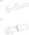
Fig. 1 eine schematische Darstellung einer Knochenschraube, -
Fig. 2 eine schematische Darstellung der Bruchstelle eines Knochens mit einem eingesetzten Bolzen gemäß der Erfindung im Rahmen einer operativen Osteosynthese, -
Fig. 3 ein Ausschnitt eines Querschnittes quer zur Längsachse eines Spenderknochens zur Illustration des Aufbaus eines Osteons und seines Havers-Kanal, -
Fig. 4a eine schematische Darstellung eines erfindungsgemäßen Bolzens im Empfängerknochen mit eingezeichnetem Verlauf der Havers-Kanäle gemäß einer ersten Ausführungsform, -
Fig. 4b eine schematische Darstellung eines erfindungsgemäßen Bolzens im Empfängerknochen mit eingezeichnetem Verlauf der Havers-Kanäle gemäß einer weiteren Ausführungsform, und die -
Fig. 5 eine schematische Darstellung eines Spenderknochens zur Erläuterung des erfindungsgemäßen Verfahrens. - Die vorliegende Erfindung betrifft die Optimierung von Knochenschrauben 1 aus allogenem Knochen, wie sie schematisch in der
Fig. 1 dargestellt ist, hinsichtlich ihrer Eigenschaften im Rahmen der operativen Osteosynthese, insbesondere in Bezug auf ihre Biege- und Scherfestigkeit, sowie ihr Bruchdrehmoment. - Vorzugsweise sind hierfür Knochenschrauben mit symmetrischem Spitzgewinde vorgesehen, um keine Kompression auf die zu verbindenden Knochenteile auszuüben. Da außerdem die Festigkeit der Knochenverbindung im Wesentlichen von der Anzahl der Gewindegänge in der Kortikalis 3 des Empfängerknochens abhängt (siehe
Fig. 2 ), und der Beitrag der Verschraubung entlang des spongiösen Knochens 4 nur gering ist, werden die Knochenschrauben vorzugsweise so ausgeführt, dass sie eine möglichst hohe Anzahl an Gewindegängen pro Millimeter entlang des gesamten Bolzenschaftes aufweisen um sicherzustellen, dass die Kortikalis 3 in Verbindung mit einer entsprechend hohen Zahl an Gewindegängen steht. Bei einem Verhältnis von Gewindetiefe zu Gewindedurchmesser zwischen 0.10 und 0.15 ist hierzu etwa ein Produkt von dieser Verhältniszahl und der Anzahl der Gewindegänge pro Millimeter von 0.10 bis 0.30 vorgesehen. Das symmetrische Spitzgewinde wird außerdem über die gesamte Länge des Bolzenschaftes mit konstantem Gewindedurchmesser geführt, sodass sich eine Knochenschraube 1 wie in derFig. 1 dargestellt ergibt. Die Knochenschraube 1 selbst kann einen Vierkant, Sechskant oder Sternkopf als Schraubenkopf 2 aufweisen (sieheFig. 1 ), der aber lediglich dem Einbringen von Drehmoment im Zuge des Einschraubens dient, und nach Platzierung der Knochenschraube 1 abgeschnitten wird, sodass eine Konfiguration gemäßFig. 2 erreicht wird. - Im Zuge der operativen Osteosynthese wird zunächst die Fixierung und Kompression der zu verbindenden Knochenteile durch entsprechende chirurgische Instrumente sichergestellt. In weiterer Folge wird eine Kernbohrung gesetzt, in das ein Gewinde geschnitten wird. Die erfindungsgemäße Knochenschraube 1 kann nun etwa mit einem Steckschraubenschlüssel mit Drehmoment eingebracht werden, wobei die Knochenschraube 1 die Knochenteile entlang des spongiösen Knochens 4 und der Kortikalis 3 quert, und in einem stabilen Zustand mit vorgegebener Distanz hält, ohne dabei eine Kompression auszuüben, da ein symmetrisch ausgeführtes Spitzgewinde kaum Zugbelastungen zulässt (siehe
Fig. 2 ). Die dargestellte Knochenschraube 1 stellt daher keine Zugschraube dar. Aufgrund der hohen Gewindezahl und der damit verbundenen Reibungskräfte ist aber dennoch hohe Rotationsstabilität der Knochenschraube 1 gegeben. - Zur Erläuterung der erfindungsgemäßen Merkmale wird nun zunächst auf die
Fig. 3 Bezug genommen. DieFig. 3 zeigt einen Ausschnitt eines Querschnittes quer zur Längsachse eines Spenderknochens zur Illustration des Aufbaus eines Osteons 5 und seines Havers-Kanal 6. Ein Osteon 5 besteht dabei aus konzentrisch angeordneten Lamellen, die auch als Speziallamellen bezeichnet werden, dem zentral gelegenen Havers-Kanal 6 und den, zwischen den Lamellen liegenden Osteozyten. Im Havers-Kanal 6 verlaufen Blutgefäße, Bindegewebszellen und -fasern sowie einzelne Nervenfasern. Die einzelnen Osteone 5 sind wiederum durch sogenannte Schaltlamellen 7 miteinander verbunden, wobei die Havers-Kanäle 6 der einzelnen Osteone 5 durch, ebenfalls Blutgefäße enthaltende Querkanäle untereinander verbunden sind, die auch als Volkmann-Kanäle bezeichnet werden (in derFig. 3 nicht ersichtlich). - Osteone 5 und Havers-Kanäle 6 kommen nur in der Kortikalis 3 langer Röhrenknochen vor, wobei die Havers-Kanäle 6 im Wesentlichen in Längsrichtung des Spenderknochens 8 verlaufen. Beim Zuschnitt von Knochenschrauben 1 wird der Spenderknochen 8 in herkömmlicher Weise durch Schnitte quer zu seiner Längserstreckung in mehrere Teilstücke TN unterteilt (siehe auch
Fig. 5 ), aus denen in einem zweiten Verfahrensschritt der Bolzenschaft der Knochenschrauben 1 in einer, zu den Havers-Kanälen 6 im Wesentlichen parallelen Richtung geschnitten wird. Somit verlaufen auch die Havers-Kanäle 6 im Bolzenschaft der Knochenschraube 1 im Wesentlichen parallel zur Längsachse L des Bolzenschaftes, wie anhand derFig. 4a gezeigt ist. Im Rahmen der vorliegenden Erfindung umfasst die Formulierung "im Wesentlichen parallel zur Längsachse L des Bolzenschaftes" auch jenen Fall, wie er in derFig. 4b dargestellt ist, bei dem die Havers-Kanäle 6 in einem maximalen Winkel von 15° schräg zur Längsachse L des Bolzenschaftes der Knochenschraube 1 verlaufen. Auf diese Weise wird erreicht, dass sich vermehrt Öffnungen von Havers-Kanälen 6 entlang der Mantelfläche des Bolzenschaftes befinden, sodass sie für einen Stoffwechselaustausch mit dem Empfängerknochen zugänglich sind, wie anhand der kleinen Pfeile normal auf die Mantelfläche des Bolzenschaftes in derFig. 4b angedeutet wird. Die Integration der Knochenschraube 1 im Empfängerknochen wird dadurch wesentlich beschleunigt, da die Integration der Knochenschraube 1 in den Empfängerknochen und ihre Umwandlung in eigenen Knochen zum beträchtlichen Teil über die Havers-Kanäle 6 verläuft. In weiterer Folge wird in einem dritten Schritt der Bolzenschaft mit einem Außengewinde versehen. - Erfindungsgemäß ist nun vorgesehen, dass ausschließlich jene Teilstücke dem zweiten Verfahrensschritt zur Herstellung einer erfindungsgemäßen Knochenschraube 1 unterzogen werden, deren Grund- und Deckfläche eine Gesamtfläche der Havers-Kanäle 6 von höchstens 10% der Gesamtfläche der jeweiligen Grund- oder Deckfläche aufweist. In der mikroskopischen Analyse der Grund- und Deckfläche eines solchen Teilstückes kann dieses Kriterium selbstredend anhand einer Einheitsfläche im Okular des Mikroskops untersucht werden. Eine mithilfe des erfindungsgemäßen Verfahrens hergestellte Knochenschraube 1 weist somit das erfindungsgemäße Merkmal auf, dass in einem Querschnitt normal zur Längsachse L des Bolzenschaftes die Gesamtfläche der Havers-Kanäle 6 höchstens 10% der Gesamtfläche des Querschnittes einnimmt. Selbstredend könnte auch bei einer Knochenschraube 1 dieses Kriterium anhand einer Einheitsfläche im Okular des Mikroskops untersucht werden.
- Es ist somit lediglich der Spenderknochen 8 entlang seiner Längserstreckung in mehrere Teilstücke TN mit einer Höhe von mehreren Zentimetern, etwa 5-10cm, jeweils mit einem Schnitt quer zur Längserstreckung des Spenderknochens 8 zu zerteilen, wie es anhand der strichlierten Linien in der
Fig. 5 angedeutet ist, und die Grund- und Deckfläche der einzelnen Teilstücke TN entlang der Pfeile derFig. 5 mikroskopisch zu untersuchen. In derFig. 5 sind etwa vier Teilstücke T1, T2, T3 und T4 dargestellt. Die Havers-Kanäle 6 sind in der mikroskopischen Betrachtung als dunkle Flecken ersichtlich, deren Gesamtfläche wie oben erwähnt wurde entweder mithilfe geeigneter Auswertesoftware automatisch ermittelt werden kann, oder mit bloßem Auge mithilfe eines Rasters im Okular des Mikroskops. - Teilstücke TN des Spenderknochens 8, deren Grund- und Deckfläche eine Gesamtfläche der Havers-Kanäle 6 von 10% der Gesamtfläche der jeweiligen Grund- oder Deckfläche übersteigt, werden nicht zur Herstellung von Knochenschrauben 1 herangezogen. Nur jene Teilstücke TN des Spenderknochens 8, deren Grund- und Deckfläche eine Gesamtfläche der Havers-Kanäle 6 von höchstens 10% der Gesamtfläche der jeweiligen Grund- oder Deckfläche aufweist, wird nach dem erfindungsgemäßen Verfahren zur Herstellung von Knochenschrauben 1 verwendet. Auf diese Weise können die durchschnittlichen Biege- und Scherfestigkeiten, sowie Bruchdrehmomente der erfindungsgemäßen Knochenschrauben 1 erhöht werden, und für die einzelne Knochenschraube 1 Mindestwerte für ihre Biege- und Scherfestigkeit, sowie ihr Bruchdrehmoment sichergestellt werden. Dieser Umstand ist für den praktischen Einsatz überaus wichtig, da bislang aufgrund des qualitativ unterschiedlichen Materials von Spenderknochen 8 unterschiedlicher Spender und des qualitativ unterschiedlichen Materials entlang desselben Spenderknochens 8 die Qualität der Knochenschrauben 1 stark variierte und keine definierten Eigenschaften garantiert werden konnten. Für den Chirurgen bestand somit stets die Gefahr, eine minderqualitative bzw. für den konkreten Einsatz ungeeignete Knochenschraube 1 zu verwenden.
- Mithilfe der Erfindung gelingt es Knochenschrauben 1 aus allogenem, kortikalen Knochen so auszuführen, dass Mindestwerte für ihre Biege- und Scherfestigkeit, sowie ihr Bruchdrehmoment sichergestellt werden. Das erfindungsgemäße Kriterium basierend auf dem Flächenverhältnis der Havers-Kanäle 6 zur Gesamtquerschnittsfläche der Knochenschraube 1 stellt dabei nicht nur eine überraschend einfache, sondern auch effektive Maßnahme dar, um die Festigkeit der Knochenschraube 1 zu kontrollieren.
Claims (2)
- Bolzen mit Außengewinde und einem zylindrischen Bolzenschaft aus allogenem, kortikalen Knochenmaterial für die chirurgisch operative Osteosynthese, wobei das Knochenmaterial mit Havers-Kanälen (6) durchzogen ist, dadurch gekennzeichnet, dass in einem Querschnitt normal zur Längsachse (L) des Bolzenschaftes die Gesamtfläche der Havers-Kanäle (6) höchstens 10% der Gesamtfläche des Querschnittes einnimmt.
- Verfahren zur Herstellung eines Bolzens mit Außengewinde und einem zylindrischen Bolzenschaft aus allogenem, kortikalen und mit Havers-Kanälen (6) durchzogenen Knochenmaterial eines Spenderknochens (8) für die chirurgisch operative Osteosynthese, wobei in einem ersten Schritt der Spenderknochen (8) durch Schnitte quer zu seiner Längserstreckung in mehrere Teilstücke (TN) unterteilt wird, aus denen in einem zweiten Verfahrensschritt der Bolzenschaft der Knochenschrauben (1) in einer, zu den Havers-Kanälen (6) im Wesentlichen parallelen Richtung geschnitten wird, und in einem dritten Schritt der Bolzenschaft mit einem Außengewinde versehen wird, dadurch gekennzeichnet, dass ausschließlich jene Teilstücke (TN) dem zweiten Verfahrensschritt unterzogen werden, deren Grund- und Deckfläche eine Gesamtfläche der Havers-Kanäle (6) von höchstens 10% der Gesamtfläche der jeweiligen Grund- oder Deckfläche aufweist.
Applications Claiming Priority (2)
| Application Number | Priority Date | Filing Date | Title |
|---|---|---|---|
| AT5302012A AT511943B1 (de) | 2012-05-04 | 2012-05-04 | Knochenschraube |
| PCT/EP2013/052869 WO2013164107A1 (de) | 2012-05-04 | 2013-02-13 | Knochenschraube |
Publications (2)
| Publication Number | Publication Date |
|---|---|
| EP2844170A1 EP2844170A1 (de) | 2015-03-11 |
| EP2844170B1 true EP2844170B1 (de) | 2017-02-01 |
Family
ID=47710164
Family Applications (1)
| Application Number | Title | Priority Date | Filing Date |
|---|---|---|---|
| EP13703822.0A Active EP2844170B1 (de) | 2012-05-04 | 2013-02-13 | Knochenschraube |
Country Status (4)
| Country | Link |
|---|---|
| EP (1) | EP2844170B1 (de) |
| AT (1) | AT511943B1 (de) |
| ES (1) | ES2622905T3 (de) |
| WO (1) | WO2013164107A1 (de) |
Family Cites Families (5)
| Publication number | Priority date | Publication date | Assignee | Title |
|---|---|---|---|---|
| US4932973A (en) * | 1983-09-30 | 1990-06-12 | El Gendler | Cartilage and bone induction by artificially perforated organic bone matrix |
| US5868749A (en) * | 1996-04-05 | 1999-02-09 | Reed; Thomas M. | Fixation devices |
| US7094239B1 (en) * | 1999-05-05 | 2006-08-22 | Sdgi Holdings, Inc. | Screws of cortical bone and method of manufacture thereof |
| US20090312842A1 (en) * | 2008-06-16 | 2009-12-17 | Predrag Bursac | Assembled Cartilage Repair Graft |
| ES2469872T3 (es) * | 2010-05-07 | 2014-06-20 | Klaus Pastl | Tornillo óseo |
-
2012
- 2012-05-04 AT AT5302012A patent/AT511943B1/de active
-
2013
- 2013-02-13 ES ES13703822.0T patent/ES2622905T3/es active Active
- 2013-02-13 WO PCT/EP2013/052869 patent/WO2013164107A1/de not_active Ceased
- 2013-02-13 EP EP13703822.0A patent/EP2844170B1/de active Active
Non-Patent Citations (1)
| Title |
|---|
| None * |
Also Published As
| Publication number | Publication date |
|---|---|
| WO2013164107A1 (de) | 2013-11-07 |
| AT511943B1 (de) | 2013-04-15 |
| EP2844170A1 (de) | 2015-03-11 |
| AT511943A4 (de) | 2013-04-15 |
| ES2622905T3 (es) | 2017-07-07 |
Similar Documents
| Publication | Publication Date | Title |
|---|---|---|
| AT396326B (de) | Chirurgisches implantat | |
| DE3790560C2 (de) | Osteosynthetischer Nagel | |
| DE3639030A1 (de) | Enossales implantat mit polykapillarer struktur | |
| WO1999062417A1 (de) | Chirurgische blindniete mit schliesselement | |
| AT520250B1 (de) | Knochenschraube | |
| EP2928416A1 (de) | Mehrschichtige distraktionsmembran für knochendefekte | |
| EP4274515B1 (de) | Mehrteiliges implantat mit stützelement und funktionselement | |
| EP0423280A1 (de) | Fixierungssystem für röhrenknochenfrakturen. | |
| EP2384712B1 (de) | Knochenschraube | |
| EP3651685B1 (de) | Knochenaugmentationsstück und bausatz aus knochenaugmentationsstück mit eingesetztem (zahn-) implantat | |
| EP2873390A1 (de) | Halbzeug und hochfestes degradierbares Implantat daraus | |
| EP2844170B1 (de) | Knochenschraube | |
| AT522112B1 (de) | Knochentransplantat | |
| WO2013164106A1 (de) | Knochenschraube | |
| EP2611394B1 (de) | Knochenverankerungs- oder verbindungseinrichtung die einen dehnungsreiz induziert | |
| EP3282984B1 (de) | Knochenschraube | |
| AT507407B1 (de) | Gewindebolzen aus allogenem knochenmaterial | |
| WO1998052489A1 (de) | Biokompatible barrieremembran | |
| EP0408696A1 (de) | Osteosyntheseimplantate | |
| EP3087954A1 (de) | Kieferknochentransplantatanordnung | |
| DE3200156A1 (de) | "schraubverbindung zum komprimieren einer repositionierten knochenfraktur" | |
| DE112021002214T5 (de) | Knochenimplantat | |
| DE102008013648A1 (de) | Implantatsset sowie Verfahren zur Implantation im Knochengewebe | |
| WO2006032362A9 (de) | Partiell resorbierbare osteosynthesen |
Legal Events
| Date | Code | Title | Description |
|---|---|---|---|
| PUAI | Public reference made under article 153(3) epc to a published international application that has entered the european phase |
Free format text: ORIGINAL CODE: 0009012 |
|
| 17P | Request for examination filed |
Effective date: 20141030 |
|
| AK | Designated contracting states |
Kind code of ref document: A1 Designated state(s): AL AT BE BG CH CY CZ DE DK EE ES FI FR GB GR HR HU IE IS IT LI LT LU LV MC MK MT NL NO PL PT RO RS SE SI SK SM TR |
|
| AX | Request for extension of the european patent |
Extension state: BA ME |
|
| DAX | Request for extension of the european patent (deleted) | ||
| 17Q | First examination report despatched |
Effective date: 20151125 |
|
| GRAP | Despatch of communication of intention to grant a patent |
Free format text: ORIGINAL CODE: EPIDOSNIGR1 |
|
| INTG | Intention to grant announced |
Effective date: 20161004 |
|
| GRAS | Grant fee paid |
Free format text: ORIGINAL CODE: EPIDOSNIGR3 |
|
| GRAA | (expected) grant |
Free format text: ORIGINAL CODE: 0009210 |
|
| AK | Designated contracting states |
Kind code of ref document: B1 Designated state(s): AL AT BE BG CH CY CZ DE DK EE ES FI FR GB GR HR HU IE IS IT LI LT LU LV MC MK MT NL NO PL PT RO RS SE SI SK SM TR |
|
| REG | Reference to a national code |
Ref country code: GB Ref legal event code: FG4D Free format text: NOT ENGLISH |
|
| REG | Reference to a national code |
Ref country code: CH Ref legal event code: EP Ref country code: AT Ref legal event code: REF Ref document number: 864901 Country of ref document: AT Kind code of ref document: T Effective date: 20170215 |
|
| REG | Reference to a national code |
Ref country code: IE Ref legal event code: FG4D Free format text: LANGUAGE OF EP DOCUMENT: GERMAN |
|
| REG | Reference to a national code |
Ref country code: FR Ref legal event code: PLFP Year of fee payment: 5 |
|
| REG | Reference to a national code |
Ref country code: DE Ref legal event code: R096 Ref document number: 502013006237 Country of ref document: DE |
|
| REG | Reference to a national code |
Ref country code: CH Ref legal event code: NV Representative=s name: PATENTANWAELTE SCHAAD, BALASS, MENZL AND PARTN, CH |
|
| REG | Reference to a national code |
Ref country code: NL Ref legal event code: MP Effective date: 20170201 |
|
| REG | Reference to a national code |
Ref country code: LT Ref legal event code: MG4D |
|
| REG | Reference to a national code |
Ref country code: ES Ref legal event code: FG2A Ref document number: 2622905 Country of ref document: ES Kind code of ref document: T3 Effective date: 20170707 |
|
| PG25 | Lapsed in a contracting state [announced via postgrant information from national office to epo] |
Ref country code: HR Free format text: LAPSE BECAUSE OF FAILURE TO SUBMIT A TRANSLATION OF THE DESCRIPTION OR TO PAY THE FEE WITHIN THE PRESCRIBED TIME-LIMIT Effective date: 20170201 Ref country code: IS Free format text: LAPSE BECAUSE OF FAILURE TO SUBMIT A TRANSLATION OF THE DESCRIPTION OR TO PAY THE FEE WITHIN THE PRESCRIBED TIME-LIMIT Effective date: 20170601 Ref country code: LT Free format text: LAPSE BECAUSE OF FAILURE TO SUBMIT A TRANSLATION OF THE DESCRIPTION OR TO PAY THE FEE WITHIN THE PRESCRIBED TIME-LIMIT Effective date: 20170201 Ref country code: GR Free format text: LAPSE BECAUSE OF FAILURE TO SUBMIT A TRANSLATION OF THE DESCRIPTION OR TO PAY THE FEE WITHIN THE PRESCRIBED TIME-LIMIT Effective date: 20170502 Ref country code: NO Free format text: LAPSE BECAUSE OF FAILURE TO SUBMIT A TRANSLATION OF THE DESCRIPTION OR TO PAY THE FEE WITHIN THE PRESCRIBED TIME-LIMIT Effective date: 20170501 Ref country code: FI Free format text: LAPSE BECAUSE OF FAILURE TO SUBMIT A TRANSLATION OF THE DESCRIPTION OR TO PAY THE FEE WITHIN THE PRESCRIBED TIME-LIMIT Effective date: 20170201 |
|
| PG25 | Lapsed in a contracting state [announced via postgrant information from national office to epo] |
Ref country code: BG Free format text: LAPSE BECAUSE OF FAILURE TO SUBMIT A TRANSLATION OF THE DESCRIPTION OR TO PAY THE FEE WITHIN THE PRESCRIBED TIME-LIMIT Effective date: 20170501 Ref country code: LV Free format text: LAPSE BECAUSE OF FAILURE TO SUBMIT A TRANSLATION OF THE DESCRIPTION OR TO PAY THE FEE WITHIN THE PRESCRIBED TIME-LIMIT Effective date: 20170201 Ref country code: NL Free format text: LAPSE BECAUSE OF FAILURE TO SUBMIT A TRANSLATION OF THE DESCRIPTION OR TO PAY THE FEE WITHIN THE PRESCRIBED TIME-LIMIT Effective date: 20170201 Ref country code: PL Free format text: LAPSE BECAUSE OF FAILURE TO SUBMIT A TRANSLATION OF THE DESCRIPTION OR TO PAY THE FEE WITHIN THE PRESCRIBED TIME-LIMIT Effective date: 20170201 Ref country code: RS Free format text: LAPSE BECAUSE OF FAILURE TO SUBMIT A TRANSLATION OF THE DESCRIPTION OR TO PAY THE FEE WITHIN THE PRESCRIBED TIME-LIMIT Effective date: 20170201 Ref country code: PT Free format text: LAPSE BECAUSE OF FAILURE TO SUBMIT A TRANSLATION OF THE DESCRIPTION OR TO PAY THE FEE WITHIN THE PRESCRIBED TIME-LIMIT Effective date: 20170601 Ref country code: SE Free format text: LAPSE BECAUSE OF FAILURE TO SUBMIT A TRANSLATION OF THE DESCRIPTION OR TO PAY THE FEE WITHIN THE PRESCRIBED TIME-LIMIT Effective date: 20170201 |
|
| PG25 | Lapsed in a contracting state [announced via postgrant information from national office to epo] |
Ref country code: RO Free format text: LAPSE BECAUSE OF FAILURE TO SUBMIT A TRANSLATION OF THE DESCRIPTION OR TO PAY THE FEE WITHIN THE PRESCRIBED TIME-LIMIT Effective date: 20170201 Ref country code: SK Free format text: LAPSE BECAUSE OF FAILURE TO SUBMIT A TRANSLATION OF THE DESCRIPTION OR TO PAY THE FEE WITHIN THE PRESCRIBED TIME-LIMIT Effective date: 20170201 Ref country code: IT Free format text: LAPSE BECAUSE OF FAILURE TO SUBMIT A TRANSLATION OF THE DESCRIPTION OR TO PAY THE FEE WITHIN THE PRESCRIBED TIME-LIMIT Effective date: 20170201 Ref country code: CZ Free format text: LAPSE BECAUSE OF FAILURE TO SUBMIT A TRANSLATION OF THE DESCRIPTION OR TO PAY THE FEE WITHIN THE PRESCRIBED TIME-LIMIT Effective date: 20170201 Ref country code: EE Free format text: LAPSE BECAUSE OF FAILURE TO SUBMIT A TRANSLATION OF THE DESCRIPTION OR TO PAY THE FEE WITHIN THE PRESCRIBED TIME-LIMIT Effective date: 20170201 |
|
| REG | Reference to a national code |
Ref country code: DE Ref legal event code: R097 Ref document number: 502013006237 Country of ref document: DE |
|
| REG | Reference to a national code |
Ref country code: IE Ref legal event code: MM4A |
|
| PG25 | Lapsed in a contracting state [announced via postgrant information from national office to epo] |
Ref country code: MC Free format text: LAPSE BECAUSE OF FAILURE TO SUBMIT A TRANSLATION OF THE DESCRIPTION OR TO PAY THE FEE WITHIN THE PRESCRIBED TIME-LIMIT Effective date: 20170201 Ref country code: SM Free format text: LAPSE BECAUSE OF FAILURE TO SUBMIT A TRANSLATION OF THE DESCRIPTION OR TO PAY THE FEE WITHIN THE PRESCRIBED TIME-LIMIT Effective date: 20170201 Ref country code: DK Free format text: LAPSE BECAUSE OF FAILURE TO SUBMIT A TRANSLATION OF THE DESCRIPTION OR TO PAY THE FEE WITHIN THE PRESCRIBED TIME-LIMIT Effective date: 20170201 |
|
| PLBE | No opposition filed within time limit |
Free format text: ORIGINAL CODE: 0009261 |
|
| STAA | Information on the status of an ep patent application or granted ep patent |
Free format text: STATUS: NO OPPOSITION FILED WITHIN TIME LIMIT |
|
| PG25 | Lapsed in a contracting state [announced via postgrant information from national office to epo] |
Ref country code: LU Free format text: LAPSE BECAUSE OF NON-PAYMENT OF DUE FEES Effective date: 20170213 |
|
| 26N | No opposition filed |
Effective date: 20171103 |
|
| REG | Reference to a national code |
Ref country code: FR Ref legal event code: PLFP Year of fee payment: 6 |
|
| REG | Reference to a national code |
Ref country code: BE Ref legal event code: MM Effective date: 20170228 |
|
| PG25 | Lapsed in a contracting state [announced via postgrant information from national office to epo] |
Ref country code: IE Free format text: LAPSE BECAUSE OF NON-PAYMENT OF DUE FEES Effective date: 20170213 Ref country code: SI Free format text: LAPSE BECAUSE OF FAILURE TO SUBMIT A TRANSLATION OF THE DESCRIPTION OR TO PAY THE FEE WITHIN THE PRESCRIBED TIME-LIMIT Effective date: 20170201 |
|
| PG25 | Lapsed in a contracting state [announced via postgrant information from national office to epo] |
Ref country code: BE Free format text: LAPSE BECAUSE OF NON-PAYMENT OF DUE FEES Effective date: 20170228 |
|
| PG25 | Lapsed in a contracting state [announced via postgrant information from national office to epo] |
Ref country code: MT Free format text: LAPSE BECAUSE OF FAILURE TO SUBMIT A TRANSLATION OF THE DESCRIPTION OR TO PAY THE FEE WITHIN THE PRESCRIBED TIME-LIMIT Effective date: 20170201 |
|
| REG | Reference to a national code |
Ref country code: AT Ref legal event code: MM01 Ref document number: 864901 Country of ref document: AT Kind code of ref document: T Effective date: 20180213 |
|
| PG25 | Lapsed in a contracting state [announced via postgrant information from national office to epo] |
Ref country code: AT Free format text: LAPSE BECAUSE OF NON-PAYMENT OF DUE FEES Effective date: 20180213 |
|
| PG25 | Lapsed in a contracting state [announced via postgrant information from national office to epo] |
Ref country code: HU Free format text: LAPSE BECAUSE OF FAILURE TO SUBMIT A TRANSLATION OF THE DESCRIPTION OR TO PAY THE FEE WITHIN THE PRESCRIBED TIME-LIMIT; INVALID AB INITIO Effective date: 20130213 |
|
| PG25 | Lapsed in a contracting state [announced via postgrant information from national office to epo] |
Ref country code: CY Free format text: LAPSE BECAUSE OF FAILURE TO SUBMIT A TRANSLATION OF THE DESCRIPTION OR TO PAY THE FEE WITHIN THE PRESCRIBED TIME-LIMIT Effective date: 20170201 |
|
| PG25 | Lapsed in a contracting state [announced via postgrant information from national office to epo] |
Ref country code: MK Free format text: LAPSE BECAUSE OF FAILURE TO SUBMIT A TRANSLATION OF THE DESCRIPTION OR TO PAY THE FEE WITHIN THE PRESCRIBED TIME-LIMIT Effective date: 20170201 |
|
| PG25 | Lapsed in a contracting state [announced via postgrant information from national office to epo] |
Ref country code: TR Free format text: LAPSE BECAUSE OF FAILURE TO SUBMIT A TRANSLATION OF THE DESCRIPTION OR TO PAY THE FEE WITHIN THE PRESCRIBED TIME-LIMIT Effective date: 20170201 |
|
| PG25 | Lapsed in a contracting state [announced via postgrant information from national office to epo] |
Ref country code: AL Free format text: LAPSE BECAUSE OF FAILURE TO SUBMIT A TRANSLATION OF THE DESCRIPTION OR TO PAY THE FEE WITHIN THE PRESCRIBED TIME-LIMIT Effective date: 20170201 |
|
| P01 | Opt-out of the competence of the unified patent court (upc) registered |
Effective date: 20230427 |
|
| PGFP | Annual fee paid to national office [announced via postgrant information from national office to epo] |
Ref country code: CH Payment date: 20250301 Year of fee payment: 13 |
|
| REG | Reference to a national code |
Ref country code: CH Ref legal event code: U11 Free format text: ST27 STATUS EVENT CODE: U-0-0-U10-U11 (AS PROVIDED BY THE NATIONAL OFFICE) Effective date: 20260301 |
|
| PGFP | Annual fee paid to national office [announced via postgrant information from national office to epo] |
Ref country code: GB Payment date: 20260223 Year of fee payment: 14 |
|
| PGFP | Annual fee paid to national office [announced via postgrant information from national office to epo] |
Ref country code: ES Payment date: 20260302 Year of fee payment: 14 |
|
| PGFP | Annual fee paid to national office [announced via postgrant information from national office to epo] |
Ref country code: DE Payment date: 20260218 Year of fee payment: 14 |
|
| PGFP | Annual fee paid to national office [announced via postgrant information from national office to epo] |
Ref country code: FR Payment date: 20260224 Year of fee payment: 14 |