EP2844870B1 - Système et méthode d'arrêt du fonctionnement d'une turbine éolienne - Google Patents
Système et méthode d'arrêt du fonctionnement d'une turbine éolienne Download PDFInfo
- Publication number
- EP2844870B1 EP2844870B1 EP12875758.0A EP12875758A EP2844870B1 EP 2844870 B1 EP2844870 B1 EP 2844870B1 EP 12875758 A EP12875758 A EP 12875758A EP 2844870 B1 EP2844870 B1 EP 2844870B1
- Authority
- EP
- European Patent Office
- Prior art keywords
- wind turbine
- pitch
- pitch rate
- stopping
- controller
- Prior art date
- Legal status (The legal status is an assumption and is not a legal conclusion. Google has not performed a legal analysis and makes no representation as to the accuracy of the status listed.)
- Active
Links
Images


Classifications
-
- F—MECHANICAL ENGINEERING; LIGHTING; HEATING; WEAPONS; BLASTING
- F03—MACHINES OR ENGINES FOR LIQUIDS; WIND, SPRING, OR WEIGHT MOTORS; PRODUCING MECHANICAL POWER OR A REACTIVE PROPULSIVE THRUST, NOT OTHERWISE PROVIDED FOR
- F03D—WIND MOTORS
- F03D7/00—Controlling wind motors
- F03D7/02—Controlling wind motors the wind motors having rotation axis substantially parallel to the air flow entering the rotor
- F03D7/0264—Controlling wind motors the wind motors having rotation axis substantially parallel to the air flow entering the rotor for stopping; controlling in emergency situations
-
- F—MECHANICAL ENGINEERING; LIGHTING; HEATING; WEAPONS; BLASTING
- F03—MACHINES OR ENGINES FOR LIQUIDS; WIND, SPRING, OR WEIGHT MOTORS; PRODUCING MECHANICAL POWER OR A REACTIVE PROPULSIVE THRUST, NOT OTHERWISE PROVIDED FOR
- F03D—WIND MOTORS
- F03D17/00—Monitoring or testing of wind motors, e.g. diagnostics
-
- F—MECHANICAL ENGINEERING; LIGHTING; HEATING; WEAPONS; BLASTING
- F03—MACHINES OR ENGINES FOR LIQUIDS; WIND, SPRING, OR WEIGHT MOTORS; PRODUCING MECHANICAL POWER OR A REACTIVE PROPULSIVE THRUST, NOT OTHERWISE PROVIDED FOR
- F03D—WIND MOTORS
- F03D7/00—Controlling wind motors
- F03D7/02—Controlling wind motors the wind motors having rotation axis substantially parallel to the air flow entering the rotor
- F03D7/022—Adjusting aerodynamic properties of the blades
- F03D7/0224—Adjusting blade pitch
-
- F—MECHANICAL ENGINEERING; LIGHTING; HEATING; WEAPONS; BLASTING
- F05—INDEXING SCHEMES RELATING TO ENGINES OR PUMPS IN VARIOUS SUBCLASSES OF CLASSES F01-F04
- F05B—INDEXING SCHEME RELATING TO WIND, SPRING, WEIGHT, INERTIA OR LIKE MOTORS, TO MACHINES OR ENGINES FOR LIQUIDS COVERED BY SUBCLASSES F03B, F03D AND F03G
- F05B2250/00—Geometry
- F05B2250/70—Shape
- F05B2250/73—Shape asymmetric
-
- F—MECHANICAL ENGINEERING; LIGHTING; HEATING; WEAPONS; BLASTING
- F05—INDEXING SCHEMES RELATING TO ENGINES OR PUMPS IN VARIOUS SUBCLASSES OF CLASSES F01-F04
- F05B—INDEXING SCHEME RELATING TO WIND, SPRING, WEIGHT, INERTIA OR LIKE MOTORS, TO MACHINES OR ENGINES FOR LIQUIDS COVERED BY SUBCLASSES F03B, F03D AND F03G
- F05B2270/00—Control
- F05B2270/10—Purpose of the control system
- F05B2270/107—Purpose of the control system to cope with emergencies
-
- F—MECHANICAL ENGINEERING; LIGHTING; HEATING; WEAPONS; BLASTING
- F05—INDEXING SCHEMES RELATING TO ENGINES OR PUMPS IN VARIOUS SUBCLASSES OF CLASSES F01-F04
- F05B—INDEXING SCHEME RELATING TO WIND, SPRING, WEIGHT, INERTIA OR LIKE MOTORS, TO MACHINES OR ENGINES FOR LIQUIDS COVERED BY SUBCLASSES F03B, F03D AND F03G
- F05B2270/00—Control
- F05B2270/30—Control parameters, e.g. input parameters
- F05B2270/309—Rate of change of parameters
-
- F—MECHANICAL ENGINEERING; LIGHTING; HEATING; WEAPONS; BLASTING
- F05—INDEXING SCHEMES RELATING TO ENGINES OR PUMPS IN VARIOUS SUBCLASSES OF CLASSES F01-F04
- F05B—INDEXING SCHEME RELATING TO WIND, SPRING, WEIGHT, INERTIA OR LIKE MOTORS, TO MACHINES OR ENGINES FOR LIQUIDS COVERED BY SUBCLASSES F03B, F03D AND F03G
- F05B2270/00—Control
- F05B2270/30—Control parameters, e.g. input parameters
- F05B2270/331—Mechanical loads
-
- Y—GENERAL TAGGING OF NEW TECHNOLOGICAL DEVELOPMENTS; GENERAL TAGGING OF CROSS-SECTIONAL TECHNOLOGIES SPANNING OVER SEVERAL SECTIONS OF THE IPC; TECHNICAL SUBJECTS COVERED BY FORMER USPC CROSS-REFERENCE ART COLLECTIONS [XRACs] AND DIGESTS
- Y02—TECHNOLOGIES OR APPLICATIONS FOR MITIGATION OR ADAPTATION AGAINST CLIMATE CHANGE
- Y02E—REDUCTION OF GREENHOUSE GAS [GHG] EMISSIONS, RELATED TO ENERGY GENERATION, TRANSMISSION OR DISTRIBUTION
- Y02E10/00—Energy generation through renewable energy sources
- Y02E10/70—Wind energy
- Y02E10/72—Wind turbines with rotation axis in wind direction
Definitions
- the present subject matter relates generally to wind turbines and, more particularly, to a system and method for stopping the operation of a wind turbine.
- Wind power is considered one of the cleanest, most environmentally friendly energy sources presently available, and wind turbines have gained increased attention in this regard.
- a modern wind turbine typically includes a tower, generator, gearbox, nacelle, and one or more rotor blades.
- the rotor blades capture kinetic energy from wind using known airfoil principles and transmit the kinetic energy through rotational energy to turn a shaft coupling the rotor blades to a gearbox, or if a gearbox is not used, directly to the generator.
- the generator then converts the mechanical energy to electrical energy that may be deployed to a utility grid.
- each rotor blade is subject to deflection and/or twisting due to the aerodynamic wind loads acting on the blade, which results in reaction loads transmitted through the blade.
- the blades are typically pitched during operation. Pitching generally involves rotating each rotor blade about its pitch axis in order to alter the orientation of the rotor blades relative to the wind, thereby adjusting the loading on each rotor blade.
- wind turbine stop events may include controller failures, pitch system failures, other component failures, grid loss, power failure, other emergency situations and/or the like.
- wind turbine control systems utilize a single, uniform stopping procedure in order to halt operation when a wind turbine stop event occurs.
- conventional control systems are designed to pitch the rotor blades to the feather position at a single, predetermined pitch rate regardless of the wind turbine stop event.
- each stop event is typically characterized by unique design driven loads.
- EP 2 108 825 discloses a system and method for reducing rotor loads in a wind turbine upon detection of blade-pitch failure and loss of counter-torque; a brake is used to slow down, but not stop, a rotor.
- DE 10 2005 034 899 discloses a wind energy plant with a rotor with individual pitch devices including a fault detector to detect a fault autonomously and react accordingly. Another prior art example can be found in EP2295793 .
- the present subject matter is directed to a method for stopping the operation of a wind turbine.
- the method may generally include receiving signals associated with at least one operating condition of the wind turbine, analyzing the at least one operating condition with a controller of the wind turbine, implementing a first stopping procedure in order to stop operation of the wind turbine when analysis of the at least one operating condition indicates that a pitch system failure has occurred and implementing a second stopping procedure in order to stop operation of the wind turbine when analysis of the at least one operating condition indicates that a different wind turbine stop event has occurred.
- the present subject matter is directed to a method for stopping the operation of a wind turbine.
- the method may generally include receiving signals associated with at least one operating condition of the wind turbine, analyzing the at least one operating condition with a controller of the wind turbine and implementing a first stopping procedure or a second stopping procedure in order to stop operation of the wind turbine, wherein the first stopping procedure is implemented when analysis of the at least one operating condition indicates that a pitch system failure has occurred.
- the present subject matter is directed to a system for stopping the operation of a wind turbine.
- the system may generally include a sensor configured to monitor at least one operating condition of the wind turbine and a controller communicatively coupled to the sensor.
- the controller may be configured to analyze the at least one operating condition to determine when a wind turbine stop event has occurred.
- the controller may be configured to implement a first stopping procedure in order to stop operation of the wind turbine when it is determined that a pitch system failure has occurred and a second stopping procedure in order to stop operation of the wind turbine when it is determined that a different wind turbine stop event has occurred.
- a wind turbine controller(s) may be configured to implement different stopping procedures for different wind turbine stop events (e.g., pitch system failures, controller failures, other component failures, grid loss, power failure, communications breakdowns and/or other emergency situations).
- the controller(s) may be configured to implement a first stopping procedure when a pitch system failure is detected and a second stopping procedure when another wind turbine stop event is detected.
- the stopping procedure may be specifically tailored to handle the increased asymmetric or unbalanced loads that typically result from the inability to pitch one or more of the rotor blades.
- pitch system failure occurs when a rotor blade is no longer capable of being automatically rotated about its pitch axis.
- pitch system failures may result from the failure of any of the pitch system components (e.g., the failure of a pitch adjustment mechanism and/or a pitch controller), from a communication breakdown (e.g., between a pitch adjustment mechanism and a pitch controller) and/or from any other failures/events that may take away the ability of a wind turbine to automatically pitch one of its rotor blades.
- the present subject matter will generally be described herein with reference to wind turbines having three rotor blades.
- the disclosed stopping procedures for pitch system failures may be utilized when the pitch system for one/two of the rotor blades has failed, thereby leaving two/one rotor blades that may be pitched to the feather position in order to stop the wind turbine.
- the present subject matter may also be utilized with wind turbines having less than three rotor blades or greater than three rotor blades.
- the disclosed stopping procedures may generally be utilized when the pitch system for at least one of the rotor blades remains operational.
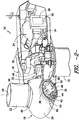
- FIG. 1 illustrates a perspective view of one embodiment of a wind turbine 10.
- the wind turbine 10 generally includes a tower 12 extending from a support surface 14, a nacelle 16 mounted on the tower 12, and a rotor 18 coupled to the nacelle 16.
- the rotor 18 includes a rotatable hub 20 and at least one rotor blade 22 coupled to and extending outwardly from the hub 20.
- the rotor 18 includes three rotor blades 22.
- the rotor 18 may include more or less than three rotor blades 22.
- Each rotor blade 22 may be spaced about the hub 20 to facilitate rotating the rotor 18 to enable kinetic energy to be transferred from the wind into usable mechanical energy, and subsequently, electrical energy.
- the hub 20 may be rotatably coupled to an electric generator 24 ( FIG. 2 ) positioned within the nacelle 16 to permit electrical energy to be produced.
- the wind turbine 10 may also include a turbine control system or main controller 26 centralized within the nacelle 16.
- the main controller 26 may comprise a computer or other suitable processing unit.
- the main controller 26 may include suitable computer-readable instructions that, when implemented, configure the controller 26 to perform various different functions, such as receiving, transmitting and/or executing wind turbine control signals (e.g., pitch commands).
- the main controller 26 may generally be configured to control the various operating modes (e.g., start-up or shut-down sequences) and/or components of the wind turbine 10.
- the controller 26 may be configured to adjust the blade pitch or pitch angle of each rotor blade 22 (i.e., an angle that determines a perspective of the blade 22 with respect to the direction of the wind) about its pitch axis 28 in order to control the rotational speed of the rotor blade 22 as well as the loads acting on the rotor blade 22.
- the main controller 26 may individually control the pitch angle of each rotor blade 22 by transmitting suitable pitch commands to a pitch system 30 ( FIG. 2 ) of the rotor blade 22.
- the controller 26 may generally transmit pitch commands to each pitch system 30 in order to alter the pitch angle of each rotor blade 22 between 0 degrees (i.e., a power position of the rotor blade 22) and 90 degrees (i.e., a feathered position of the rotor blade 22).
- a generator 24 may be disposed within the nacelle 16.
- the generator 24 may be coupled to the rotor 18 for producing electrical power from the rotational energy generated by the rotor 18.
- the rotor 18 may include a rotor shaft 32 coupled to the hub 20 for rotation therewith.
- the rotor shaft 32 may, in turn, be rotatably coupled to a generator shaft 34 of the generator 24 through a gearbox 36.
- the rotor shaft 32 may provide a low speed, high torque input to the gearbox 36 in response to rotation of the rotor blades 22 and the hub 20.
- the gearbox 36 may then be configured to convert the low speed, high torque input to a high speed, low torque output to drive the generator shaft 34 and, thus, the generator 24.
- main controller 26 may also be located within the nacelle 16. As is generally understood, the main controller 26 may be communicatively coupled to any number of the components of the wind turbine 10 in order to control the operation of such components. For example, as indicated above, the main controller 26 may be communicatively coupled to each pitch system 30 of the wind turbine 10 (one of which is shown) to facilitate rotation of each rotor blade 22 about its pitch axis 28.
- each pitch system 30 may include a pitch adjustment mechanism 36 and a pitch controller 38 communicably coupled to the pitch adjustment mechanism 36.
- each pitch adjustment mechanism 36 may include any suitable components and may have any suitable configuration that allows the pitch adjustment mechanism 36 to function as described herein.
- each pitch adjustment mechanism 36 may include a pitch drive motor 40 (e.g., any suitable electric motor), a pitch drive gearbox 42, and a pitch drive pinion 44.
- the pitch drive motor 40 may be coupled to the pitch drive gearbox 42 so that the pitch drive motor 40 imparts mechanical force to the pitch drive gearbox 42.
- the pitch drive gearbox 42 may be coupled to the pitch drive pinion 44 for rotation therewith.
- the pitch drive pinion 44 may, in turn, be in rotational engagement with a pitch bearing 46 coupled between the hub 20 and a corresponding rotor blade 22 such that rotation of the pitch drive pinion 44 causes rotation of the pitch bearing 46.
- rotation of the pitch drive motor 40 drives the pitch drive gearbox 42 and the pitch drive pinion 44, thereby rotating the pitch bearing 46 and the rotor blade 22 about the pitch axis 28.
- each pitch adjustment mechanism 36 may have any other suitable configuration that facilitates rotation of a rotor blade 22 about its pitch axis 28.
- pitch adjustment mechanisms 36 are known that include a hydraulic or pneumatic driven device (e.g., a hydraulic or pneumatic cylinder) configured to transmit rotational energy to the pitch bearing 46, thereby causing the rotor blade 22 to rotate about its pitch axis 28.
- each pitch adjustment mechanism 36 may include a hydraulic or pneumatic driven device that utilizes fluid pressure to apply torque to the pitch bearing 46.
- the operation of the pitch adjustment mechanism 36 for each rotor blade 22 may generally be controlled by the main controller 26 via the individual pitch controller 38 for that rotor blade 22.
- the main controller 26 and each pitch controller 38 may be in communication with one another and/or the pitch adjustment mechanism 36 via a wired connection, such as by using a suitable communicative cable.
- the main controller 26 and each pitch controller 38 may be in communication with one another and/or the pitch adjustment mechanism 36 via a wireless connection, such as by using any suitable wireless communications protocol known in the art.
- each pitch controller 38 may also be configured to independently control the operation of its respective pitch adjustment mechanism 36.
- the pitch controllers 38 may be configured to implement the stopping procedures described herein in order to stop the operation of the wind turbine 10.
- the wind turbine 10 may also include a plurality of sensors 48, 50 for monitoring one or more operating conditions of the wind turbine 10.
- an operating condition of the wind turbine 10 is "monitored” when a sensor 48, 50 is used to determine its present value.
- the term “monitor” and variations thereof are used to indicate that the sensors 48, 50 need not provide a direct measurement of the operating condition being monitored.
- the sensors 48, 50 may be used to generate signals relating to the operating condition being monitored, which can then be utilized by the main controller 26 or other suitable device to determine the actual operating condition.
- the wind turbine 10 may include one or more asymmetric load sensors 48 configured to monitor the amount of asymmetric loading on the wind turbine 10.
- the asymmetric load sensor(s) 48 may comprise one or more strain gauges configured to monitor asymmetric loads by detecting the bending moments caused by such loads.
- a strain gauge may be mounted on or within the main rotor shaft 32 in order to detect loads/moments transmitted through the rotor shaft 32 as a result of asymmetric loads on the wind turbine 10.
- one or more strain gauges may be mounted on or within various other components of the wind turbine 10 (e.g., the rotor blades 22, the hub 20, the tower 12 and/or the like) in order to monitor the asymmetric loading of the wind turbine 10.
- the asymmetric load sensor(s) 48 may comprise one or more position sensors (e.g., proximity sensors) configured to monitor asymmetric loading by detecting changes in the relative positions of wind turbine components. For instance, as shown in FIG.
- one or more position sensors may be disposed at or adjacent to the interface between the hub 20 and the nacelle 16 in order to detect changes in the position of the hub 20 relative to the nacelle 16 (e.g., by configuring the sensor(s) to monitor the distance between the back flange of the hub 20 and the front end of the bearing seat of the nacelle 16).
- the asymmetric load sensor(s) 48 may comprise any other suitable sensors that allow the asymmetric loading of the wind turbine 10 to be monitored.
- the wind turbine 10 may also include additional sensors for monitoring various other operating conditions of the wind turbine 10.
- the wind turbine 10 may include one or more sensors 50 configured to monitor the operation of the pitch adjustment mechanisms 36 (e.g., by monitoring the current input to and/or the torque output of each pitch adjustment mechanism 36).
- the wind turbine 10 may include one or more sensors 50 configured to monitor the operation of the main controller 26 and/or the pitch controllers 38, such as by monitoring the power to and commands transmitted from such controller(s) 26, 38.
- the wind turbine 10 may also include various other sensors for monitoring any other suitable operating conditions of the wind turbine 10, such as the pitch angle of each rotor blade 22, the speed of the rotor 18 and/or the rotor shaft 32, the speed of the generator 24 and/or the generator shaft 34, the torque on the rotor shaft 32 and/or the generator shaft 34, the wind speed and/or wind direction, grid conditions, power input to the components of the wind turbine 10 and/or any other suitable operating conditions.
- any other suitable operating conditions of the wind turbine 10 such as the pitch angle of each rotor blade 22, the speed of the rotor 18 and/or the rotor shaft 32, the speed of the generator 24 and/or the generator shaft 34, the torque on the rotor shaft 32 and/or the generator shaft 34, the wind speed and/or wind direction, grid conditions, power input to the components of the wind turbine 10 and/or any other suitable operating conditions.
- the controller(s) 26, 38 may include one or more processor(s) 52 and associated memory device(s) 54 configured to perform a variety of computer-implemented functions (e.g., performing the methods, steps, calculations and the like disclosed herein).
- processor refers not only to integrated circuits referred to in the art as being included in a computer, but also refers to a controller, a microcontroller, a microcomputer, a programmable logic controller (PLC), an application specific integrated circuit, and other programmable circuits.
- PLC programmable logic controller
- the memory device(s) 54 may generally comprise memory element(s) including, but not limited to, computer readable medium (e.g., random access memory (RAM)), computer readable non-volatile medium (e.g., a flash memory), a floppy disk, a compact disc-read only memory (CD-ROM), a magneto-optical disk (MOD), a digital versatile disc (DVD) and/or other suitable memory elements.
- computer readable medium e.g., random access memory (RAM)
- computer readable non-volatile medium e.g., a flash memory
- CD-ROM compact disc-read only memory
- MOD magneto-optical disk
- DVD digital versatile disc
- Such memory device(s) 54 may generally be configured to store suitable computer-readable instructions that, when implemented by the processor(s) 52, configure the controller(s) 26, 38 to perform various functions including, but not limited to, transmitting suitable control signals to one or more of the pitch adjustment mechanisms 36, monitoring various operating conditions of the wind turbine 10, implementing the disclosed stopping procedures and various other suitable computer-implemented functions.
- the controller(s) 26, 38 may also include a communications module 56 to facilitate communications between the controller 26, 38 and the various components of the wind turbine 10.
- the communications module 56 may serve as an interface to permit the main controller 26 and/or the pitch controllers 38 to transmit pitch commands to each pitch adjustment mechanism 36 for controlling the pitch angle of the rotor blades 22.
- the communications module 56 may include a sensor interface 58 (e.g., one or more analog-to-digital converters) to permit signals transmitted from the sensors 48, 50 of the wind turbine 10 to be converted into signals that can be understood and processed by the processors 53.
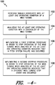
- the method 100 generally includes receiving signals associated with at least one operating condition of a wind turbine 102, analyzing the at least one operating condition with a controller of the wind turbine 104, implementing a first stopping procedure in order to stop operation of the wind turbine when analysis of the at least one operating condition indicates that a pitch system failure has occurred 106 and implementing a second stopping procedure in order to stop operation of the wind turbine when analysis of the at least one operating condition indicates that a different wind turbine stop event has occurred 108.
- the disclosed method 100 may allow for the operation of a wind turbine 10 to be stopped in a more efficient and effective manner than through the use of a single, uniform stopping procedure.
- different stopping procedures may be utilized for different wind turbine stop events, thereby allowing the stopping procedures to be tailored for the specific loads, structural vibrations and/or system dynamics that may occur as a result of each stop event.
- a wind turbine controller(s) 26, 38 may be configured to implement a first stopping procedure when a pitch system failure has occurred and a second stopping procedure when a different wind turbine stop event has occurred.
- the first stopping procedure may be specifically tailored to accommodate the increased asymmetric loading that results from a pitch system failure, thereby ensuring that the wind turbine 10 is stopped in an efficient and effective manner.
- a signal is received that is associated with at least one operating condition of the wind turbine 10.
- the wind turbine 10 may include sensors 48, 50 configured to monitor various operating conditions of the wind turbine 10.
- signals associated with such operating conditions may be transmitted from the sensors 48, 50 to the main controller 26 and/or the pitch controllers 38.
- the controller(s) 26, 38 may be configured to receive signals from the asymmetric load sensors 48 associated with the asymmetric loading of the wind turbine 10.
- the controller(s) 26, 28 may be configured to receive signals associated with other operating conditions that relate to different wind turbine stop events. For example, inputs received from sensors may allow the controller(s) 26, 38 to determine that a controller failure, other component failure, grid loss, power failure, communications breakdowns and/or other emergency event has occurred.
- the operating condition(s) of the wind turbine 10 may be analyzed by the controller(s) 26, 38 to determine whether a wind turbine stop event has occurred.
- the controller(s) 26, 38 may be configured to compare the actual asymmetric loading of the wind turbine 10 (obtained via the sensors 48) to a predetermined asymmetric loading threshold. If the actual asymmetric loading is equal to or exceeds the predetermined asymmetric loading threshold, the controller(s) 26, 38 may determine that the pitch system 30 for one or more of the rotor blades 22 has failed.
- the controller(s) 26, 38 may be configured to analyze sensor inputs related to the operation of the pitch adjustment mechanisms 36 (e.g., via sensors 50) and/or any other suitable components of the wind turbine 10 in order to determine whether a pitch system failure has occurred.
- the predetermined asymmetric loading threshold may generally vary from wind turbine 10 to wind turbine 10 based on numerous factors including but, not limited to, the configuration of the wind turbine 10 (e.g., rotor size), the operating conditions of the wind turbine 10 and/or the like. However, it is well within the purview of one of ordinary skill in the art to determine the asymmetric loading threshold for a particular wind turbine 10 based on the configuration of the wind turbine 10 and using known data relating to the wind turbine 10 (e.g., historical data, observed data, predicted/simulated data).
- the operation of the wind turbine 10 may be stopped according to a first stopping procedure when it is determined that a pitch system failure has occurred and according to a second stopping procedure when it is determined that a different wind turbine stop event has occurred.
- the controller(s) 26, 38 may be configured to implement the first stopping procedure.
- the controller(s) 26, 38 may be configured to implement the second stopping procedure.
- both the first and second stopping procedures may include pitching the rotor blades 22 from the power position to the feather position in order to stop the rotation of the rotor 18.
- the second stopping procedure i.e., for a non-pitch system failure stop event
- all of the rotor blades 22 may be pitched to the feather position.
- the pitch system 30 of one or two of the rotor blades 22 has failed, only the remaining blade(s) 22 may be pitched to the feather position in order to stop the operation of the wind turbine 10.
- the first stopping procedure must account for the fact that at least one of the rotor blades 22 will remain in the power position as the wind turbine 10 is being stopped.
- the first stopping procedure may differ from the second stopping procedure with respect to the rate at which the rotor blades 22 are pitched.
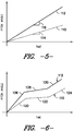
- FIG. 5 illustrates one example of how the pitch of the rotor blades 22 may be adjusted over time using the first stopping procedure (indicated by the dashed line 110) and the second stopping procedure (indicated by the solid line 112).
- the pitch of the rotor blades 22 may be adjusted according to a first pitch rate (indicated by the slope 114 of line 110) for the first stopping procedure 110 and according to second pitch rate (indicated by the slope 116 of line 112) for the second stopping procedure 112.
- the first pitch rate 114 may be less or slower than the second pitch rate 116 due to the fact that less than all of the rotor blades 22 are being pitched.
- the blades 22 may be pitched at a faster rate without introducing additional asymmetric loads and/or undesirable structural vibrations and/or system dynamics.
- first and second pitch rates 114, 116 may generally correspond to any suitable rates at which the rotor blades 22 may be pitched during the first and second stopping procedures 110, 112 without introducing significant loads and/or vibrations onto the wind turbine 10.
- the first pitch rate 114 may range from about 0.5 degrees/second (°/s) to about 5°/s, such as from about 1°/s to about 4°/s or from about 2°/s to about 3°/s and all other subranges therebetween.
- the second pitch rate 116 may range from about 5°/s to about 10°/s, such as from about 6°/s to about 9°/s or from about 7°/s to about 8°/s and all other subranges therebetween.
- the first and second stopping procedures 110, 112 utilized pitch rates that vary over time, such as by adjusting the pitch rates two or more times as a wind turbine 10 is being stopped.
- the first and second stopping procedures 110, 112 may be configured to adjust the pitch of the rotor blades 22 according to a triple pitch rate schedule.
- the pitch of the rotor blades 22 may be initially adjusted at a relatively high pitch rate (indicated by line segment 120 for the first stopping procedure 110 and line segment 126 for the second stopping procedure 112), followed by adjustment of the pitch at a lower pitch rate (indicated by line segment 122 for the first stopping procedure 110 and line segment 128 for the second stopping procedure 112) and then again at a relatively high pitch rate (indicated by line segment 124 for the first stopping procedure 110 and line segment 130 for the second stopping procedure 112).
- the initial higher pitch rates 120, 126 may generally allow the for the rotational speed/energy of the wind turbine 10 to be substantially reduced over a short period of time.
- the pitch rates may be reduced for a period of time. Once the risk of exciting structural vibrations and/or other system dynamics is minimized, the pitch rates may then be increased to quickly stop the operation of the wind turbine 10.
- the higher pitch rates 120, 124 for the first stopping procedure may generally be less than the higher pitch rates 126, 130 for the second stopping procedure.
- the initial pitch rate 120 for the first stopping procedure 110 may range from about 3 °/s to about 7 °/s, such as from about 4.5 °/s to about 6.5 °/s or from about 5 °/s to about 6 °/s and all other subranges therebetween, while the initial pitch rate 126 for the second stopping procedure 112 may range from about 5 °/s to about 9 °/s, such as from about 6.5 °/s to about 8.5 °/s or from about 7 °/s to about 8 °/s and all other subranges therebetween.
- the reduced pitch rate 122 for the first stopping procedure 110 may range from about 0.5 °/s to about 5 °/s, such as from about 1 °/s to about 3.5 °/s or from about 2 °/s to about 3 °/s and all other subranges therebetween, and the reduced pitch rate 128 for the second stopping procedure 112 may range from about 0.5 °/s to about 5.5 °/s, such as from about 1 °/s to about 3.5 °/s or from about 2 °/s to about 3 °/s and all other subranges therebetween.
- the loading on the wind turbine 10 during execution of the stopping procedures 110, 112 may be adjusted.
- three test cases were evaluated with different high pitch rates (indicated by line 120) and low pitch rates (indicated by line 122) for the first stopping procedure 110.
- a rotor blade 22 was pitched at a high pitch rate of 5.5 °/s for 1.2 seconds and then at a low pitch rate of 2.5 °/s for 1.9 seconds.
- the rotor blade 22 was pitched at a high pitch rate of 5.5 °/s for 1.2 seconds and then at a low pitch rate of 0.5 °/s for 1.9 seconds.
- the rotor blade 22 was pitched at a high pitch rate of 3.5 °/s for 1.2 seconds and then at a low pitch rate of 2.5 °/s for 1.9 seconds.
- the loading on the wind turbine 10 was then evaluated for each test case. It was found that the loads in second test case were about 8% smaller than the loads in the first test case. In addition, the loads in the third test case where about 4% smaller than the loads in the first test case.
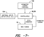
- FIG. 7 illustrates a control diagram that may be utilized to implement a stopping procedure when it is determined that a pitch system failure has occurred.
- a closed-loop algorithm e.g., a closed-loop PID or other suitable closed-loop control algorithm
- a closed-loop algorithm may be utilized to continuously monitor one or more of the operating conditions of the wind turbine 10 and, based on such monitored operating conditions, make adjustments to the manner in which the rotor blade(s) 22 are pitched during the stopping procedure.
- the controller(s) 26, 38 may be configured to initially pitch the rotor blade(s) 22 at a predetermined pitch rate (e.g., by sending suitable pitch commands to the pitch adjustment mechanisms 36). As the blades 22 are being pitched, the controller(s) 26, 38 may be configured to receive inputs associated with the asymmetric loading of the wind turbine 10 (e.g., via the asymmetric load sensor(s) 48). Thus, by continuously monitoring the asymmetric loading of the wind turbine 10, the rate at which the rotor blade(s) are pitched may be dynamically adjusted based on any variances in the loading. For example, as shown in FIG.
- the controller(s) 26, 38 may be configured to continuously compare the monitored asymmetric loading to the predetermined asymmetric loading threshold (indicated by box 132). Thus, in the event that the monitored asymmetric loading is equal to or exceeds the asymmetric loading threshold 132, the controller(s) 26, 38 may be able to reduce the rate at which the rotor blade(s) 22 are being pitched (e.g., by transmitting suitable pitch commands to the pitch adjustment mechanism(s) 36) in order to reduce the likelihood of the loads being increased and/or structural vibrations being introduced.
- the controller(s) 26, 38 may be able to increase the rate at which the rotor blades 22 are being pitched to permit the rotational speed of the rotor 18 to be reduced at a faster rate.
- controller(s) 26, 38 may also be configured to receive additional inputs (indicated by box 134) to facilitate controlling the pitch of the rotor blades 22.
- the controller(s) 26, 38 may be configured to receive inputs related to the rotor speed.
- the controller(s) 26, 38 may be configured to control the pitch of the rotor blades 22 based on both the rotor speed and the asymmetric loading of the wind turbine 10.
- control logic of the controller(s) 26, 38 may be configured to pitch the rotor blades 22 in order to satisfy a predetermined speed ramp-down rate, with the asymmetric loading inputs being used to override such control when the loading is equal to or exceeds the asymmetric loading threshold 132.
- the present subject matter is also directed to a system for stopping the operation of a wind turbine 10.
- the system may include a sensor 48, 50 configured to monitor at least one operating condition of the wind turbine 10 and a controller 26, 38 communicatively coupled to the sensor 48, 50.
- the controller 26, 38 may be configured to analyze the operating condition(s) to determine when a wind turbine stop event has occurred.
- the controller 26, 38 may be configured to implement a first stopping procedure in order to stop operation of the wind turbine 10 when it is determined that a pitch system failure has occurred and a second stopping procedure in order to stop operation of the wind turbine 10 when it is determined that a different wind turbine stop event has occurred.
Landscapes
- Engineering & Computer Science (AREA)
- Life Sciences & Earth Sciences (AREA)
- Sustainable Development (AREA)
- Sustainable Energy (AREA)
- Chemical & Material Sciences (AREA)
- Combustion & Propulsion (AREA)
- Mechanical Engineering (AREA)
- General Engineering & Computer Science (AREA)
- Physics & Mathematics (AREA)
- Fluid Mechanics (AREA)
- Wind Motors (AREA)
Claims (11)
- Méthode (100) d'arrêt du fonctionnement d'une turbine éolienne, la méthode comprenant :recevoir (102) des signaux associés à au moins une condition de fonctionnement de la turbine éolienne ;analyser (104) l'au moins une condition de fonctionnement avec une unité de commande de la turbine éolienne ;mettre en œuvre (106) une première procédure d'arrêt ou une deuxième procédure d'arrêt pour arrêter le fonctionnement de la turbine éolienne,dans laquelle la première procédure d'arrêt (106) est mise en œuvre lorsque l'analyse de l'au moins une condition de fonctionnement indique qu'un échec du système de tangage s'est produit, la première procédure d'arrêt comprenant le tangage d'au moins une pale de rotor opérationnelle (22) de la turbine éolienne (10) à un premier taux de tangage.dans laquelle la deuxième procédure d'arrêt est mise en œuvre lorsque l'analyse de l'au moins une condition de fonctionnement indique qu'un événement différent d'arrêt de turbine éolienne s'est produit, la deuxième procédure d'arrêt comprenant des pales de rotor de tangage (22) de la turbine éolienne (10) à un deuxième taux de tangage.
- Méthode (100) selon la revendication 1, dans laquelle la réception (102) de signaux associés à au moins une condition de fonctionnement d'une turbine éolienne (10) comprend la réception de signaux associés à un chargement asymétrique de la turbine éolienne (10).
- Méthode (100) selon la revendication 2, dans laquelle l'analyse (104) de l'au moins une condition de fonctionnement avec une unité de commande (26) de la turbine éolienne (10) comprend la comparaison du chargement asymétrique de la turbine éolienne (10) à un seuil de charge asymétrique prédéterminé.
- Méthode (100) selon la revendication 3, dans laquelle la mise en œuvre (106) d'une première procédure d'arrêt afin d'arrêter le fonctionnement de la turbine éolienne (10) lors de l'analyse de l'au moins une condition de fonctionnement indique qu'un échec de système de tangage (36) s'est produit comprend la mise en œuvre de la première procédure d'arrêt lorsque le chargement asymétrique de la turbine éolienne (10) est égal à ou dépasse le seuil prédéterminé de chargement asymétrique.
- Méthode (100) selon la revendication 4, comprenant en outre :surveiller en continu le chargement asymétrique de la turbine éolienne (10) ; etrégler un taux de tangage de la première procédure d'arrêt sur la base des variations de la charge asymétrique.
- Méthode (100) selon la revendication 1, dans laquelle le premier taux de tangage comprend un taux de tangage élevé et un bas taux de tangage, le taux de tangage élevé allant de 3 °/s à 7 °/s et le bas taux de tangage allant de 0,5 °/s à 5 °/s.
- Méthode (100) selon la revendication 1, dans laquelle le deuxième taux de tangage comprend un taux de tangage élevé et un bas taux de tangage, le taux de tangage élevé allant de 5 °/s à 9 °/s et le bas taux de tangage allant de 0,5 °/s à 5 °/s.
- Méthode (100) selon la revendication 1, dans laquelle les premier et deuxième taux de tangage varient avec le temps selon un programme à taux de tangage triple.
- Système d'arrêt du fonctionnement d'une turbine éolienne (10), le système comprenant :un capteur (134) configuré pour surveiller au moins une condition de fonctionnement de la turbine éolienne (10) ; etune unité de commande (26, 38) couplée par communication avec le capteur (134), l'unité de commande (26, 38) étant configurée pour analyser l'au moins une condition de fonctionnement pour déterminer lorsqu'un événement d'arrêt de turbine éolienne s'est produit, l'unité de commande (26, 38) étant en outre configurée pour mettre en œuvre une première procédure d'arrêt afin d'arrêter le fonctionnement de la turbine éolienne (10) lorsqu'il est déterminé qu'un échec de système de tangage (36) s'est produit et une deuxième procédure d'arrêt afin d'arrêter le fonctionnement de la turbine éolienne (10) lorsqu'il est déterminé qu'un événement différent d'arrêt de turbine éolienne s'est produit,un mécanisme de réglage de tangage (36), l'unité de commande (26, 38) étant configurée pour transmettre des commandes de tangage au mécanisme de réglage de tangage (36) afin de mettre en œuvre les première et deuxième procédures d'arrêt,dans laquelle l'unité de commande (26, 38) est configurée pour commander le mécanisme de réglage de tangage (36) de telle sorte qu'au moins une pale de rotor opérationnelle (22) de la turbine éolienne (10) est inclinée à un premier taux de tangage lorsque la première procédure d'arrêt est mise en œuvre et que les pales de rotor (22) de la turbine éolienne (10) sont inclinées à un deuxième taux de tangage lorsque la deuxième procédure d'arrêt est mise en œuvre, le premier taux de tangage différant du deuxième taux de tangage.
- Système selon la revendication 9, dans lequel le premier taux de tangage comprend un taux de tangage élevé et un bas taux de tangage, le taux de tangage élevé allant de 3 °/s à 7 °/ s et le bas taux de tangage allant de 0,5 °/s à 5 °/s.
- Système selon la revendication 9, dans lequel le deuxième taux de tangage comprend un taux de tangage élevé et un bas taux de tangage, le taux de tangage élevé allant de 5 °/s à 9 °/s et le bas taux de tangage allant de 0,5 °/s à 5 °/s.
Applications Claiming Priority (1)
| Application Number | Priority Date | Filing Date | Title |
|---|---|---|---|
| PCT/CN2012/074975 WO2013163795A1 (fr) | 2012-05-02 | 2012-05-02 | Système et méthode d'arrêt du fonctionnement d'une turbine éolienne |
Publications (3)
| Publication Number | Publication Date |
|---|---|
| EP2844870A1 EP2844870A1 (fr) | 2015-03-11 |
| EP2844870A4 EP2844870A4 (fr) | 2015-12-30 |
| EP2844870B1 true EP2844870B1 (fr) | 2020-07-01 |
Family
ID=49514177
Family Applications (1)
| Application Number | Title | Priority Date | Filing Date |
|---|---|---|---|
| EP12875758.0A Active EP2844870B1 (fr) | 2012-05-02 | 2012-05-02 | Système et méthode d'arrêt du fonctionnement d'une turbine éolienne |
Country Status (5)
| Country | Link |
|---|---|
| US (1) | US9726147B2 (fr) |
| EP (1) | EP2844870B1 (fr) |
| CA (1) | CA2871278C (fr) |
| ES (1) | ES2820432T3 (fr) |
| WO (1) | WO2013163795A1 (fr) |
Families Citing this family (16)
| Publication number | Priority date | Publication date | Assignee | Title |
|---|---|---|---|---|
| EP2778602B1 (fr) * | 2013-03-14 | 2015-10-14 | Siemens Aktiengesellschaft | Dispositif pour mesurer la déviation d'une pale d'une éolienne |
| ES2683210T3 (es) * | 2013-04-22 | 2018-09-25 | Vestas Wind Systems A/S | Método para controlar una turbina eólica durante la parada |
| US10378517B2 (en) * | 2014-03-04 | 2019-08-13 | Steffen Bunge | Method for replacing the blades of a wind turbine to maintain safe operation |
| EP2937559A1 (fr) * | 2014-04-25 | 2015-10-28 | Moog Unna GmbH | Processus de secours par mise en drapeau |
| CN105332855B (zh) | 2014-06-11 | 2019-06-28 | 通用电气公司 | 用于风力涡轮机的控制方法和控制系统 |
| JP6282187B2 (ja) * | 2014-07-03 | 2018-02-21 | 株式会社日立製作所 | 風車及びその停止方法 |
| CN104179636B (zh) * | 2014-07-25 | 2017-02-15 | 北车风电有限公司 | 一种防止风力发电机组飞车的方法 |
| EP3362683B1 (fr) * | 2015-10-14 | 2020-04-22 | Vestas Wind Systems A/S | Procédé pour commander une force d'un système de pas variable hydraulique |
| US10890159B2 (en) * | 2016-08-17 | 2021-01-12 | Vestas Wind Systems A/S | Dynamic controlled wind turbine shutdown |
| US10927812B2 (en) * | 2019-02-19 | 2021-02-23 | General Electric Company | Method of dynamically adjusting a rate of change of a rotor speed set point during wind turbine shutdown |
| CN112145343B (zh) * | 2019-06-27 | 2022-07-05 | 北京金风科创风电设备有限公司 | 变桨系统收桨控制方法、装置及计算机可读存储介质 |
| WO2021098925A1 (fr) * | 2019-11-21 | 2021-05-27 | Vestas Wind Systems A/S | Arrêt d'un rotor d'éolienne sur la base d'un signal d'angle de calage stocké |
| CN113404639B (zh) * | 2021-08-05 | 2022-10-18 | 中国船舶重工集团海装风电股份有限公司 | 一种风电机组载荷友好型卡桨停机方法及系统 |
| CN113586333B (zh) * | 2021-08-16 | 2022-12-13 | 许昌许继风电科技有限公司 | 一种风电变桨系统手操控制盒及手操控制方法 |
| CN114934875B (zh) * | 2022-05-30 | 2025-07-18 | 国电联合动力技术有限公司 | 风电机组紧急停机降载控制方法、装置、电子设备及介质 |
| EP4632218A1 (fr) * | 2024-04-09 | 2025-10-15 | Wobben Properties GmbH | Procédé de commande d'une éolienne dans un arrêt de sécurité |
Citations (1)
| Publication number | Priority date | Publication date | Assignee | Title |
|---|---|---|---|---|
| EP2295793A2 (fr) * | 2009-09-11 | 2011-03-16 | General Electric Company | Système et méthode pour déterminer une limite d'interruption pour une éolienne |
Family Cites Families (15)
| Publication number | Priority date | Publication date | Assignee | Title |
|---|---|---|---|---|
| US7004724B2 (en) * | 2003-02-03 | 2006-02-28 | General Electric Company | Method and apparatus for wind turbine rotor load control based on shaft radial displacement |
| US7118339B2 (en) * | 2004-06-30 | 2006-10-10 | General Electric Company | Methods and apparatus for reduction of asymmetric rotor loads in wind turbines |
| DE102005034899A1 (de) * | 2005-07-26 | 2007-02-01 | Repower Systems Ag | Windenergieanlage mit Einzelpitcheinrichtungen |
| US7488155B2 (en) * | 2005-11-18 | 2009-02-10 | General Electric Company | Method and apparatus for wind turbine braking |
| US8240990B2 (en) | 2007-12-06 | 2012-08-14 | General Electric Company | Apparatus and method for reducing asymmetric rotor loads in wind turbines during shutdown |
| US7944067B2 (en) * | 2008-04-01 | 2011-05-17 | General Electric Company | System and method for reducing rotor loads in a wind turbine upon detection of blade-pitch failure and loss of counter-torque |
| CN101715515A (zh) * | 2008-05-16 | 2010-05-26 | 三菱重工业株式会社 | 风车的间距角控制装置及其方法 |
| CN201326512Y (zh) | 2008-12-24 | 2009-10-14 | 华锐风电科技有限公司 | 风力发电机组变桨系统控制装置 |
| US8178986B2 (en) * | 2009-03-18 | 2012-05-15 | General Electric Company | Wind turbine operation system and method |
| EP2256342B8 (fr) | 2009-05-28 | 2013-10-23 | Nordex Energy GmbH | Procédé de freinage d'urgence d'une éolienne et éolienne dotée d'un réglage de pale de rotor pour le freinage d'urgence |
| ES2541835T3 (es) * | 2010-02-08 | 2015-07-27 | Mitsubishi Heavy Industries, Ltd. | Generador eléctrico de propulsión eólica y procedimiento de control del ángulo de paso de pala para el mismo |
| ES2633816T3 (es) * | 2010-08-23 | 2017-09-25 | Vestas Wind Systems A/S | Método de operación de una turbina eólica y turbina eólica |
| CN102022260B (zh) * | 2010-11-24 | 2012-08-01 | 南京飓能电控自动化设备制造有限公司 | 基于超级电容的冗余电变桨系统 |
| US8430632B2 (en) * | 2011-12-22 | 2013-04-30 | General Electric Company | System and method for pitching a rotor blade in a wind turbine |
| WO2013159779A1 (fr) * | 2012-04-23 | 2013-10-31 | Vestas Wind Systems A/S | Procédé de commande d'une turbine éolienne pendant un arrêt |
-
2012
- 2012-05-02 EP EP12875758.0A patent/EP2844870B1/fr active Active
- 2012-05-02 CA CA2871278A patent/CA2871278C/fr active Active
- 2012-05-02 US US14/381,687 patent/US9726147B2/en active Active
- 2012-05-02 ES ES12875758T patent/ES2820432T3/es active Active
- 2012-05-02 WO PCT/CN2012/074975 patent/WO2013163795A1/fr not_active Ceased
Patent Citations (1)
| Publication number | Priority date | Publication date | Assignee | Title |
|---|---|---|---|---|
| EP2295793A2 (fr) * | 2009-09-11 | 2011-03-16 | General Electric Company | Système et méthode pour déterminer une limite d'interruption pour une éolienne |
Also Published As
| Publication number | Publication date |
|---|---|
| EP2844870A1 (fr) | 2015-03-11 |
| CA2871278C (fr) | 2018-06-12 |
| CA2871278A1 (fr) | 2013-11-07 |
| EP2844870A4 (fr) | 2015-12-30 |
| US9726147B2 (en) | 2017-08-08 |
| ES2820432T3 (es) | 2021-04-21 |
| US20150110596A1 (en) | 2015-04-23 |
| WO2013163795A1 (fr) | 2013-11-07 |
Similar Documents
| Publication | Publication Date | Title |
|---|---|---|
| EP2844870B1 (fr) | Système et méthode d'arrêt du fonctionnement d'une turbine éolienne | |
| EP2698534B1 (fr) | Système et procédé de freinage d'un rotor d'éolienne en cas de survitesse | |
| US10337495B2 (en) | System and method for reducing vortex-induced tower vibrations of a wind turbine | |
| EP3597905B1 (fr) | Système et procédé de détection d'un défaut de pas dans une éolienne par l'intermédiaire de la surveillance de la tension, du courant, du couple ou de la force | |
| EP3597904B1 (fr) | Système et procédé de réduction des charges d'éolienne par orientation de la nacelle dans une position prédéterminée basée sur un déséquilibre de rotor | |
| US20120134807A1 (en) | Method for preventing rotor overspeed of a wind turbine | |
| EP3597910B1 (fr) | Système et procédé permettant de réduire des charges pendant un état de ralenti ou de stationnement d'une éolienne avec une pale de rotor bloquée | |
| DK2418380T3 (en) | Blade angle control device for wind turbine. | |
| EP3581795B1 (fr) | Système et procédé de commande d'éolienne pour minimiser les dommages de pales de rotor | |
| EP3643915B1 (fr) | Système et procédé d'application d'un frein pour une éolienne | |
| CA2923290C (fr) | Commande d'eolienne au moyen d'un controleur de signal | |
| EP2963286A1 (fr) | Éolienne et procédé pour l'arrêter | |
| US20110210551A1 (en) | Method and system for testing a mechanical brake of a wind rotor shaft of a wind turbine | |
| US20130243590A1 (en) | Systems and methods for determining thrust on a wind turbine | |
| EP3091227B1 (fr) | Commande de lacet autonome pour une éolienne | |
| EP3892850B1 (fr) | Système et procédé pour atténuer les charges agissant sur une pale de rotor d'une éolienne | |
| JP2019078223A (ja) | 水平軸風車の制御装置、水平軸風車、水平軸風車の制御プログラム | |
| EP3699421B1 (fr) | Procédé d'ajustement dynamique d'un taux de changement d'un point de réglage de vitesse de rotor lors de l'arrêt d'une éolienne | |
| EP3597906B1 (fr) | Système et procédé de réduction des charges d'une éolienne lors d'un blocage de pale de rotor |
Legal Events
| Date | Code | Title | Description |
|---|---|---|---|
| PUAI | Public reference made under article 153(3) epc to a published international application that has entered the european phase |
Free format text: ORIGINAL CODE: 0009012 |
|
| 17P | Request for examination filed |
Effective date: 20141202 |
|
| AK | Designated contracting states |
Kind code of ref document: A1 Designated state(s): AL AT BE BG CH CY CZ DE DK EE ES FI FR GB GR HR HU IE IS IT LI LT LU LV MC MK MT NL NO PL PT RO RS SE SI SK SM TR |
|
| AX | Request for extension of the european patent |
Extension state: BA ME |
|
| DAX | Request for extension of the european patent (deleted) | ||
| RA4 | Supplementary search report drawn up and despatched (corrected) |
Effective date: 20151127 |
|
| RIC1 | Information provided on ipc code assigned before grant |
Ipc: F03D 11/00 20060101ALI20151123BHEP Ipc: F03D 7/02 20060101AFI20151123BHEP |
|
| STAA | Information on the status of an ep patent application or granted ep patent |
Free format text: STATUS: EXAMINATION IS IN PROGRESS |
|
| 17Q | First examination report despatched |
Effective date: 20180601 |
|
| GRAP | Despatch of communication of intention to grant a patent |
Free format text: ORIGINAL CODE: EPIDOSNIGR1 |
|
| STAA | Information on the status of an ep patent application or granted ep patent |
Free format text: STATUS: GRANT OF PATENT IS INTENDED |
|
| RIC1 | Information provided on ipc code assigned before grant |
Ipc: F03D 80/00 20160101ALI20190730BHEP Ipc: F03D 17/00 20160101ALI20190730BHEP Ipc: F03D 7/02 20060101AFI20190730BHEP |
|
| INTG | Intention to grant announced |
Effective date: 20190827 |
|
| GRAJ | Information related to disapproval of communication of intention to grant by the applicant or resumption of examination proceedings by the epo deleted |
Free format text: ORIGINAL CODE: EPIDOSDIGR1 |
|
| STAA | Information on the status of an ep patent application or granted ep patent |
Free format text: STATUS: EXAMINATION IS IN PROGRESS |
|
| GRAP | Despatch of communication of intention to grant a patent |
Free format text: ORIGINAL CODE: EPIDOSNIGR1 |
|
| STAA | Information on the status of an ep patent application or granted ep patent |
Free format text: STATUS: GRANT OF PATENT IS INTENDED |
|
| INTC | Intention to grant announced (deleted) | ||
| INTG | Intention to grant announced |
Effective date: 20200123 |
|
| GRAS | Grant fee paid |
Free format text: ORIGINAL CODE: EPIDOSNIGR3 |
|
| GRAA | (expected) grant |
Free format text: ORIGINAL CODE: 0009210 |
|
| STAA | Information on the status of an ep patent application or granted ep patent |
Free format text: STATUS: THE PATENT HAS BEEN GRANTED |
|
| AK | Designated contracting states |
Kind code of ref document: B1 Designated state(s): AL AT BE BG CH CY CZ DE DK EE ES FI FR GB GR HR HU IE IS IT LI LT LU LV MC MK MT NL NO PL PT RO RS SE SI SK SM TR |
|
| REG | Reference to a national code |
Ref country code: GB Ref legal event code: FG4D |
|
| REG | Reference to a national code |
Ref country code: CH Ref legal event code: EP Ref country code: AT Ref legal event code: REF Ref document number: 1286416 Country of ref document: AT Kind code of ref document: T Effective date: 20200715 |
|
| REG | Reference to a national code |
Ref country code: DE Ref legal event code: R096 Ref document number: 602012071069 Country of ref document: DE |
|
| REG | Reference to a national code |
Ref country code: IE Ref legal event code: FG4D |
|
| REG | Reference to a national code |
Ref country code: DK Ref legal event code: T3 Effective date: 20201002 |
|
| REG | Reference to a national code |
Ref country code: LT Ref legal event code: MG4D |
|
| PG25 | Lapsed in a contracting state [announced via postgrant information from national office to epo] |
Ref country code: BG Free format text: LAPSE BECAUSE OF FAILURE TO SUBMIT A TRANSLATION OF THE DESCRIPTION OR TO PAY THE FEE WITHIN THE PRESCRIBED TIME-LIMIT Effective date: 20201001 |
|
| REG | Reference to a national code |
Ref country code: NL Ref legal event code: MP Effective date: 20200701 |
|
| REG | Reference to a national code |
Ref country code: AT Ref legal event code: MK05 Ref document number: 1286416 Country of ref document: AT Kind code of ref document: T Effective date: 20200701 |
|
| PG25 | Lapsed in a contracting state [announced via postgrant information from national office to epo] |
Ref country code: FI Free format text: LAPSE BECAUSE OF FAILURE TO SUBMIT A TRANSLATION OF THE DESCRIPTION OR TO PAY THE FEE WITHIN THE PRESCRIBED TIME-LIMIT Effective date: 20200701 Ref country code: LT Free format text: LAPSE BECAUSE OF FAILURE TO SUBMIT A TRANSLATION OF THE DESCRIPTION OR TO PAY THE FEE WITHIN THE PRESCRIBED TIME-LIMIT Effective date: 20200701 Ref country code: CZ Free format text: LAPSE BECAUSE OF FAILURE TO SUBMIT A TRANSLATION OF THE DESCRIPTION OR TO PAY THE FEE WITHIN THE PRESCRIBED TIME-LIMIT Effective date: 20200701 Ref country code: PT Free format text: LAPSE BECAUSE OF FAILURE TO SUBMIT A TRANSLATION OF THE DESCRIPTION OR TO PAY THE FEE WITHIN THE PRESCRIBED TIME-LIMIT Effective date: 20201102 Ref country code: GR Free format text: LAPSE BECAUSE OF FAILURE TO SUBMIT A TRANSLATION OF THE DESCRIPTION OR TO PAY THE FEE WITHIN THE PRESCRIBED TIME-LIMIT Effective date: 20201002 Ref country code: NO Free format text: LAPSE BECAUSE OF FAILURE TO SUBMIT A TRANSLATION OF THE DESCRIPTION OR TO PAY THE FEE WITHIN THE PRESCRIBED TIME-LIMIT Effective date: 20201001 Ref country code: AT Free format text: LAPSE BECAUSE OF FAILURE TO SUBMIT A TRANSLATION OF THE DESCRIPTION OR TO PAY THE FEE WITHIN THE PRESCRIBED TIME-LIMIT Effective date: 20200701 Ref country code: HR Free format text: LAPSE BECAUSE OF FAILURE TO SUBMIT A TRANSLATION OF THE DESCRIPTION OR TO PAY THE FEE WITHIN THE PRESCRIBED TIME-LIMIT Effective date: 20200701 Ref country code: SE Free format text: LAPSE BECAUSE OF FAILURE TO SUBMIT A TRANSLATION OF THE DESCRIPTION OR TO PAY THE FEE WITHIN THE PRESCRIBED TIME-LIMIT Effective date: 20200701 |
|
| PG25 | Lapsed in a contracting state [announced via postgrant information from national office to epo] |
Ref country code: RS Free format text: LAPSE BECAUSE OF FAILURE TO SUBMIT A TRANSLATION OF THE DESCRIPTION OR TO PAY THE FEE WITHIN THE PRESCRIBED TIME-LIMIT Effective date: 20200701 Ref country code: LV Free format text: LAPSE BECAUSE OF FAILURE TO SUBMIT A TRANSLATION OF THE DESCRIPTION OR TO PAY THE FEE WITHIN THE PRESCRIBED TIME-LIMIT Effective date: 20200701 Ref country code: PL Free format text: LAPSE BECAUSE OF FAILURE TO SUBMIT A TRANSLATION OF THE DESCRIPTION OR TO PAY THE FEE WITHIN THE PRESCRIBED TIME-LIMIT Effective date: 20200701 Ref country code: IS Free format text: LAPSE BECAUSE OF FAILURE TO SUBMIT A TRANSLATION OF THE DESCRIPTION OR TO PAY THE FEE WITHIN THE PRESCRIBED TIME-LIMIT Effective date: 20201101 |
|
| PG25 | Lapsed in a contracting state [announced via postgrant information from national office to epo] |
Ref country code: NL Free format text: LAPSE BECAUSE OF FAILURE TO SUBMIT A TRANSLATION OF THE DESCRIPTION OR TO PAY THE FEE WITHIN THE PRESCRIBED TIME-LIMIT Effective date: 20200701 |
|
| REG | Reference to a national code |
Ref country code: DE Ref legal event code: R097 Ref document number: 602012071069 Country of ref document: DE |
|
| REG | Reference to a national code |
Ref country code: ES Ref legal event code: FG2A Ref document number: 2820432 Country of ref document: ES Kind code of ref document: T3 Effective date: 20210421 |
|
| PG25 | Lapsed in a contracting state [announced via postgrant information from national office to epo] |
Ref country code: RO Free format text: LAPSE BECAUSE OF FAILURE TO SUBMIT A TRANSLATION OF THE DESCRIPTION OR TO PAY THE FEE WITHIN THE PRESCRIBED TIME-LIMIT Effective date: 20200701 Ref country code: SM Free format text: LAPSE BECAUSE OF FAILURE TO SUBMIT A TRANSLATION OF THE DESCRIPTION OR TO PAY THE FEE WITHIN THE PRESCRIBED TIME-LIMIT Effective date: 20200701 Ref country code: EE Free format text: LAPSE BECAUSE OF FAILURE TO SUBMIT A TRANSLATION OF THE DESCRIPTION OR TO PAY THE FEE WITHIN THE PRESCRIBED TIME-LIMIT Effective date: 20200701 Ref country code: IT Free format text: LAPSE BECAUSE OF FAILURE TO SUBMIT A TRANSLATION OF THE DESCRIPTION OR TO PAY THE FEE WITHIN THE PRESCRIBED TIME-LIMIT Effective date: 20200701 |
|
| PLBE | No opposition filed within time limit |
Free format text: ORIGINAL CODE: 0009261 |
|
| STAA | Information on the status of an ep patent application or granted ep patent |
Free format text: STATUS: NO OPPOSITION FILED WITHIN TIME LIMIT |
|
| PG25 | Lapsed in a contracting state [announced via postgrant information from national office to epo] |
Ref country code: AL Free format text: LAPSE BECAUSE OF FAILURE TO SUBMIT A TRANSLATION OF THE DESCRIPTION OR TO PAY THE FEE WITHIN THE PRESCRIBED TIME-LIMIT Effective date: 20200701 |
|
| 26N | No opposition filed |
Effective date: 20210406 |
|
| PG25 | Lapsed in a contracting state [announced via postgrant information from national office to epo] |
Ref country code: SK Free format text: LAPSE BECAUSE OF FAILURE TO SUBMIT A TRANSLATION OF THE DESCRIPTION OR TO PAY THE FEE WITHIN THE PRESCRIBED TIME-LIMIT Effective date: 20200701 |
|
| PG25 | Lapsed in a contracting state [announced via postgrant information from national office to epo] |
Ref country code: SI Free format text: LAPSE BECAUSE OF FAILURE TO SUBMIT A TRANSLATION OF THE DESCRIPTION OR TO PAY THE FEE WITHIN THE PRESCRIBED TIME-LIMIT Effective date: 20200701 |
|
| REG | Reference to a national code |
Ref country code: CH Ref legal event code: PL |
|
| GBPC | Gb: european patent ceased through non-payment of renewal fee |
Effective date: 20210502 |
|
| PG25 | Lapsed in a contracting state [announced via postgrant information from national office to epo] |
Ref country code: CH Free format text: LAPSE BECAUSE OF NON-PAYMENT OF DUE FEES Effective date: 20210531 Ref country code: MC Free format text: LAPSE BECAUSE OF FAILURE TO SUBMIT A TRANSLATION OF THE DESCRIPTION OR TO PAY THE FEE WITHIN THE PRESCRIBED TIME-LIMIT Effective date: 20200701 Ref country code: LI Free format text: LAPSE BECAUSE OF NON-PAYMENT OF DUE FEES Effective date: 20210531 Ref country code: LU Free format text: LAPSE BECAUSE OF NON-PAYMENT OF DUE FEES Effective date: 20210502 |
|
| REG | Reference to a national code |
Ref country code: BE Ref legal event code: MM Effective date: 20210531 |
|
| PG25 | Lapsed in a contracting state [announced via postgrant information from national office to epo] |
Ref country code: IE Free format text: LAPSE BECAUSE OF NON-PAYMENT OF DUE FEES Effective date: 20210502 Ref country code: GB Free format text: LAPSE BECAUSE OF NON-PAYMENT OF DUE FEES Effective date: 20210502 |
|
| PG25 | Lapsed in a contracting state [announced via postgrant information from national office to epo] |
Ref country code: FR Free format text: LAPSE BECAUSE OF NON-PAYMENT OF DUE FEES Effective date: 20210531 |
|
| PG25 | Lapsed in a contracting state [announced via postgrant information from national office to epo] |
Ref country code: BE Free format text: LAPSE BECAUSE OF NON-PAYMENT OF DUE FEES Effective date: 20210531 |
|
| PG25 | Lapsed in a contracting state [announced via postgrant information from national office to epo] |
Ref country code: HU Free format text: LAPSE BECAUSE OF FAILURE TO SUBMIT A TRANSLATION OF THE DESCRIPTION OR TO PAY THE FEE WITHIN THE PRESCRIBED TIME-LIMIT; INVALID AB INITIO Effective date: 20120502 Ref country code: CY Free format text: LAPSE BECAUSE OF FAILURE TO SUBMIT A TRANSLATION OF THE DESCRIPTION OR TO PAY THE FEE WITHIN THE PRESCRIBED TIME-LIMIT Effective date: 20200701 |
|
| P01 | Opt-out of the competence of the unified patent court (upc) registered |
Effective date: 20230530 |
|
| REG | Reference to a national code |
Ref country code: DE Ref legal event code: R082 Ref document number: 602012071069 Country of ref document: DE Representative=s name: ZIMMERMANN & PARTNER PATENTANWAELTE MBB, DE Ref country code: DE Ref legal event code: R082 Ref document number: 602012071069 Country of ref document: DE Ref country code: DE Ref legal event code: R081 Ref document number: 602012071069 Country of ref document: DE Owner name: GENERAL ELECTRIC RENOVABLES ESPANA, S.L., ES Free format text: FORMER OWNER: GENERAL ELECTRIC COMPANY, SCHENECTADY, NY, US |
|
| REG | Reference to a national code |
Ref country code: DE Ref legal event code: R082 Ref document number: 602012071069 Country of ref document: DE Representative=s name: ZIMMERMANN & PARTNER PATENTANWAELTE MBB, DE |
|
| PG25 | Lapsed in a contracting state [announced via postgrant information from national office to epo] |
Ref country code: MK Free format text: LAPSE BECAUSE OF FAILURE TO SUBMIT A TRANSLATION OF THE DESCRIPTION OR TO PAY THE FEE WITHIN THE PRESCRIBED TIME-LIMIT Effective date: 20200701 |
|
| REG | Reference to a national code |
Ref country code: ES Ref legal event code: PC2A Owner name: GENERAL ELECTRIC RENOVABLES ESPANA S.L. Effective date: 20240809 |
|
| PG25 | Lapsed in a contracting state [announced via postgrant information from national office to epo] |
Ref country code: MT Free format text: LAPSE BECAUSE OF FAILURE TO SUBMIT A TRANSLATION OF THE DESCRIPTION OR TO PAY THE FEE WITHIN THE PRESCRIBED TIME-LIMIT Effective date: 20200701 |
|
| PGFP | Annual fee paid to national office [announced via postgrant information from national office to epo] |
Ref country code: DE Payment date: 20250423 Year of fee payment: 14 |
|
| PGFP | Annual fee paid to national office [announced via postgrant information from national office to epo] |
Ref country code: DK Payment date: 20250423 Year of fee payment: 14 Ref country code: ES Payment date: 20250602 Year of fee payment: 14 |
|
| PG25 | Lapsed in a contracting state [announced via postgrant information from national office to epo] |
Ref country code: TR Free format text: LAPSE BECAUSE OF FAILURE TO SUBMIT A TRANSLATION OF THE DESCRIPTION OR TO PAY THE FEE WITHIN THE PRESCRIBED TIME-LIMIT Effective date: 20200701 |