EP2845026B1 - Procédé et ensemble pour la détection relative de position de stations par radiolocalisation - Google Patents
Procédé et ensemble pour la détection relative de position de stations par radiolocalisation Download PDFInfo
- Publication number
- EP2845026B1 EP2845026B1 EP13734047.7A EP13734047A EP2845026B1 EP 2845026 B1 EP2845026 B1 EP 2845026B1 EP 13734047 A EP13734047 A EP 13734047A EP 2845026 B1 EP2845026 B1 EP 2845026B1
- Authority
- EP
- European Patent Office
- Prior art keywords
- station
- modulated
- antenna
- locating
- signal
- Prior art date
- Legal status (The legal status is an assumption and is not a legal conclusion. Google has not performed a legal analysis and makes no representation as to the accuracy of the status listed.)
- Not-in-force
Links
Images


Classifications
-
- G—PHYSICS
- G01—MEASURING; TESTING
- G01S—RADIO DIRECTION-FINDING; RADIO NAVIGATION; DETERMINING DISTANCE OR VELOCITY BY USE OF RADIO WAVES; LOCATING OR PRESENCE-DETECTING BY USE OF THE REFLECTION OR RERADIATION OF RADIO WAVES; ANALOGOUS ARRANGEMENTS USING OTHER WAVES
- G01S13/00—Systems using the reflection or reradiation of radio waves, e.g. radar systems; Analogous systems using reflection or reradiation of waves whose nature or wavelength is irrelevant or unspecified
- G01S13/74—Systems using reradiation of radio waves, e.g. secondary radar systems; Analogous systems
- G01S13/75—Systems using reradiation of radio waves, e.g. secondary radar systems; Analogous systems using transponders powered from received waves, e.g. using passive transponders, or using passive reflectors
-
- G—PHYSICS
- G01—MEASURING; TESTING
- G01S—RADIO DIRECTION-FINDING; RADIO NAVIGATION; DETERMINING DISTANCE OR VELOCITY BY USE OF RADIO WAVES; LOCATING OR PRESENCE-DETECTING BY USE OF THE REFLECTION OR RERADIATION OF RADIO WAVES; ANALOGOUS ARRANGEMENTS USING OTHER WAVES
- G01S3/00—Direction-finders for determining the direction from which infrasonic, sonic, ultrasonic or electromagnetic waves, or particle emission, not having a directional significance, are being received
- G01S3/02—Direction-finders for determining the direction from which infrasonic, sonic, ultrasonic or electromagnetic waves, or particle emission, not having a directional significance, are being received using radio waves
- G01S3/14—Systems for determining direction or deviation from predetermined direction
- G01S3/46—Systems for determining direction or deviation from predetermined direction using antennas spaced apart and measuring phase or time difference between signals therefrom, i.e. path-difference systems
- G01S3/48—Systems for determining direction or deviation from predetermined direction using antennas spaced apart and measuring phase or time difference between signals therefrom, i.e. path-difference systems the waves arriving at the antennas being continuous or intermittent and the phase difference of signals derived therefrom being measured
-
- G—PHYSICS
- G01—MEASURING; TESTING
- G01S—RADIO DIRECTION-FINDING; RADIO NAVIGATION; DETERMINING DISTANCE OR VELOCITY BY USE OF RADIO WAVES; LOCATING OR PRESENCE-DETECTING BY USE OF THE REFLECTION OR RERADIATION OF RADIO WAVES; ANALOGOUS ARRANGEMENTS USING OTHER WAVES
- G01S13/00—Systems using the reflection or reradiation of radio waves, e.g. radar systems; Analogous systems using reflection or reradiation of waves whose nature or wavelength is irrelevant or unspecified
- G01S13/02—Systems using reflection of radio waves, e.g. primary radar systems; Analogous systems
-
- G—PHYSICS
- G01—MEASURING; TESTING
- G01S—RADIO DIRECTION-FINDING; RADIO NAVIGATION; DETERMINING DISTANCE OR VELOCITY BY USE OF RADIO WAVES; LOCATING OR PRESENCE-DETECTING BY USE OF THE REFLECTION OR RERADIATION OF RADIO WAVES; ANALOGOUS ARRANGEMENTS USING OTHER WAVES
- G01S13/00—Systems using the reflection or reradiation of radio waves, e.g. radar systems; Analogous systems using reflection or reradiation of waves whose nature or wavelength is irrelevant or unspecified
- G01S13/74—Systems using reradiation of radio waves, e.g. secondary radar systems; Analogous systems
- G01S13/75—Systems using reradiation of radio waves, e.g. secondary radar systems; Analogous systems using transponders powered from received waves, e.g. using passive transponders, or using passive reflectors
- G01S13/751—Systems using reradiation of radio waves, e.g. secondary radar systems; Analogous systems using transponders powered from received waves, e.g. using passive transponders, or using passive reflectors wherein the responder or reflector radiates a coded signal
- G01S13/758—Systems using reradiation of radio waves, e.g. secondary radar systems; Analogous systems using transponders powered from received waves, e.g. using passive transponders, or using passive reflectors wherein the responder or reflector radiates a coded signal using a signal generator powered by the interrogation signal
-
- G—PHYSICS
- G01—MEASURING; TESTING
- G01S—RADIO DIRECTION-FINDING; RADIO NAVIGATION; DETERMINING DISTANCE OR VELOCITY BY USE OF RADIO WAVES; LOCATING OR PRESENCE-DETECTING BY USE OF THE REFLECTION OR RERADIATION OF RADIO WAVES; ANALOGOUS ARRANGEMENTS USING OTHER WAVES
- G01S13/00—Systems using the reflection or reradiation of radio waves, e.g. radar systems; Analogous systems using reflection or reradiation of waves whose nature or wavelength is irrelevant or unspecified
- G01S13/74—Systems using reradiation of radio waves, e.g. secondary radar systems; Analogous systems
- G01S13/82—Systems using reradiation of radio waves, e.g. secondary radar systems; Analogous systems wherein continuous-type signals are transmitted
-
- G—PHYSICS
- G01—MEASURING; TESTING
- G01S—RADIO DIRECTION-FINDING; RADIO NAVIGATION; DETERMINING DISTANCE OR VELOCITY BY USE OF RADIO WAVES; LOCATING OR PRESENCE-DETECTING BY USE OF THE REFLECTION OR RERADIATION OF RADIO WAVES; ANALOGOUS ARRANGEMENTS USING OTHER WAVES
- G01S5/00—Position-fixing by co-ordinating two or more direction or position line determinations; Position-fixing by co-ordinating two or more distance determinations
- G01S5/02—Position-fixing by co-ordinating two or more direction or position line determinations; Position-fixing by co-ordinating two or more distance determinations using radio waves
- G01S5/0284—Relative positioning
Definitions
- the present invention relates to a method and an arrangement for determining the relative position of at least two stations by means of radio location.
- Radio wave methods are characterized by their robustness, accuracy and insensitivity to interference and environmental influences.
- Radiolocation systems can obtain position information of a mobile unit from various measurable magnitudes of wave propagation between the mobile unit and base stations. These quantities can be, for example, the reception field strength, transit time, transit time differences or angle information of the signal arriving at a base station.
- these quantities can be, for example, the reception field strength, transit time, transit time differences or angle information of the signal arriving at a base station.
- the necessary radio modules in the mobile unit and in the base stations are technically complex and therefore expensive.
- the document EP 0 567 888 A2 shows a communication system for data transmission from a moving vehicle to a fixed beacon having a transmitting and receiving device.
- a signal is emitted from the beacon and received by an antenna of an on-board device of the vehicle and sent back to the beacon after a modulation with a data signal, where the data is extracted from the returned signal.
- the on-board device has at least two modulators with which the received signal can be modulated with the data signal independently of one another and can be returned in different ways.
- a station is designed as a device with at least one antenna. At least one first station has at least one first antenna, and at least one second station has at least two base-modulated antennas. The first station transmits at least one location signal via the first antenna. The second station reflects the locating signal via a first base-modulated antenna as a first modulated reflected locator signal and a second base-modulated antenna as a second modulated reflected locator signal. The first station receives the modulated reflected locating signals via the antenna. At least one attitude angle for the relative position between the first station and the second station is determined from the phase relationships of the received modulated reflected position signals.
- a base-modulated antenna is an antenna having at its base a modulator for modulating a received signal. From the phase relationships of the transmitted and received signals to one another, the bearing angles or position angles ⁇ , ⁇ of the radiolocation stations can be calculated.
- the proposed method makes it possible to concentrate the necessary hardware and algorithms for generating, transmitting and evaluating the locating signal and the modulated reflected locating signal advantageously in the first station and thus only in one of the two stations.
- the second station with tilligemodul convinced antennas is very simple compared to an active transmitting and receiving antenna and very inexpensive to produce.
- An application such as the exact control of charging stations by electric vehicles is thus very cost-effective even in large quantities possible because the complex hardware and algorithms must be present only in the charging station, while the electric vehicles are equipped only with the low-cost, passive stations with fußyakmodul convinced antennas have to.
- the base-modulated antennas reflect different modulations of the locating signal.
- the first station has a second antenna.
- the first station transmits the locating signal via the first and the second antenna with different frequencies or with different modulations, in particular with orthogonal signals.
- Orthogonal modulated refers to the ratio of a transmitted locating signal to other transmitted locating signals.
- the second station is designed as a backscatter module for the modulated backscatter of the locating signal.
- a backscatter effect for part of the incoming electromagnetic wave is caused by impedance changes to the base station modulated antennas of the second station. If the impedance change is switched on and off by a switch, for example, an amplitude-modulated signal is produced which can be picked up by the antenna of the first station. As a result, the second station itself does not have to spend its own transmission power.
- Such backscatter modules allow ranges of up to 100 meters.
- the second station is designed as a passive RFID transponder.
- RFID transponders or RFID tags are very cost-effective in large quantities available.
- the base-point modulated antennas of the at least one second station are arranged in a line with a constant spacing.
- the antennas of the at least one first station are arranged in a line with a constant spacing.
- the linear arrangement of the antennas with a constant distance allows a simple and efficient determination of the at least one attitude angle.
- a continuous wave radar signal is used as the locating signal.
- FMCW Continuous wave radar
- FMCW Frequency Modulated Continuous Wave
- a frequency ramp is used as the locating signal.
- the use of a frequency ramp as the locating signal can be advantageous, in particular in the case of sequential transmission of locating signals, for example in the case where the first station has a plurality of antennas or if a plurality of first stations transmit locating signals.
- the modulated reflected locating signals received by the at least one first station and the modulated reflected locating signals transmitted by the at least one second station are coherent.
- the at least one attitude angle is calculated from the phase relationships of the transmitted modulated reflected location signals and the received modulated reflected location signals.
- the at least one first station transmits a separate synchronization signal to synchronize the at least one first station with the at least one second station.
- signal propagation times of the locating signals are used for distance measurement between the stations.
- At least one first station has at least one first antenna, and at least one second station has at least two base-modulated antennas.
- the first station is configured to emit at least one locating signal via the first antenna.
- the second station is configured to reflect the locating signal modulated across the first base-modulated antenna as a first modulated reflected locator signal and modulated over the second base-modulated antenna as a second modulated reflected locator signal.
- the first station is further configured to receive the modulated reflected locator signals via the antenna and determine from the phase relationships of the modulated reflected locator signals at least one attitude angle for the relative location between the first station and the second station.
- Fig. 1 shows an embodiment of an angle and distance measurement between two stations 1, 2 by means of radio positioning. Shown is the location of two stations 1, 2 to each other. Relative to a line of sight 3, the position angles ⁇ , ⁇ are given. In the event that the first station has exactly one antenna, the position angle ⁇ can be determined. In the event that the first station has two or more antennas, both position angles ⁇ , ⁇ can be determined.
- Fig. 2 shows an embodiment of an arrangement for relative position detection of the stations 1, 2 by means of radio location. Shown is a first station 1 with an antenna 11. Symbolically, a switch 12, an AC power supply 13 and an evaluation unit 14 are also shown for the first station 1, so that the first station 1 is a full-fledged, active transmitting and receiving station with its own energy supply 13 and complex hardware equipment.
- the second station 2 has four foot-dot modulated antennas 21, 22, 23, 24.
- the first station 1 transmits a locating signal 15 via the antenna 11.
- the second station 2 reflects the locating signal 15 via the base-modulated antennas 21, 22, 23, 24 as modulated reflected locating signals 16.
- Each of the base-modulated antennas 21, 22, 23, 24 has a modulator, for example in the form of an on / off switch, which modulates the received locating signal 15 at the base point of the antenna in accordance with a modulation f mod1 , f mod2 , f mod3 , f mod4 , so that the modulated reflected locating signals 16 on reception the first station 1 uniquely the individual whoticianmodul elected antennas 21, 22, 23, 24 of the second station 2 can be assigned.
- the second station 2 or the base-station-modulated antennas 21, 22, 23, 24 of the second station can be designed, for example, as passive RFID transponders that draw energy from the locating signal 15.
- the first station 1 receives the modulated reflected position signals 16 via the antenna 11.
- the evaluation unit 14 at least one position angle ⁇ , ⁇ for the relative position between the first station 1 and the second station 2 is determined from the phase relationships of the received modulated reflected position signals 16 ,
- the evaluation unit 14 comprises, for example, a synthesizer which emits the locating signal 15 via the antenna 11 as a frequency-modulated continuous wave signal. Furthermore, the evaluation unit 14 comprises a mixer which mixes the emitted locating signal 15 with the modulated reflected locating signals 16 received via the antenna 11. The reflected position signals 16 modulated by the base-point-modulated antennas 21, 22, 23, 24 generate a mixed signal with frequency components 17 in the read-out unit 14 Range of the respective modulation frequency f mod1 , f mod2 , f mod3, f mod4 of complicatddlingmodul appearing antennas 21, 22, 23, 24th
- These frequency components 17 contain information about the distance between the first station 1 and the second station 2, which is determined with appropriate signal processing of the evaluation unit 14. Furthermore, in the mixed signal information about the Runtime phase of the locating signals 15 and the modulated reflected locating signals 16 between the first station 1 and the second station 2 included.
- Fig. 3 shows a further embodiment of an arrangement for relative position detection of the stations 1, 2 by means of radio location.
- the arrangement comprises a first station 1 with three antennas 11.
- the second station 2 in turn has four base-point modulated antennas 21, 22, 23, 24.
- the first station 1 transmits via each of the three antennas 11 using different frequencies or channels or with different modulations.
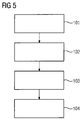
- Fig. 5 shows a block diagram of a method for relative position detection of the stations 1, 2 by means of radio location.
- the first station 1 transmits a locating signal 15 via the first antenna 11
- second station 2 receives the locating signal 15 via the base-station modulated antennas 21-24 as modulated reflected locating signals 16.
- the first station 1 receives the modulated reflected locating signals 16 via the antenna 11.
- the phase-modulated signals of the received modulated reflected locating signals 16 are obtained at least one position angle ⁇ , ⁇ determined for the relative position between the first station 1 and the second station 2.
- the proposed method and the proposed arrangement for the relative position detection of stations by means of radio location make it possible to query a whole series of base-modulated antennas and evaluate the phase relationships between the base-modulated antennas, for example, to perform an angle measurement.
- the phase relationships of the response signals generated by them that is to say of the modulated reflected position signals, also follow a linear relationship and thus to the angle of the second station relative to the readout unit, ie to the first Lock station back.
- the different modulated reflected received signals of a given footpoint-modulated antenna also differ and thus allow conclusions about the angle of the readout units or the first stations to the given fußyakmodul elected antenna of the respective second station.
- a further advantageous feature of the proposed arrangement having a plurality of read-out units or first stations and a plurality of base station-modulated antennas of a second station is the potential increase in range and robustness by means of suitable billing of the signals. This In particular, this is made possible by the knowledge of the transit time phases, which makes it possible, for example, to apply certain methods of digital beam control. As a result, multipath effects, for example, can be hidden, so that the measurement accuracy can be increased.
- an in-phase superimposition of the total n * m individual signals can increase the signal-to-noise ratio, which can significantly expand the range of corresponding systems.
- the proposed method and the proposed arrangement enable strongly asymmetric systems, which concentrate a large part of the functionality with regard to hardware and algorithmics in the read-out part, ie in the first station.
- the second station which includes the base-station modulated antennas, on the other hand, can be constructed very simply and inexpensively, for example using RFID tags. This makes the proposed system concept applicable to a variety of applications.
Landscapes
- Engineering & Computer Science (AREA)
- Radar, Positioning & Navigation (AREA)
- Remote Sensing (AREA)
- Physics & Mathematics (AREA)
- General Physics & Mathematics (AREA)
- Computer Networks & Wireless Communication (AREA)
- Position Fixing By Use Of Radio Waves (AREA)
- Radar Systems Or Details Thereof (AREA)
- Investigating, Analyzing Materials By Fluorescence Or Luminescence (AREA)
Claims (13)
- Procédé de détermination de la position relative de stations (1, 2) au moyen d'une localisation radio, dans lequel au moins une première station (1) présente au moins une première antenne (11) et au moins une deuxième station (2) présente au moins deux antennes modulées à la base (21, 22, 23, 24), dans lequel
la première station (1) envoie (101) au moins un signal de localisation (15) par l'intermédiaire de la première antenne (11) ;
la deuxième station (2) réfléchit (102) de manière modulée le signal de localisation (15) par l'intermédiaire d'une première antenne modulée à la base (21) en tant que premier signal de localisation (16) modulé réfléchi et par l'intermédiaire d'une deuxième antenne modulée à la base (22) en tant que deuxième signal de localisation (16) modulé réfléchi ;
la première station (1) reçoit (103) les signaux de localisation (16) modulés réfléchis par l'intermédiaire de l'antenne (11) ; et
au moins un angle de position (α, β) pour la position relative entre la première station (1) et la deuxième station (2) est déterminé (104) à partir des rapports de phase des signaux de localisation (16) modulés réfléchis reçus. - Procédé selon la revendication 1,
caractérisé en ce que,
les antennes modulées à la base (21, 22, 23, 24) reflètent différentes modulations (fmod1, fmod2, fmod3, fmod4) du signal de localisation (15). - Procédé selon la revendication 1 ou 2,
dans lequel la première station (1) présente une deuxième antenne (11), et dans lequel la première station (1) envoie le signal de localisation (15) par l'intermédiaire de la première antenne et par l'intermédiaire de la deuxième antenne (11) avec des fréquences différentes ou avec des modulations différentes, en particulier avec des signaux orthogonaux. - Procédé selon l'une quelconque des revendications 1 à 3,
caractérisé en ce que,
la deuxième station (2) est conçue en tant que module Backscatter destiné à une rétrodiffusion modulée du signal de localisation (15). - Procédé selon la revendication 4,
caractérisé en ce que,
la deuxième station (2) est conçue en tant que transpondeur RFID passif. - Procédé selon l'une quelconque des revendications 1 à 5,
caractérisé en ce que,
les antennes modulées à la base (21, 22, 23, 24) de la au moins une deuxième station (2) sont agencées sur une ligne avec un intervalle constant. - Procédé selon l'une quelconque des revendications 1 à 6,
caractérisé en ce que,
les antennes (11) de la au moins une première station (1) sont agencées sur une ligne avec un intervalle constant. - Procédé selon l'une quelconque des revendications 1 à 7,
caractérisé en ce que,
un signal radar à émission continue est utilisé en tant que signal de localisation (15). - Procédé selon l'une quelconque des revendications 1 à 7,
caractérisé en ce que,
une rampe de fréquence est utilisée en tant que signal de localisation (15). - Procédé selon l'une quelconque des revendications 1 à 9,
caractérisé en ce que,
les signaux de localisation (16) réfléchis modulés reçus par la au moins une première station (1) ainsi que les signaux de localisation (16) modulés réfléchis envoyés par la au moins une deuxième station (2) sont cohérents, le au moins un angle de position (α, β) étant calculé à partir des rapports de phase des signaux de localisation (16) modulés réfléchis envoyés et des signaux de localisation (16) modulés réfléchis reçus. - Procédé selon l'une quelconque des revendications 1 à 10,
caractérisé en ce que,
la au moins une première station (1) émet un signal de synchronisation séparé destiné à une synchronisation de la au moins une première station (1) avec la au moins une deuxième station (2). - Procédé selon l'une quelconque des revendications 1 à 11,
caractérisé en ce que,
des retards de signal des signaux de localisation sont utilisés pour une mesure d'intervalle entre les stations (1, 2). - Agencement pour une détermination de la position relative de stations (1, 2) au moyen d'une localisation radio, dans lequel au moins une première station (1) présente au moins une première antenne (11) et au moins une deuxième station (2) présente au moins deux antennes modulées à la base (21, 22, 23, 24), dans lequel
la première station (1) est conçue pour émettre (101) au moins un signal de localisation (15) par l'intermédiaire de la première antenne (11) ;
la deuxième station (2) est conçue pour réfléchir (102) de manière modulée le signal de localisation (15) par l'intermédiaire de la première antenne modulée à la base (21) en tant que premier signal de localisation (16) modulé réfléchi et par l'intermédiaire de la deuxième antenne modulée à la base (22) en tant que deuxième signal de localisation (16) modulé réfléchi ;
la première station (101) est en outre conçue pour recevoir (103), par l'intermédiaire de l'antenne (11), les signaux de localisation (16) modulés réfléchis et pour déterminer (104) au moins un angle de position (α, β) pour la position relative entre la première station (1) et la deuxième station (2) à partir des rapports de phase des signaux de localisation (16) modulés réfléchis.
Applications Claiming Priority (2)
| Application Number | Priority Date | Filing Date | Title |
|---|---|---|---|
| DE102012211809.8A DE102012211809A1 (de) | 2012-07-06 | 2012-07-06 | Verfahren und Anordnung zur relativen Lageerkennung von Stationen mittels Funkortung |
| PCT/EP2013/063879 WO2014006013A1 (fr) | 2012-07-06 | 2013-07-02 | Procédé et ensemble pour la détection relative de position de stations par radiolocalisation |
Publications (2)
| Publication Number | Publication Date |
|---|---|
| EP2845026A1 EP2845026A1 (fr) | 2015-03-11 |
| EP2845026B1 true EP2845026B1 (fr) | 2016-06-15 |
Family
ID=48746497
Family Applications (1)
| Application Number | Title | Priority Date | Filing Date |
|---|---|---|---|
| EP13734047.7A Not-in-force EP2845026B1 (fr) | 2012-07-06 | 2013-07-02 | Procédé et ensemble pour la détection relative de position de stations par radiolocalisation |
Country Status (7)
| Country | Link |
|---|---|
| US (1) | US10006992B2 (fr) |
| EP (1) | EP2845026B1 (fr) |
| CN (1) | CN104428685B (fr) |
| CA (1) | CA2877437A1 (fr) |
| DE (1) | DE102012211809A1 (fr) |
| ES (1) | ES2591130T3 (fr) |
| WO (1) | WO2014006013A1 (fr) |
Cited By (1)
| Publication number | Priority date | Publication date | Assignee | Title |
|---|---|---|---|---|
| DE102019120016A1 (de) * | 2019-07-24 | 2021-01-28 | Ifm Electronic Gmbh | Verfahren zum Betreiben einer automatischen Ladestation für ein Elektrofahrzeug mit einer RFID-Basis. |
Families Citing this family (16)
| Publication number | Priority date | Publication date | Assignee | Title |
|---|---|---|---|---|
| DE102014220513A1 (de) * | 2014-09-30 | 2016-04-14 | Siemens Aktiengesellschaft | Mehrkanal-Radarverfahren und Mehrkanal-Radarsystem |
| US10079616B2 (en) | 2014-12-19 | 2018-09-18 | University Of Washington | Devices and methods for backscatter communication using one or more wireless communication protocols including bluetooth low energy examples |
| US10873363B2 (en) | 2015-08-12 | 2020-12-22 | University Of Washington | Backscatter devices and network systems incorporating backscatter devices |
| EP3408681B1 (fr) * | 2016-01-26 | 2024-01-24 | University of Washington | Dispositifs de rétrodiffusion comprenant des exemples de fonctionnement à bande latérale unique |
| EP3440454A4 (fr) | 2016-04-04 | 2019-12-18 | The University of Washington | Dispositifs et systèmes de rétrodiffusion fournissant des signaux rétrodiffusés comportant des paquets ofdm |
| DE102016207424A1 (de) * | 2016-04-29 | 2017-11-02 | Siemens Aktiengesellschaft | Transponder, insbesondere RFID Transponder, und Verfahren zum Betreiben eines, insbesondere RFID, Transponders |
| EP3529902B1 (fr) | 2016-10-18 | 2021-06-09 | University of Washington | Systèmes, dispositifs et techniques de rétrodiffusion utilisant une modulation css et/ou une suppression d'harmoniques d'ordre supérieur |
| DE102017102117A1 (de) * | 2017-02-03 | 2018-08-09 | Jungheinrich Aktiengesellschaft | Verfahren und System zur Positionsbestimmung von mindestens einem Flurförderzeug |
| DE102017107212A1 (de) * | 2017-04-04 | 2018-10-04 | Infineon Technologies Ag | Verfahren und Vorrichtung zum Verarbeiten von Radarsignalen |
| US11212479B2 (en) | 2017-04-06 | 2021-12-28 | University Of Washington | Image and/or video transmission using backscatter devices |
| FR3077141B1 (fr) * | 2018-01-22 | 2020-07-03 | Kerlink | Procede de geolocalisation d'un dispositif emetteur de signal |
| CN109143250B (zh) * | 2018-07-09 | 2023-04-07 | 上海肖可雷电子科技有限公司 | 一种基于激光定位的系统与方法 |
| DE102020102155A1 (de) * | 2020-01-29 | 2021-07-29 | Sick Ag | Sicherheitssystem und Verfahren zur Lokalisierung |
| DE102020202390A1 (de) | 2020-02-25 | 2021-08-26 | Rheinisch-Westfälische Technische Hochschule (Rwth) Aachen | System zur Bestimmung der räumlichen Position eines ersten Objektes relativ zu einem zweiten Objekt |
| CN113115437B (zh) * | 2021-03-10 | 2023-02-03 | 成都永奉科技有限公司 | 定位标签与基站前后位置关系判定方法及系统 |
| US12111383B2 (en) * | 2021-12-23 | 2024-10-08 | Gm Cruise Holdings Llc | Radar signaling for emergency scenarios |
Family Cites Families (15)
| Publication number | Priority date | Publication date | Assignee | Title |
|---|---|---|---|---|
| US4075632A (en) * | 1974-08-27 | 1978-02-21 | The United States Of America As Represented By The United States Department Of Energy | Interrogation, and detection system |
| NL9002683A (nl) * | 1990-12-06 | 1992-07-01 | Nedap Nv | Retro-reflectieve microgolf transponder. |
| DE4213879A1 (de) * | 1992-04-28 | 1993-11-04 | Bosch Gmbh Robert | Kommunikationssystem zur datenuebertragung von einem bewegten fahrzeug auf eine ortsfeste bake |
| US6236315B1 (en) * | 1999-10-19 | 2001-05-22 | Lucent Technologies Inc. | Method and apparatus for improving the interrogation range of an RF tag |
| US7170412B2 (en) * | 2004-08-31 | 2007-01-30 | Symbol Technologies, Inc. | Angle of position object location system and method |
| DE102006037247A1 (de) * | 2006-08-09 | 2008-02-14 | Siemens Ag | Vorrichtung und Verfahren zur Ortung eines Zielobjektes |
| US7880618B2 (en) * | 2007-03-28 | 2011-02-01 | Round Rock Research, Llc | Methods and systems of determining physical characteristics associated with objects tagged with RFID tags |
| US20090002165A1 (en) | 2007-06-28 | 2009-01-01 | Micron Technology, Inc. | Method and system of determining a location characteristic of a rfid tag |
| US20090289873A1 (en) * | 2007-12-19 | 2009-11-26 | Robert Schilling | Object direction indication through the use of multiple antenna beams |
| DE102008035440B4 (de) * | 2008-07-25 | 2010-12-09 | Fraunhofer-Gesellschaft zur Förderung der angewandten Forschung e.V. | Vorrichtung und Verfahren zum Bestimmen der Entfernung und/oder Orientierung eines beweglichen Objekts |
| US8797213B2 (en) | 2009-09-30 | 2014-08-05 | Broadcom Corporation | Methods and systems for estimating angle of arrival |
| DE102009049978A1 (de) * | 2009-10-20 | 2011-05-05 | Siemens Aktiengesellschaft | Verfahren und Vorrichtung zur relativen Lageerkennung von Funkortungsstationen |
| TWI488123B (zh) * | 2009-12-29 | 2015-06-11 | Univ Nat Taiwan Science Tech | 射頻電子標籤、射頻傳輸方法以及射頻辨識系統 |
| US20130119135A1 (en) * | 2010-07-26 | 2013-05-16 | Polyvalor, Limited Partnership | Bi-directional and multi-frequency rf signaling system |
| US9612321B2 (en) * | 2011-10-07 | 2017-04-04 | Siemens Aktiengesellschaft | Method for angle determination for moving assemblies, and apparatus |
-
2012
- 2012-07-06 DE DE102012211809.8A patent/DE102012211809A1/de not_active Withdrawn
-
2013
- 2013-07-02 CA CA2877437A patent/CA2877437A1/fr not_active Withdrawn
- 2013-07-02 WO PCT/EP2013/063879 patent/WO2014006013A1/fr not_active Ceased
- 2013-07-02 US US14/413,060 patent/US10006992B2/en active Active
- 2013-07-02 EP EP13734047.7A patent/EP2845026B1/fr not_active Not-in-force
- 2013-07-02 CN CN201380035987.4A patent/CN104428685B/zh not_active Expired - Fee Related
- 2013-07-02 ES ES13734047.7T patent/ES2591130T3/es active Active
Cited By (2)
| Publication number | Priority date | Publication date | Assignee | Title |
|---|---|---|---|---|
| DE102019120016A1 (de) * | 2019-07-24 | 2021-01-28 | Ifm Electronic Gmbh | Verfahren zum Betreiben einer automatischen Ladestation für ein Elektrofahrzeug mit einer RFID-Basis. |
| DE102019120016B4 (de) * | 2019-07-24 | 2021-04-22 | Ifm Electronic Gmbh | Verfahren zum Betreiben einer automatischen Ladestation für ein Elektrofahrzeug mit einer RFID-Basis. |
Also Published As
| Publication number | Publication date |
|---|---|
| DE102012211809A1 (de) | 2014-01-09 |
| EP2845026A1 (fr) | 2015-03-11 |
| CN104428685A (zh) | 2015-03-18 |
| US20150168535A1 (en) | 2015-06-18 |
| CN104428685B (zh) | 2016-06-15 |
| WO2014006013A1 (fr) | 2014-01-09 |
| US10006992B2 (en) | 2018-06-26 |
| ES2591130T3 (es) | 2016-11-25 |
| CA2877437A1 (fr) | 2014-01-09 |
Similar Documents
| Publication | Publication Date | Title |
|---|---|---|
| EP2845026B1 (fr) | Procédé et ensemble pour la détection relative de position de stations par radiolocalisation | |
| EP3588134B1 (fr) | Procédé dans un système radar, système radar ou dispositif d'un système radar | |
| DE69020203T2 (de) | Verfahren und Gerät zur Hilfe des Landfahrzeugverkehrs. | |
| EP3004918B1 (fr) | Suppression d'interférences dans un radar fmcw | |
| DE68920684T2 (de) | System zur Diskrimination von Signalen. | |
| DE69522499T2 (de) | Einrichtung zur berührungslosen Messung der Geschwindigkeit eines Eisenbahnfahrzeuges | |
| DE102006004023A1 (de) | Vorrichtung und Verfahren zur mehrdimensionalen Ortung von Zielobjekten, insbesondere RFID-Transpondern | |
| DE102012103085B4 (de) | Radarvorrichtung | |
| WO2003040753A1 (fr) | Systeme transpondeur et procede de telemetrie | |
| DE112017002559T5 (de) | Geschwindigkeitserfassungsvorrichtung | |
| DE69731723T2 (de) | Mikrowellen flugzeug landesystem | |
| DE2715383B2 (de) | Funknavigationsanlage | |
| DE102005009579B4 (de) | Verfahren zur Lokalisierung eines Detektierplättchens | |
| WO2011047899A1 (fr) | Procédé et dispositif de détection de position relative de stations par radiolocalisation | |
| DE102006037247A1 (de) | Vorrichtung und Verfahren zur Ortung eines Zielobjektes | |
| WO2008049565A1 (fr) | Concept pour la détermination de position d'un transpondeur passif dans un système radio | |
| EP4066006A1 (fr) | Identification et localisation simultanées d'objets au moyen d'une mesure bistatique | |
| DE102016119484B4 (de) | Positionsermittlungseinrichtung | |
| DE102019201742A1 (de) | Transceiver und Verfahren zur Distanzmessung | |
| GB2268350A (en) | High range resolution radar | |
| WO2008071457A1 (fr) | Procédé et système de détermination d'une position | |
| DE69313790T2 (de) | Funkortungs-Verfahren und Management-System für eine Flotte von Fahrzeugen | |
| DE102017214889A1 (de) | Distanzmessung in Funkidentifikationssystemen | |
| EP2096461A1 (fr) | Dispositif de mesure et procédé de mesure destinés à la détermination d'un intervalle, d'une vitesse, d'une accélération, d'un mouvement brusque, d'un angle d'entrée, d'une vitesse d'angle d'entrée, d'une accélération d'angle d'entrée et/ou d'un mouvement brusque d'angle d'entrée entre un dispositif d'émission et de réception et un objet | |
| DE102018207242A1 (de) | Verfahren zum Ermitteln einer Position und/oder räumlichen Lage eines Werkzeugs, Verfahren zum Ausgeben zumindest eines Lageidentifizierungssignals im Millimeterwellenfrequenzbereich und Verfahren zur Positionsbestimmung eines Werkzeugs |
Legal Events
| Date | Code | Title | Description |
|---|---|---|---|
| PUAI | Public reference made under article 153(3) epc to a published international application that has entered the european phase |
Free format text: ORIGINAL CODE: 0009012 |
|
| 17P | Request for examination filed |
Effective date: 20141205 |
|
| AK | Designated contracting states |
Kind code of ref document: A1 Designated state(s): AL AT BE BG CH CY CZ DE DK EE ES FI FR GB GR HR HU IE IS IT LI LT LU LV MC MK MT NL NO PL PT RO RS SE SI SK SM TR |
|
| AX | Request for extension of the european patent |
Extension state: BA ME |
|
| DAX | Request for extension of the european patent (deleted) | ||
| RIC1 | Information provided on ipc code assigned before grant |
Ipc: G01S 5/02 20100101ALI20151125BHEP Ipc: G01S 13/75 20060101ALI20151125BHEP Ipc: G01S 13/82 20060101ALI20151125BHEP Ipc: G01S 13/02 20060101ALI20151125BHEP Ipc: G01S 3/48 20060101AFI20151125BHEP |
|
| GRAP | Despatch of communication of intention to grant a patent |
Free format text: ORIGINAL CODE: EPIDOSNIGR1 |
|
| INTG | Intention to grant announced |
Effective date: 20160112 |
|
| GRAS | Grant fee paid |
Free format text: ORIGINAL CODE: EPIDOSNIGR3 |
|
| GRAA | (expected) grant |
Free format text: ORIGINAL CODE: 0009210 |
|
| AK | Designated contracting states |
Kind code of ref document: B1 Designated state(s): AL AT BE BG CH CY CZ DE DK EE ES FI FR GB GR HR HU IE IS IT LI LT LU LV MC MK MT NL NO PL PT RO RS SE SI SK SM TR |
|
| REG | Reference to a national code |
Ref country code: CH Ref legal event code: EP Ref country code: GB Ref legal event code: FG4D Free format text: NOT ENGLISH |
|
| REG | Reference to a national code |
Ref country code: IE Ref legal event code: FG4D Free format text: LANGUAGE OF EP DOCUMENT: GERMAN |
|
| REG | Reference to a national code |
Ref country code: AT Ref legal event code: REF Ref document number: 806768 Country of ref document: AT Kind code of ref document: T Effective date: 20160715 |
|
| REG | Reference to a national code |
Ref country code: FR Ref legal event code: PLFP Year of fee payment: 4 |
|
| REG | Reference to a national code |
Ref country code: DE Ref legal event code: R096 Ref document number: 502013003419 Country of ref document: DE |
|
| REG | Reference to a national code |
Ref country code: LT Ref legal event code: MG4D |
|
| REG | Reference to a national code |
Ref country code: NL Ref legal event code: MP Effective date: 20160615 |
|
| PG25 | Lapsed in a contracting state [announced via postgrant information from national office to epo] |
Ref country code: FI Free format text: LAPSE BECAUSE OF FAILURE TO SUBMIT A TRANSLATION OF THE DESCRIPTION OR TO PAY THE FEE WITHIN THE PRESCRIBED TIME-LIMIT Effective date: 20160615 Ref country code: NO Free format text: LAPSE BECAUSE OF FAILURE TO SUBMIT A TRANSLATION OF THE DESCRIPTION OR TO PAY THE FEE WITHIN THE PRESCRIBED TIME-LIMIT Effective date: 20160915 Ref country code: LT Free format text: LAPSE BECAUSE OF FAILURE TO SUBMIT A TRANSLATION OF THE DESCRIPTION OR TO PAY THE FEE WITHIN THE PRESCRIBED TIME-LIMIT Effective date: 20160615 |
|
| REG | Reference to a national code |
Ref country code: ES Ref legal event code: FG2A Ref document number: 2591130 Country of ref document: ES Kind code of ref document: T3 Effective date: 20161125 |
|
| PG25 | Lapsed in a contracting state [announced via postgrant information from national office to epo] |
Ref country code: GR Free format text: LAPSE BECAUSE OF FAILURE TO SUBMIT A TRANSLATION OF THE DESCRIPTION OR TO PAY THE FEE WITHIN THE PRESCRIBED TIME-LIMIT Effective date: 20160916 Ref country code: HR Free format text: LAPSE BECAUSE OF FAILURE TO SUBMIT A TRANSLATION OF THE DESCRIPTION OR TO PAY THE FEE WITHIN THE PRESCRIBED TIME-LIMIT Effective date: 20160615 Ref country code: RS Free format text: LAPSE BECAUSE OF FAILURE TO SUBMIT A TRANSLATION OF THE DESCRIPTION OR TO PAY THE FEE WITHIN THE PRESCRIBED TIME-LIMIT Effective date: 20160615 Ref country code: LV Free format text: LAPSE BECAUSE OF FAILURE TO SUBMIT A TRANSLATION OF THE DESCRIPTION OR TO PAY THE FEE WITHIN THE PRESCRIBED TIME-LIMIT Effective date: 20160615 Ref country code: SE Free format text: LAPSE BECAUSE OF FAILURE TO SUBMIT A TRANSLATION OF THE DESCRIPTION OR TO PAY THE FEE WITHIN THE PRESCRIBED TIME-LIMIT Effective date: 20160615 Ref country code: NL Free format text: LAPSE BECAUSE OF FAILURE TO SUBMIT A TRANSLATION OF THE DESCRIPTION OR TO PAY THE FEE WITHIN THE PRESCRIBED TIME-LIMIT Effective date: 20160615 |
|
| PG25 | Lapsed in a contracting state [announced via postgrant information from national office to epo] |
Ref country code: BE Free format text: LAPSE BECAUSE OF NON-PAYMENT OF DUE FEES Effective date: 20160731 |
|
| PG25 | Lapsed in a contracting state [announced via postgrant information from national office to epo] |
Ref country code: EE Free format text: LAPSE BECAUSE OF FAILURE TO SUBMIT A TRANSLATION OF THE DESCRIPTION OR TO PAY THE FEE WITHIN THE PRESCRIBED TIME-LIMIT Effective date: 20160615 Ref country code: CZ Free format text: LAPSE BECAUSE OF FAILURE TO SUBMIT A TRANSLATION OF THE DESCRIPTION OR TO PAY THE FEE WITHIN THE PRESCRIBED TIME-LIMIT Effective date: 20160615 Ref country code: RO Free format text: LAPSE BECAUSE OF FAILURE TO SUBMIT A TRANSLATION OF THE DESCRIPTION OR TO PAY THE FEE WITHIN THE PRESCRIBED TIME-LIMIT Effective date: 20160615 Ref country code: SK Free format text: LAPSE BECAUSE OF FAILURE TO SUBMIT A TRANSLATION OF THE DESCRIPTION OR TO PAY THE FEE WITHIN THE PRESCRIBED TIME-LIMIT Effective date: 20160615 Ref country code: IS Free format text: LAPSE BECAUSE OF FAILURE TO SUBMIT A TRANSLATION OF THE DESCRIPTION OR TO PAY THE FEE WITHIN THE PRESCRIBED TIME-LIMIT Effective date: 20161015 |
|
| PG25 | Lapsed in a contracting state [announced via postgrant information from national office to epo] |
Ref country code: PT Free format text: LAPSE BECAUSE OF FAILURE TO SUBMIT A TRANSLATION OF THE DESCRIPTION OR TO PAY THE FEE WITHIN THE PRESCRIBED TIME-LIMIT Effective date: 20161017 Ref country code: PL Free format text: LAPSE BECAUSE OF FAILURE TO SUBMIT A TRANSLATION OF THE DESCRIPTION OR TO PAY THE FEE WITHIN THE PRESCRIBED TIME-LIMIT Effective date: 20160615 Ref country code: SM Free format text: LAPSE BECAUSE OF FAILURE TO SUBMIT A TRANSLATION OF THE DESCRIPTION OR TO PAY THE FEE WITHIN THE PRESCRIBED TIME-LIMIT Effective date: 20160615 |
|
| REG | Reference to a national code |
Ref country code: CH Ref legal event code: PL |
|
| REG | Reference to a national code |
Ref country code: DE Ref legal event code: R097 Ref document number: 502013003419 Country of ref document: DE |
|
| PG25 | Lapsed in a contracting state [announced via postgrant information from national office to epo] |
Ref country code: MC Free format text: LAPSE BECAUSE OF FAILURE TO SUBMIT A TRANSLATION OF THE DESCRIPTION OR TO PAY THE FEE WITHIN THE PRESCRIBED TIME-LIMIT Effective date: 20160615 |
|
| PLBE | No opposition filed within time limit |
Free format text: ORIGINAL CODE: 0009261 |
|
| STAA | Information on the status of an ep patent application or granted ep patent |
Free format text: STATUS: NO OPPOSITION FILED WITHIN TIME LIMIT |
|
| PG25 | Lapsed in a contracting state [announced via postgrant information from national office to epo] |
Ref country code: LI Free format text: LAPSE BECAUSE OF NON-PAYMENT OF DUE FEES Effective date: 20160731 Ref country code: CH Free format text: LAPSE BECAUSE OF NON-PAYMENT OF DUE FEES Effective date: 20160731 |
|
| REG | Reference to a national code |
Ref country code: IE Ref legal event code: MM4A |
|
| 26N | No opposition filed |
Effective date: 20170316 |
|
| PG25 | Lapsed in a contracting state [announced via postgrant information from national office to epo] |
Ref country code: DK Free format text: LAPSE BECAUSE OF FAILURE TO SUBMIT A TRANSLATION OF THE DESCRIPTION OR TO PAY THE FEE WITHIN THE PRESCRIBED TIME-LIMIT Effective date: 20160615 |
|
| REG | Reference to a national code |
Ref country code: FR Ref legal event code: PLFP Year of fee payment: 5 |
|
| PG25 | Lapsed in a contracting state [announced via postgrant information from national office to epo] |
Ref country code: IE Free format text: LAPSE BECAUSE OF NON-PAYMENT OF DUE FEES Effective date: 20160702 |
|
| PG25 | Lapsed in a contracting state [announced via postgrant information from national office to epo] |
Ref country code: LU Free format text: LAPSE BECAUSE OF NON-PAYMENT OF DUE FEES Effective date: 20160702 Ref country code: SI Free format text: LAPSE BECAUSE OF FAILURE TO SUBMIT A TRANSLATION OF THE DESCRIPTION OR TO PAY THE FEE WITHIN THE PRESCRIBED TIME-LIMIT Effective date: 20160615 |
|
| PG25 | Lapsed in a contracting state [announced via postgrant information from national office to epo] |
Ref country code: HU Free format text: LAPSE BECAUSE OF FAILURE TO SUBMIT A TRANSLATION OF THE DESCRIPTION OR TO PAY THE FEE WITHIN THE PRESCRIBED TIME-LIMIT; INVALID AB INITIO Effective date: 20130702 |
|
| PG25 | Lapsed in a contracting state [announced via postgrant information from national office to epo] |
Ref country code: MT Free format text: LAPSE BECAUSE OF FAILURE TO SUBMIT A TRANSLATION OF THE DESCRIPTION OR TO PAY THE FEE WITHIN THE PRESCRIBED TIME-LIMIT Effective date: 20160615 Ref country code: MK Free format text: LAPSE BECAUSE OF FAILURE TO SUBMIT A TRANSLATION OF THE DESCRIPTION OR TO PAY THE FEE WITHIN THE PRESCRIBED TIME-LIMIT Effective date: 20160615 Ref country code: CY Free format text: LAPSE BECAUSE OF FAILURE TO SUBMIT A TRANSLATION OF THE DESCRIPTION OR TO PAY THE FEE WITHIN THE PRESCRIBED TIME-LIMIT Effective date: 20160615 |
|
| REG | Reference to a national code |
Ref country code: FR Ref legal event code: PLFP Year of fee payment: 6 |
|
| PG25 | Lapsed in a contracting state [announced via postgrant information from national office to epo] |
Ref country code: BG Free format text: LAPSE BECAUSE OF FAILURE TO SUBMIT A TRANSLATION OF THE DESCRIPTION OR TO PAY THE FEE WITHIN THE PRESCRIBED TIME-LIMIT Effective date: 20160615 |
|
| PG25 | Lapsed in a contracting state [announced via postgrant information from national office to epo] |
Ref country code: AL Free format text: LAPSE BECAUSE OF FAILURE TO SUBMIT A TRANSLATION OF THE DESCRIPTION OR TO PAY THE FEE WITHIN THE PRESCRIBED TIME-LIMIT Effective date: 20160615 Ref country code: TR Free format text: LAPSE BECAUSE OF FAILURE TO SUBMIT A TRANSLATION OF THE DESCRIPTION OR TO PAY THE FEE WITHIN THE PRESCRIBED TIME-LIMIT Effective date: 20160615 |
|
| REG | Reference to a national code |
Ref country code: AT Ref legal event code: MM01 Ref document number: 806768 Country of ref document: AT Kind code of ref document: T Effective date: 20180702 |
|
| PG25 | Lapsed in a contracting state [announced via postgrant information from national office to epo] |
Ref country code: AT Free format text: LAPSE BECAUSE OF NON-PAYMENT OF DUE FEES Effective date: 20180702 |
|
| PGFP | Annual fee paid to national office [announced via postgrant information from national office to epo] |
Ref country code: IT Payment date: 20230725 Year of fee payment: 11 Ref country code: GB Payment date: 20230807 Year of fee payment: 11 |
|
| PGFP | Annual fee paid to national office [announced via postgrant information from national office to epo] |
Ref country code: FR Payment date: 20230720 Year of fee payment: 11 Ref country code: DE Payment date: 20230918 Year of fee payment: 11 |
|
| PGFP | Annual fee paid to national office [announced via postgrant information from national office to epo] |
Ref country code: ES Payment date: 20231027 Year of fee payment: 11 |
|
| REG | Reference to a national code |
Ref country code: DE Ref legal event code: R119 Ref document number: 502013003419 Country of ref document: DE |
|
| GBPC | Gb: european patent ceased through non-payment of renewal fee |
Effective date: 20240702 |
|
| PG25 | Lapsed in a contracting state [announced via postgrant information from national office to epo] |
Ref country code: DE Free format text: LAPSE BECAUSE OF NON-PAYMENT OF DUE FEES Effective date: 20250201 |
|
| PG25 | Lapsed in a contracting state [announced via postgrant information from national office to epo] |
Ref country code: FR Free format text: LAPSE BECAUSE OF NON-PAYMENT OF DUE FEES Effective date: 20240731 |
|
| PG25 | Lapsed in a contracting state [announced via postgrant information from national office to epo] |
Ref country code: GB Free format text: LAPSE BECAUSE OF NON-PAYMENT OF DUE FEES Effective date: 20240702 |
|
| PG25 | Lapsed in a contracting state [announced via postgrant information from national office to epo] |
Ref country code: IT Free format text: LAPSE BECAUSE OF NON-PAYMENT OF DUE FEES Effective date: 20240702 |
|
| REG | Reference to a national code |
Ref country code: ES Ref legal event code: FD2A Effective date: 20250827 |
|
| PG25 | Lapsed in a contracting state [announced via postgrant information from national office to epo] |
Ref country code: ES Free format text: LAPSE BECAUSE OF NON-PAYMENT OF DUE FEES Effective date: 20240703 |