EP2845497A1 - Verbesserte Wasserpfeife - Google Patents
Verbesserte Wasserpfeife Download PDFInfo
- Publication number
- EP2845497A1 EP2845497A1 EP14250100.6A EP14250100A EP2845497A1 EP 2845497 A1 EP2845497 A1 EP 2845497A1 EP 14250100 A EP14250100 A EP 14250100A EP 2845497 A1 EP2845497 A1 EP 2845497A1
- Authority
- EP
- European Patent Office
- Prior art keywords
- shisha
- shisha head
- head according
- vapourizer
- head
- Prior art date
- Legal status (The legal status is an assumption and is not a legal conclusion. Google has not performed a legal analysis and makes no representation as to the accuracy of the status listed.)
- Withdrawn
Links
Images






Classifications
-
- A—HUMAN NECESSITIES
- A24—TOBACCO; CIGARS; CIGARETTES; SIMULATED SMOKING DEVICES; SMOKERS' REQUISITES
- A24F—SMOKERS' REQUISITES; MATCH BOXES; SIMULATED SMOKING DEVICES
- A24F1/00—Tobacco pipes
- A24F1/30—Hookahs
-
- A—HUMAN NECESSITIES
- A24—TOBACCO; CIGARS; CIGARETTES; SIMULATED SMOKING DEVICES; SMOKERS' REQUISITES
- A24D—CIGARS; CIGARETTES; TOBACCO SMOKE FILTERS; MOUTHPIECES OF CIGARS OR CIGARETTES; MANUFACTURE OF TOBACCO SMOKE FILTERS OR MOUTHPIECES
- A24D1/00—Cigars; Cigarettes
- A24D1/14—Tobacco cartridges for pipes
-
- A—HUMAN NECESSITIES
- A24—TOBACCO; CIGARS; CIGARETTES; SIMULATED SMOKING DEVICES; SMOKERS' REQUISITES
- A24F—SMOKERS' REQUISITES; MATCH BOXES; SIMULATED SMOKING DEVICES
- A24F40/00—Electrically operated smoking devices; Component parts thereof; Manufacture thereof; Maintenance or testing thereof; Charging means specially adapted therefor
- A24F40/30—Devices using two or more structurally separated inhalable precursors, e.g. using two liquid precursors in two cartridges
-
- A—HUMAN NECESSITIES
- A24—TOBACCO; CIGARS; CIGARETTES; SIMULATED SMOKING DEVICES; SMOKERS' REQUISITES
- A24F—SMOKERS' REQUISITES; MATCH BOXES; SIMULATED SMOKING DEVICES
- A24F40/00—Electrically operated smoking devices; Component parts thereof; Manufacture thereof; Maintenance or testing thereof; Charging means specially adapted therefor
- A24F40/40—Constructional details, e.g. connection of cartridges and battery parts
-
- A—HUMAN NECESSITIES
- A24—TOBACCO; CIGARS; CIGARETTES; SIMULATED SMOKING DEVICES; SMOKERS' REQUISITES
- A24F—SMOKERS' REQUISITES; MATCH BOXES; SIMULATED SMOKING DEVICES
- A24F40/00—Electrically operated smoking devices; Component parts thereof; Manufacture thereof; Maintenance or testing thereof; Charging means specially adapted therefor
- A24F40/10—Devices using liquid inhalable precursors
Definitions
- This invention relates to an improved shisha, and in particular to an improved shisha head.
- the shisha 100 comprises a bowl 102 containing tobacco 103 beneath a screen 104 of perforated aluminium foil, metal or glass.
- the top of the bowl 102 may be closed by a windscreen or cover.
- the bowl 102 is mounted on top of a hollow body 106 containing a chamber 107 partially filled with water 108.
- the bottom of the bowl 102 is connected to a first hollow tube 109 which extends into the body 106 and has a lower end 109a opening beneath the surface of the water 108.
- a user mouthpiece 110 is connected through a second hollow tube 111, which is generally flexible, to the air space 112 within the hollow body 106 above the surface of the water 108.
- lit coals 113 are placed on top of the screen 104 to heat the tobacco 103 and generate smoke.
- a user sucks on the mouthpiece 110, producing a partial vacuum within the chamber 107, smoke is pulled from within the bowl 102 down the first tube 109, and bubbles through the water 108 into the air space 112 within the chamber 107. The smoke is then sucked along the second tube 111 to the mouthpiece 110 and can be inhaled by the user.
- the problem addressed by the present invention is how to provide an improved shisha which is less likely to have negative health effects and will not be affected by legislation controlling or limiting smoking.
- the present invention was made in order to solve these problems, at least in part.
- a first aspect of the invention provides a shisha head comprising an air inlet, an air outlet suitable for connection to a shisha, at least one vapourizer and an air flow sensor arranged to detect air flow through the shisha head, wherein the vapourizer is arranged to produce vapour in response to the air flow sensor detecting a flow of air through the shisha head.
- the vapourizer contains e-liquid.
- the vapourizer is arranged to produce a vapour mixture of e-liquid that contains nicotine.
- the vapourizer contains a liquid solution of nicotine.
- the vapourizer is arranged to produce a mixture of vapour and at least one flavouring substance.
- the vapourizer contains a liquid solution of the at least one flavouring substance
- the shisha head comprises a plurality of vapourizers.
- the shisha head comprises six vapourizers.
- the air flow sensor is arranged to detect air flow through the air outlet.
- the shisha head further comprising a power supply.
- the power supply is at least one battery.
- the power supply is three batteries.
- the shisha head further comprises an outer casing.
- the casing is circular in cross section and comprises a first section having a first diameter and a second section having a second diameter larger than the first diameter.
- the first and second sections are linked by an intermediate tapered section.
- the first diameter is 4.5cm and the second diameter is 8.5cm.
- the shisha head has a height of 11 cm.
- the air outlet is located at the centre of the second section.
- the end of the first section remote from the second section comprises a pair of inner and outer concentric circular walls extending outwardly and defining an annular space between them, wherein the inner circular wall surrounds the air outlet.
- the outer wall is contiguous with the outer casing.
- the inner wall has a diameter of 2.2cm and the outer wall has a diameter of 4.5cm.
- the inner and outer walls define an annular space having a depth of 2cm.
- a second aspect of the invention provides a shisha comprising a shisha head according to any preceding claim.
- the shisha further comprises a water reservoir and a tube arranged to communicate with the air outlet of the shisha head, the tube having an opening beneath the surface of the water in the reservoir.
- the water in the reservoir comprises at least one flavouring substance dissolved in the water.
- the flavouring substance has been added to the water in the form of a dissolvable flavouring material.
- flavouring substance has been added to the water in the form of a dissolvable flavouring capsule.
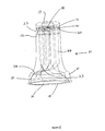
- FIG. 1 shows an external upper perspective view of an improved shisha head 10 according to the present invention.
- the shisha head 10 is hollow and comprises a circular upper bowl section 11 having a larger diameter and a lower circular tubular section 12 having a smaller diameter.
- the upper and lower sections 11 and 12 are connected by a tapered section 13 of the lower section 12.
- the upper end of the upper section 11 is substantially closed by a plate 14 located inside the upper edge of the upper section 11.
- a circumferential slot or slots 15 is defined between the edge of the plate 14 and the inner surface of the upper section 11. These slots 15 allow air to pass into the interior of the shisha head 10.
- the upper section 11 has a diameter of about 8.5cm and a height of about 2cm
- the lower section 12 has a diameter of about 4.5 cm and a height of about 9cm.
- FIG. 2 shows a lower perspective view of the shisha head 10. In figure 2 some parts are shown as transparent in order to allow the structure of the shisha head 10 to be readily understood.
- the lower section 12 has a plate 16 substantially closing the lower section 12 towards the lower end 12a of the lower section 12.
- the plate 16 is located about 2cm from the lower edge 12a of the lower section 12, and a outwardly extending part 12b of an outer surface of the shisha head 10 extends between the plate 16 and the lower edge 12a.
- a circular cylindrical wall 17 extends downwardly from the plate 16.
- the wall 17 is concentric with the lower circular tubular section 12 and has a diameter of about 2.2cm.
- the wall 17 extends downwardly about 2cm so that a bottom edge 17a of the wall 17 is level with the bottom edge 12a of the lower section 12.
- a small hole 18 passes through the lower plate 16 approximately in the centre of the plate 16. The hole 18 allows air to pass out of the interior of the shisha head 10.
- the shisha head 10 has dimensions selected so that it can be placed on top of a typical conventional shisha body in place of the conventional bowl.
- an upper edge of the shisha body 106 will be located between the wall 17 and the outwardly extending part 12b.
- a seal may be formed between the upper edge of the shisha body 106 and the plate 16.
- a grommet or other sealing element may be located on the upper edge of the shisha body 106, or between the wall 17 and the inner surface of the lower section 12, to improve the quality of this seal.
- an upper end of the tube 109 will be located inside the wall 17, so that the hole 18 will form an air passage allowing air to pass from the interior of the shisha head 10 and down the tube 109.
- a seal may be formed between the upper end of the tube 109 and the plate 16.
- a grommet or other sealing element may be located on the upper edge of the tube 109, or within the wall 17, to improve the quality of this seal.
- the dimensions of the illustrated example will allow the shisha head 10 to be used together with many conventional shisha bodies. In alternative examples different dimensions may be used. In any specific example the dimensions may be selected to cooperate with specific designs of shisha bodies.
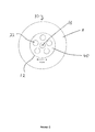
- FIG. 6 shows a plan view of the shisha head 10 from below, again with parts shown as transparent so that the interior components of the shisha head 10 are visible.
- Figure 7 shows a partially exploded view of the shisha head 10.
- the shisha head 10 contains six vapour generation capsules 20 and three batteries 21, which are arranged to supply power to the vapour generation capsules 20.
- Each vapour generation capsule 20 is cylindrical and about 7cm long.
- the vapour generation capsules 20 are oriented substantially vertically within the shisha head 10 and arranged with one capsule 20 in the centre of the shisha head, with the other capsules 20 arranged equidistantly in a circle around this central capsule.
- An inner plate 40 is located inside the lower section 12 extending parallel and spaced apart from the plate 16, so that the plates 16 and 40 define a mixing chamber 41 between them.
- the lower ends of the vapour generation capsules 20 are located within cylindrical tubular walls 22 extending upwardly from the upper, interior, surface of the inner plate 40 in order to support the capsules 20 and hold them in place. There is an aperture passing through the inner plate 40 inside each of the tubular walls 22 to allow air to pass into the mixing chamber 41 from a respective capsule 20.
- the components of the shisha head 10 define a number of air flow paths through the shisha head. Each air flow path passes through a slot 15 in the plate 14, through a capsule 20 into the mixing chamber 41, and through the hole 18. All of the air flow paths pass through the mixing chamber 41 and the hole 18.
- the vapour generation capsules 20 may be electrically powered atomizers or clearomizers.
- the batteries 21 are arranged in a battery compartment 23 located on the lower, interior, surface of the plate 14.
- the batteries 21 and the vapour generation capsules 20 are connected by wiring 24.
- the wiring 24 is shown schematically in the attached figures.
- the wiring 24 connects the batteries 21 to the capsules 20 so that each capsule 20 is connected to both a positive and a negative terminal of one of the batteries 21, as shown in figure 9 .
- each battery is electrically connected to two of the capsules 20 by the wiring 24, and each capsule 20 is electrically connected to a single battery 21 by the wiring 24, so that each battery 21 supplies two of the capsules 20 with power.
- the batteries 21 may be electrically connected together in parallel and the capsules 20 may also be electrically connected in parallel.
- each capsule 20 comprises an outer hollow tube 26 and an inner hollow tube 27 arranged concentrically.
- the space between the inner and outer tubes 26 and 27 contains a layer 28 of cotton threads soaked in an e-liquid.
- the e-liquid typically comprises propylene glycol, vegetable glycerine or polyethylene glycol 400, or a mixture thereof as a base, with active ingredients dissolved in or mixed with this base.
- the active ingredients may comprise nicotine and/or flavourings, as discussed in more detail below.
- a plurality of resistance heater wires pass through the layer 28. In the illustrated example the heater wires are arranged to form a plurality of coils 29 distributed within the layer 28, with each coil 29 surrounding a group of cotton threads.
- An airflow sensor 25 is positioned at the top of each capsule 20.
- Each airflow sensor 25 is located adjacent the top of the outer hollow tube 26 of the respective capsule 20 and is arranged to detect any flow of air through the capsule 20 and into the mixing chamber 41. When each airflow sensor 25 detects an air flow through a respective capsule 20 the airflow sensor 25 switches on the supply of electrical power from a battery 21 to the respective capsule 20.
- the e-liquid within the capsules 20 which is used to produce the vapour may comprise a solution of e-liquid which contains nicotine so that the vapour comprises a mixture of e-liquid with nicotine vapour.
- the e-liquid within the capsules 20 may additionally, or alternatively, comprise one or more vaporisable flavourings so that the vapour is flavoured.
- the cotton threads of the layer 28 are soaked in water, with the amount of water contained in the capsule 20 being sufficient for the intended useage life of the capsule 20.
- the capsules may include a water reservoir to supply water to the cotton threads to replace the water which is vapourised.
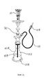
- the shisha head 10 is placed on top of a shisha body 30, as shown in figure 12 .
- the shisha body 30 is a conventional shisha body as shown in figure 12 , and the usual bowl used with the shisha body 30 is replaced by the shisha head 10 of the present invention.
- the shisha head 10 is arranged so that the first tube 109 of the shisha body 30 is in communication with the hole 18in the bottom of the shisha head 10.
- vapour When supplied with electrical power the capsules 20 generate vapour, which may also comprise nicotine and/or flavour vapour when nicotine and/or flavours.
- vapour from each of the capsules 20 passes into the mixing chamber 41 where the vapour and airflows from the different capsules 20 intermingle.
- the vapour generated by the capsules 20 then leaves the mixing chamber 41 and the shisha head 10, and passes through the hole 18 in the bottom of the shisha head 10 into the first tube 109 of the shisha body 30.
- the vapour then bubbles through the water 108 into the air space 112 within the chamber 107.
- the vapour is then sucked along the second tube 111 to the mouthpiece 110 and can be inhaled by the user.
- the shisha head according to the present invention may allow a user to inhale vapour from the shisha, providing a similar experience to a conventional shisha without the potential health risks of inhaling tobacco smoke. Further, the shisha head according to the present invention may allow a user to enjoy a similar experience to a conventional shisha without breaking legal restrictions on smoking.
- the shisha head according to the present invention may also allow a user to ingest nicotine by inhaling the vapour.
- the shisha head according to the present invention may provide an enhanced user experience.
- the shisha head 20 is placed on top of a shisha body 30, as shown in figure 13 .
- the shisha body 30 is a conventional shisha body, as shown in previous example.
- flavour substances are added to the water 108 by dissolving a soluble flavour capsule 31 in the water 108.
- This flavouring may flavour the water resulting in an increased flavoured vapour provided to the user.
- flavouring dissolved in the water in the shisha body according to the present invention may provide an enhanced user experience.
- flavouring material may be added to the water 108 in a different manner.
- the flavouring material may be added in the form of a soluble tablet or powder, or a concentrated solution.
- each vapour generating capsule is associated with a separate dedicated air flow sensor which controls the supply of power to that capsule.
- This arrangement may provide improved reliability through redundancy because even if one or more of the air flow sensors fails to operate in response to an air flow, the remaining air flow sensors will still activate their respective capsules and generate vapour.
- one or more air flow sensors may be used to control the supply of power to all of the capsules. These air flow sensors may not be associated with capsules.
- a single air flow sensor may be arranged to sense air flow through the hole 18 and arranged to control the supply of power to all of the capsules.
- the central capsule may be replaced by a single air flow sensor arranged to control the supply of power to all of the remaining capsules.
- the shisha head is intended to only be used for a single shisha session, that is a single "smoking" session, and then discarded.
- the shisha head may be designed for a longer useable life.
- the useable active life of the shisha head is determined by the amount of vapourisable water contained in the vapourizer capsules and the amount of power in the batteries.
- the shisha head may be designed to be refurbished to allow repeated use.
- the shisha may further comprise a display to indicate information regarding usage to the user.
- the display may indicate the number of vapourization operations carried out, or the number of vapourization operations remaining before the shisha is exhausted. In some examples the display may indicate the remaining charge level of the battery or batteries.
- the shisha contains batteries as a power source. In other examples other power sources may be used.
- vapourizer capsules and batteries in the described examples are not essential. Different numbers may be used in other examples.
- batteries as a power supply is not essential. In other examples other forms of power supply may be used.
Landscapes
- Respiratory Apparatuses And Protective Means (AREA)
- Devices For Medical Bathing And Washing (AREA)
Applications Claiming Priority (1)
| Application Number | Priority Date | Filing Date | Title |
|---|---|---|---|
| GB1315101.4A GB2519934B (en) | 2013-08-23 | 2013-08-23 | Improved shisha |
Publications (1)
| Publication Number | Publication Date |
|---|---|
| EP2845497A1 true EP2845497A1 (de) | 2015-03-11 |
Family
ID=49355831
Family Applications (1)
| Application Number | Title | Priority Date | Filing Date |
|---|---|---|---|
| EP14250100.6A Withdrawn EP2845497A1 (de) | 2013-08-23 | 2014-08-22 | Verbesserte Wasserpfeife |
Country Status (3)
| Country | Link |
|---|---|
| US (1) | US20150053221A1 (de) |
| EP (1) | EP2845497A1 (de) |
| GB (1) | GB2519934B (de) |
Cited By (6)
| Publication number | Priority date | Publication date | Assignee | Title |
|---|---|---|---|---|
| DE102015009276A1 (de) * | 2015-07-16 | 2017-01-19 | Torsten Niemeitz | Einheit zur Verflüchtigung von Nikotin, Aromen und therapeutisch einsetzbaren Stoffen in einem Vaporizer |
| WO2018073742A1 (en) * | 2016-10-21 | 2018-04-26 | Philip Morris Products S.A. | Shisha device having air flow path |
| KR20180134873A (ko) * | 2016-04-11 | 2018-12-19 | 필립모리스 프로덕츠 에스.에이. | 연소 없이 기재를 가열하기 위한 시샤 장치 |
| CN109068725A (zh) * | 2016-04-11 | 2018-12-21 | 菲利普莫里斯生产公司 | 用于加热基质而不燃烧的水烟装置 |
| US10561172B2 (en) | 2016-03-07 | 2020-02-18 | Wallbrooke Investments Ltd. | Inductive heating apparatus and related method |
| WO2022248390A1 (de) * | 2021-05-26 | 2022-12-01 | Joachim Hellstern | Heizaufsatz für einen rauchkopf einer wasserpfeife |
Families Citing this family (17)
| Publication number | Priority date | Publication date | Assignee | Title |
|---|---|---|---|---|
| CN112772973B (zh) | 2014-05-12 | 2025-01-21 | 空气Ip控股有限公司 | 一种可燃材料的器皿 |
| USD752727S1 (en) * | 2014-05-20 | 2016-03-29 | Vape Holdings, Inc. | Ceramic vaporizer |
| US9775382B2 (en) * | 2015-06-15 | 2017-10-03 | Dan Wang | Multiple mode vapor generator |
| KR20170041055A (ko) | 2015-10-06 | 2017-04-14 | 삼성에스디에스 주식회사 | 사용자 위치 추적 방법 |
| US10694781B2 (en) * | 2016-10-07 | 2020-06-30 | James Ronald Martin | Electronic pipe vaporizer |
| RU2645568C1 (ru) * | 2016-10-10 | 2018-02-21 | Алексей Иванович Бондарь | Устройство для формирования курительной газовой смеси в кальяне |
| GB201713679D0 (en) | 2017-08-25 | 2017-10-11 | Nicoventures Holdings Ltd | Vapour provision systems |
| GB201713681D0 (en) * | 2017-08-25 | 2017-10-11 | Nicoventures Holdings Ltd | Vapour provision systems |
| US10327468B2 (en) * | 2017-10-11 | 2019-06-25 | Sebastian Scholl | System and methods for imparting flavor in liquid filtration inhalation apparatuses |
| JP7434300B2 (ja) | 2018-06-15 | 2024-02-20 | エーエフ ディベロップメント ホールディング リミテッド | 使用済みカプセルを放出するための機構を有する水パイプ |
| EP3806669B1 (de) | 2018-06-15 | 2025-11-26 | AIR IP Holdings Limited | Wasserpfeife mit passgenauem sitz für eine kapsel |
| PL3843563T3 (pl) | 2018-08-29 | 2024-06-03 | Air IP Holdings Limited | Wodna fajka z bezzaworową ssącą rurką |
| CN109123783A (zh) * | 2018-09-29 | 2019-01-04 | 刘海伟 | 一种具有水蒸气发生功能的卷烟抽吸装置 |
| US12089642B2 (en) * | 2018-11-13 | 2024-09-17 | Philip Morris Products S.A. | Heater array to heat aerosol-generating article |
| RU2685870C1 (ru) * | 2018-11-21 | 2019-04-23 | Лерон Григорьевич Биняминов | Устройство для нагрева табакосодержащей курительной смеси в чаше кальяна |
| ES2972465T3 (es) * | 2019-12-02 | 2024-06-12 | Philip Morris Products Sa | Dispositivo de narguile con canales |
| CN116138506A (zh) * | 2021-11-22 | 2023-05-23 | 贵州中烟工业有限责任公司 | 气溶胶产生方法及装置 |
Citations (2)
| Publication number | Priority date | Publication date | Assignee | Title |
|---|---|---|---|---|
| DE202005015795U1 (de) * | 2004-10-26 | 2005-12-08 | Liu, Chun-Liang, Yung Kang | Elektrische Heizvorrichtung für eine Wasserpfeife |
| US20120042884A1 (en) * | 2010-08-20 | 2012-02-23 | Magic Herbal S.A.R.L. | Electronic atomization hookah |
Family Cites Families (11)
| Publication number | Priority date | Publication date | Assignee | Title |
|---|---|---|---|---|
| US8550091B2 (en) * | 2008-11-24 | 2013-10-08 | Kannel Management, Llc | Electrically heated water pipe smoking device |
| US9095174B2 (en) * | 2009-12-20 | 2015-08-04 | Sis Resources Ltd. | Electronic hookah |
| AU2010236019A1 (en) * | 2010-05-21 | 2011-12-08 | Magic Herbal S.A.R.L. | An electronic atomization hookah |
| CN201860741U (zh) * | 2010-11-24 | 2011-06-15 | 温州威林五金制品有限公司 | 一种电子水烟筒 |
| WO2014020539A1 (en) * | 2012-08-02 | 2014-02-06 | White Mist Electronics Inc | Combustion free and tobacco free smoking device |
| US8757170B2 (en) * | 2012-09-21 | 2014-06-24 | Firas Kaplani | Waterless electronic hookah machine |
| US20140144452A1 (en) * | 2012-11-27 | 2014-05-29 | Tuanfang Liu | Electronic Hookah and Its Application Method |
| USD702876S1 (en) * | 2012-12-10 | 2014-04-15 | Shuigen Liu | Tobacco vaporizer |
| USD731113S1 (en) * | 2013-09-11 | 2015-06-02 | Changming Wu | Electronic cigarette |
| CA2847702A1 (en) * | 2014-03-28 | 2015-09-28 | Boris Giller | Adapter for connecting automatic electronic vaporizer to a traditional shisha |
| USD745212S1 (en) * | 2014-07-14 | 2015-12-08 | Fantasia Distribution, Inc. | Electronic hookah bowl |
-
2013
- 2013-08-23 GB GB1315101.4A patent/GB2519934B/en not_active Expired - Fee Related
-
2014
- 2014-08-22 EP EP14250100.6A patent/EP2845497A1/de not_active Withdrawn
- 2014-08-22 US US14/466,499 patent/US20150053221A1/en not_active Abandoned
Patent Citations (2)
| Publication number | Priority date | Publication date | Assignee | Title |
|---|---|---|---|---|
| DE202005015795U1 (de) * | 2004-10-26 | 2005-12-08 | Liu, Chun-Liang, Yung Kang | Elektrische Heizvorrichtung für eine Wasserpfeife |
| US20120042884A1 (en) * | 2010-08-20 | 2012-02-23 | Magic Herbal S.A.R.L. | Electronic atomization hookah |
Cited By (13)
| Publication number | Priority date | Publication date | Assignee | Title |
|---|---|---|---|---|
| DE102015009276A1 (de) * | 2015-07-16 | 2017-01-19 | Torsten Niemeitz | Einheit zur Verflüchtigung von Nikotin, Aromen und therapeutisch einsetzbaren Stoffen in einem Vaporizer |
| US10561172B2 (en) | 2016-03-07 | 2020-02-18 | Wallbrooke Investments Ltd. | Inductive heating apparatus and related method |
| US11707085B2 (en) | 2016-03-07 | 2023-07-25 | Evyra Sa | Inductive heating apparatus and related method |
| KR20220119164A (ko) * | 2016-04-11 | 2022-08-26 | 필립모리스 프로덕츠 에스.에이. | 연소 없이 기재를 가열하기 위한 시샤 장치 |
| JP2019514359A (ja) * | 2016-04-11 | 2019-06-06 | フィリップ・モーリス・プロダクツ・ソシエテ・アノニム | 燃焼せずに基体を加熱するシーシャ装置 |
| CN109068725A (zh) * | 2016-04-11 | 2018-12-21 | 菲利普莫里斯生产公司 | 用于加热基质而不燃烧的水烟装置 |
| CN109068725B (zh) * | 2016-04-11 | 2022-02-15 | 菲利普莫里斯生产公司 | 用于加热基质而不燃烧的水烟装置 |
| KR20180134873A (ko) * | 2016-04-11 | 2018-12-19 | 필립모리스 프로덕츠 에스.에이. | 연소 없이 기재를 가열하기 위한 시샤 장치 |
| US11751602B2 (en) | 2016-04-11 | 2023-09-12 | Philip Morris Products S.A. | Shisha device for heating a substrate without combustion |
| EA035963B1 (ru) * | 2016-10-21 | 2020-09-07 | Филип Моррис Продактс С.А. | Кальянное устройство, имеющее путь потока воздуха |
| US11089814B2 (en) | 2016-10-21 | 2021-08-17 | Philip Morris Products S.A. | Shisha device having air flow path |
| WO2018073742A1 (en) * | 2016-10-21 | 2018-04-26 | Philip Morris Products S.A. | Shisha device having air flow path |
| WO2022248390A1 (de) * | 2021-05-26 | 2022-12-01 | Joachim Hellstern | Heizaufsatz für einen rauchkopf einer wasserpfeife |
Also Published As
| Publication number | Publication date |
|---|---|
| GB2519934B (en) | 2018-03-28 |
| GB201315101D0 (en) | 2013-10-09 |
| US20150053221A1 (en) | 2015-02-26 |
| GB2519934A (en) | 2015-05-13 |
Similar Documents
| Publication | Publication Date | Title |
|---|---|---|
| EP2845497A1 (de) | Verbesserte Wasserpfeife | |
| JP7273905B2 (ja) | 燃焼せずに基体を加熱するシーシャ装置 | |
| US9351522B2 (en) | Cartomizer e-cigarette | |
| AU2019337805B2 (en) | Wicking element for aerosol delivery device | |
| KR102534534B1 (ko) | 교체 가능한 심지 및 히터 조립체를 구비한 에어로졸 송출 장치 | |
| JP2022504600A (ja) | 視覚的表示を有するエアロゾル送達装置 | |
| ES2540990T3 (es) | Cigarrillo simulado electrónico multifuncional combinado | |
| ES2758036T3 (es) | Aparato para la creación de extracto de tabaco líquido | |
| TW201208720A (en) | Atomizer-vaporizer for a personal vaporizing inhaler | |
| TW201143825A (en) | Personal vaporizing inhaler with internal light source | |
| US20220400774A1 (en) | Power Optimization Electronic Cigarette Device | |
| US12127594B2 (en) | Heat-not-burn smoking device | |
| US20260000125A1 (en) | Inductively heated aerosol delivery device consumable | |
| RU129368U1 (ru) | Портативный электронный ингалятор | |
| KR102385864B1 (ko) | 에어로졸 생성 장치 | |
| CN206137192U (zh) | 采用直立式陶瓷雾化单元的电子烟雾化器 | |
| KR20120109256A (ko) | 카트리지 및 이를 포함하는 전자 담배 | |
| KR101522699B1 (ko) | 전자 담배 | |
| JP7838082B2 (ja) | エアロゾル生成装置及びその動作方法 | |
| CN120154135A (zh) | 一种气溶胶供应系统 | |
| KR20230055908A (ko) | 에어로졸 생성장치 및 그 동작방법 | |
| KR20070065194A (ko) | 금연 보조기구 | |
| CN118102933A (zh) | 气溶胶产生装置及其操作方法 |
Legal Events
| Date | Code | Title | Description |
|---|---|---|---|
| 17P | Request for examination filed |
Effective date: 20140822 |
|
| AK | Designated contracting states |
Kind code of ref document: A1 Designated state(s): AL AT BE BG CH CY CZ DE DK EE ES FI FR GB GR HR HU IE IS IT LI LT LU LV MC MK MT NL NO PL PT RO RS SE SI SK SM TR |
|
| AX | Request for extension of the european patent |
Extension state: BA ME |
|
| PUAI | Public reference made under article 153(3) epc to a published international application that has entered the european phase |
Free format text: ORIGINAL CODE: 0009012 |
|
| R17P | Request for examination filed (corrected) |
Effective date: 20150910 |
|
| STAA | Information on the status of an ep patent application or granted ep patent |
Free format text: STATUS: THE APPLICATION HAS BEEN WITHDRAWN |
|
| 18W | Application withdrawn |
Effective date: 20170907 |