EP2845529A1 - Komponente eines Küchengerät - Google Patents
Komponente eines Küchengerät Download PDFInfo
- Publication number
- EP2845529A1 EP2845529A1 EP14180780.0A EP14180780A EP2845529A1 EP 2845529 A1 EP2845529 A1 EP 2845529A1 EP 14180780 A EP14180780 A EP 14180780A EP 2845529 A1 EP2845529 A1 EP 2845529A1
- Authority
- EP
- European Patent Office
- Prior art keywords
- component
- tool
- coupling
- cutting edges
- pot
- Prior art date
- Legal status (The legal status is an assumption and is not a legal conclusion. Google has not performed a legal analysis and makes no representation as to the accuracy of the status listed.)
- Granted
Links
Images



Classifications
-
- A—HUMAN NECESSITIES
- A47—FURNITURE; DOMESTIC ARTICLES OR APPLIANCES; COFFEE MILLS; SPICE MILLS; SUCTION CLEANERS IN GENERAL
- A47J—KITCHEN EQUIPMENT; COFFEE MILLS; SPICE MILLS; APPARATUS FOR MAKING BEVERAGES
- A47J43/00—Implements for preparing or holding food, not provided for in other groups of this subclass
- A47J43/04—Machines for domestic use not covered elsewhere, e.g. for grinding, mixing, stirring, kneading, emulsifying, whipping or beating foodstuffs, e.g. power-driven
- A47J43/07—Parts or details, e.g. mixing tools, whipping tools
- A47J43/0705—Parts or details, e.g. mixing tools, whipping tools for machines with tools driven from the upper side
- A47J43/0711—Parts or details, e.g. mixing tools, whipping tools for machines with tools driven from the upper side mixing, whipping or cutting tools
Definitions
- the invention relates to a component of a kitchen appliance having a coupling for fastening a tool and a cup-shaped sieve part with a cup bottom provided with passages and a cup casing surrounding the bottom of the pot, wherein the screen member has on an inner side cutting edges which are substantially radially to an axis of the coupling are aligned.
- WO 2008/031803 A1 discloses a passing device, in particular for use with a food processor, comprising a cup-shaped screen member and a passing tool with a hub can be coupled to a drive shaft to rotatably drive the pass tool about an extending in the longitudinal direction of a pot shell of the screen portion rotation axis, and at least one of the Hub portion radially outwardly extending passing wing.
- the pot jacket has along its circumference on its inside at least one niche-like portion which has a greater distance from the axis of rotation than another portion of the inside of the pot shell.
- the leading edge of the passing wing is provided in the intended direction of rotation at least on a section with a first cutting edge to crush passages.
- the patent application GB 2456538 A discloses a blender attachment for a hand blender comprising an elongated housing adapted at one end to receive a motorized shaft and having at the other end a bleaching tool comprising a rotor mounted within an open cylindrical cavity the cavity is limited by a slotted jacket.
- the patent application WO 2012/071608 A1 describes a blender for pureeing potatoes and similar foods, the device including a drive unit.
- the device additionally comprises a purge arrangement, which starts from the said drive unit.
- the said purger arrangement comprises a jacket element and a puréeing element, which operates within said jacket element. In the process, pureed potatoes and similar foods are pressed through openings in a side wall of said jacket element.
- the patent US 624107 claims a device for emulsification or similar treatment of materials comprising a rotatable shaft, at its free end an element with cutting edges is provided.
- the apparatus further includes a cylindrical chamber closed at its upper end and supported by said shaft.
- attached to an upper disc is a metal cylinder having a central opening in its base and slots in its side wall.
- the European patent application EP 0943278 A1 describes a kitchen appliance for cutting foodstuffs, such as fruit, vegetables or the like, with a cutting knife mounted in a holder, which has two cutting edges whose cutting edges extend substantially in a common cutting plane and are arranged at an angle to one another.
- the cutting blade is formed in a disk rotating about a rotation axis perpendicular to the cutting plane, with one of the cutting edges substantially closer to the axis of rotation lies as the other cutting edge.
- the two cutting edges are concavely or convexly curved.
- the layout DE 1224006 describes a scissors-type crushing device for food or the like, consisting of arranged in cup counter cutting and circulating therein, the material to be crushed the counter cutting and feeding it in collapsing blade-shaped knife, in which the teeth formed on the type of saw teeth inside, the knife have opposing cutting edges with respect to the cutting edge outwardly offset edges, the cutting edges with the two outer cutting edges of the substantially rectangular knife cooperate, while the lower longitudinal edge of the knife acts directly on the material to be cut.
- the blade wings are twisted so that the lower edge of the knife leads the knife edge in the direction of the upper knife edge, so that the material to be cut is conveyed upwards into the pot provided with the counter cut edges.
- the patent application discloses DE 1219640 a scissors-type crushing device for foodstuffs or the like, consisting of counter-blades arranged in the form of pots and a sheet-like knife which circulates therein and feeds the material to be crushed to the counter-cutting edges and, in cooperation therewith, comminuting them.
- Teeth designed in the manner of sawteeth have internal cutting edges directed counter to the blade with edges offset outwards relative to the cutting edge, the cutting edges interacting with the two external cutting edges of the essentially rectangular blade, while the lower longitudinal cutting edge of the knife acts directly on the cutting material.
- the undercut formation of the single fixed tooth has the advantage that the cutting edge of the tooth following in the direction of rotation of the knife is exposed, so that the device can work better and faster.
- the rectangular blade-shaped knife is firmly connected in its center with the drive shaft and is also in a vertical drive shaft in a vertical plane, the blade wings with respect to the blade rotation direction can be bent back to form wedge-shaped spaces between the blade wings and the inner pot wall.
- the counter-cutting edges may be parallel to the peripheral cutting edges, or they may be intersecting cutting edges.
- the object of the invention is to provide an improved component of a kitchen appliance.
- the object is to provide an improved kitchen appliance with such a component.
- the object of the invention is achieved by a component of a kitchen appliance with a coupling for fastening a tool and a pot-shaped sieve with a provided with openings pot bottom and a cup bottom surrounding the pot shell pot jacket.
- the screen part on an inner side cutting edges, which are aligned substantially radially to an axis of the coupling.
- at least 10% of the average openings measure at least 0.2 mm.
- the object of the invention is also achieved by a kitchen appliance with the said component.
- the diameter of the passage openings refers to the largest distance between two points at the boundary of the respective passage opening.
- the fact that the cutting edges are oriented substantially radially to the axis of the coupling means that the cutting edges can deviate up to 30 degrees from the radial direction with respect to the axis.
- the cutting edges deviate by less than 20 degrees, more preferably less than 10 degrees, and most preferably by less than 5 degrees, with respect to a radial direction to the axis.
- the cutting edges are aligned radially to the axis and thus deviate by 0 degrees from the radial direction.
- the cutting edges are straight, but alternatively the cutting edges may be curved.
- the curvature of the cutting edges in the direction of rotation of a tool placed on the coupling is leading or lagging.
- the passage openings have a diameter of at least 0.3 mm, particularly preferably 0.4 mm, particularly preferably 0.5 mm, particularly preferably 1 mm, particularly preferably 1.5 mm, particularly preferably 2 mm, especially preferably 3 mm, more preferably 5 mm and most preferably 7 mm.
- said diameters meet at least 20%, more preferably at least 30%, especially preferably at least 50%, particularly preferably at least 70%, particularly preferably at least 90% and very particularly preferably to all passage openings in the screen part to.
- the cutting edges are evenly distributed on the inside of the screen part, so that the cutting edges divide the bottom of the pot into segments of the same size.
- the segments have different sizes, e.g. because the cutting edges are distributed irregularly over the bottom of the pot.
- the component has at least three cutting edges.
- the component has at least 5, more preferably at least 7, more preferably at least 10, most preferably at least 15, most preferably at least 20 and most preferably at least 30 cutting edges.
- the number of cutting edges is preferably at most 100, more preferably at most 70 and very particularly preferably at most 50. By a suitable number of cutting edges a material to be processed can be crushed particularly quickly.
- the bottom of the pot has less than 500 openings.
- the pot bottom has less than 400, more preferably less than 300, and most preferably less than 250 passages.
- the bottom of the pot more than 10, more preferably more than 20, more preferably more than 50, more preferably more than 100 and most preferably more than 150 passages on.
- the passage openings take on an elongated shape. This preferably applies to at least 10%, particularly preferably at least 20%, particularly preferably at least 50%, particularly preferably at least 70%, particularly preferably at least 90% and very particularly preferably all passage openings in the screen part.
- the fact that the passages are elongated means that these are from Diverge from a circular shape, for example, are oval.
- the passage openings take the form of a classical stadium, ie, that their shape consists of a rectangle, which has in each case a semicircle on two opposite sides.
- the passage openings may also be circular, polygonal and in particular rectangular.
- the longitudinal diameter of the passage openings is aligned in the radial direction to the axis of the coupling. This preferably applies to at least 10%, particularly preferably at least 20%, particularly preferably at least 50%, particularly preferably at least 70% and very particularly preferably all passage openings in the screen part.
- a suitable orientation of the passage openings By a suitable orientation of the passage openings, a large number of passage openings between two cutting edges can be arranged.
- the pot bottom of the screening part is curved outward.
- the screen member has a convex shape, in particular, the pot bottom of the screen member is preferably convex when viewed from the outside.
- the pot bottom is preferably concave.
- the coupling has a thread.
- a tool can be reversibly attached to the coupling by a thread.
- the thread is a multi-start thread, particularly preferably a three-start thread.
- the pitch of the thread can be chosen particularly high, so that a tool with only a small rotation can be attached and removed again. If the axle is freely rotatable, it is possible by a high thread pitch in a multi-thread that a user can connect the tool with an axial movement with the clutch and can be replaced by an opposite movement of the clutch.
- the axle can rotate in such a way that a screw connection between the tool and clutch can result or at opposite movement can solve a screw connection between the tool and coupling.
- the thread on the coupling is an external thread.
- the coupling can be cleaned very easily.
- the thread of the coupling has a pitch of at least 2 mm, more preferably at least 5 mm and most preferably at least 10 mm. By a particularly high pitch of the thread of the coupling, the tool can be very easily attached to the coupling and removed from it.
- the coupling has at least one latching means.
- the locking means is preferably adapted to serve for locking with the tool.
- the latching means preferably comprises a protrusion, a recess and / or a notch.
- the locking means may e.g. a detent, a detent groove and / or a circumferential ring include.
- the locking means can secure the position of the tool on the coupling. A noticeable locking of the tool with the locking means of the coupling can signal a user the correct positioning of the tool.
- the kitchen appliance is preferably a hand blender.
- the component is preferably the component of a hand blender.
- the kitchen utensil may also be e.g. a food processor or a mixer.
- Such kitchen appliances can be supplemented by components with cutting edges, so that a particularly advantageous treatment of processed material can result.
- the component is a pureeing component.
- the component is - preferably with attached tool - suitable for a functionsgut, such as. cooked vegetables, to puree.
- the tool is preferably designed as a turntable, screw and / or knife.
- the tool preferably rotates in such a way that material to be processed is moved over the cutting edges and is comminuted by these.
- the component is the component of a blender bar.
- the component is removable from the kitchen appliance.
- the component can be detached non-destructively from the kitchen appliance and connected to it again. So a kitchen appliance can be operated with several different components.
- the component is firmly connected to the kitchen appliance, so that the component can not be removed from the kitchen appliance nondestructively.
- the kitchen appliance can be designed so particularly stable.
- the pot jacket has recesses.
- the recesses are preferably elongated. It is preferred that the longest diameter of the recesses of the pot shell is aligned parallel to the axis of the coupling.
- the ratio of the area of openings in the screen member to an inner surface of the screen member is at least 5%. At least 5% of the inner surface of the screen member are provided with openings. Openings are in this sense both recesses in Topfmantel as well as openings in the bottom of the pot.
- the ratio of the surface area of the openings to the inner surface of the screening part is at least 10%, particularly preferably at least 20%, particularly preferably at least 30% and preferably at most 60%, particularly preferably at most 50% and very particularly preferably at most 40%.
- the cutting edges are aligned on the inside of the screen member against a rotational direction of the coupling.
- a tool attached to the coupling preferably rotates in a certain direction.
- the cutting edges are preferably arranged so that the processing material brought into rotation by the tool strikes and is crushed by the cutting edges.
- it is possible that the cutting edges are aligned in the direction of rotation of the coupling.
- the FIGS. 1 shows the kitchen appliance 1 according to the invention designed as a hand blender 2.
- a blending component 4 is placed as a component 3.
- the kitchen appliance 1 has a switch 5, with which an electric motor 6 (not shown) in the hand blender 2 can be switched on and off.
- component 3 has an axis 7 with a coupling 8, which serves to fasten a tool 9.
- the coupling 8 a multi-thread 10 on.
- FIG. 2 shows the inventive component 3 with attached tool 9.
- the component 3 has a tool 9 partially surrounding the screen member 11.
- the screen member 11 is cup-shaped and has a pot bottom 12 and a pot jacket 13, which surrounds the bottom of the pot 12 like a collar.
- the bottom of the pot 12 has through openings 14.
- 13 recesses 15 are in the pot casing.
- the tool 9 is on a in FIG. 2 not shown coupling 8 of the pureeing 4 plugged.
- the tool 9 is formed in this embodiment as a pruning tool 16.
- the blender tool 16 essentially takes the form a propeller with two wings 17 a.
- the tool 9 of the component 3 rotates clockwise. In this case, processing material is pressed by the tool 9 to the pot bottom 12 and the pot casing 13, so that the material to be processed is crushed and exits through the recesses 15 in the pot casing 13 and through the passage openings 14 in the pot bottom.
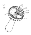
- the cutting edges 31 can be seen on the inner surface of the pot bottom 12 of the component 3. In this embodiment, the cutting edges 31 are aligned against the direction of rotation of the tool 9.
- the blending tool 16 can set material to be processed into rotation.
- the rotating material to be processed between blending tool 16 and pot bottom 12 can be moved over the cutting edges 31, so that they shred the material to be processed. In this way, a particularly fast and effective comminution of processed material can result.
- FIG. 3 shows the blending component without the tool.
- the coupling 8 with its multi-thread 10 can be seen particularly clearly.
- the elongated, oval passage openings 14 in the bottom of the pot 12 are here aligned radially to the coupling 8.
- the recesses 15 in the pot jacket 13 are also elongated and aligned parallel to the axis 7, not shown here, the pureeing component 4.
- the cutting edges 31 are also in FIG. 3 to recognize. It can also be seen that the cutting edges 31 do not continue to the edge of the coupling 8, but are spaced from it by about 0.5 to 1 cm. It can also be seen that the cutting edges 31 divide the bottom of the pot 12 into narrow segments, these segments being twisted relative to one another, resulting in a fan-shaped appearance. Due to the angled segments, a rotating material to be processed can be crushed particularly effectively.
- FIG. 4 shows the propeller-like blurring tool 16 with an internal thread 18, which on the external thread of in FIG. 3 shown coupling 8 can be plugged.
- FIG. 5 shows the longitudinal section through the axis 7 of the pureeing component 4 with attached blending tool 16. The aligned parallel to the axis 7 recesses 15 in Topfmantel 13 are clearly visible.
- the pivot bearing 20 is designed as a sliding bearing 21.
- a sealing disc 22 is mounted above the sliding bearing 21, which prevents slipping of the axis 7.
- FIGS. 6 and 7 show the clutch 8 with its multi-threaded external thread 19 and a locking means 23 which is formed as an annular latching projection 24 which can latch with a latching means 25 of the tool 9.
- FIG. 7 shows a section through the tool 9, which is locked to the clutch 8. In this case, the multi-thread 10 of the clutch 8 with its threads 26 is clearly visible. In addition, it is shown that the annular detent projection 24 of the coupling 8 is latched to the latching means 25 of the tool 9.
- the latching means 25 of the tool 9 is designed in this embodiment as a latching groove 27 of the tool 9. The locking of the tool 9 with the coupling 8 is facilitated by cuts 28 of the tool 9.
- the incisions 28 are made in this embodiment of a tool 9 for a hand blender 2, starting from the surface of the tool 9, which is the motor 6 of the blender 2 during operation of the blender 2 closest.
- the incisions 28 provide flexibility in the area of the screw-in opening of the tool 9, so that the latching means 23 of the coupling 8 can engage particularly easily with the latching means 25 of the tool 9.
- the locking means 25 of the tool 9 is also designed here so that the orientation of the tool 9 relative to the clutch 8 is clearly defined.
- 8 projections may be provided on the coupling, which can cooperate with the incisions 28 of the tool 9.
- the clutch 8 also has a ring 29 which can support the overhang 30 of the tool 9 when the tool 9 is mounted on the coupling.
- the overhang 30 is the part of the tool 9, which is in the mounted state of the tool 9 on the coupling 8 between the ring 29 of the coupling 8 and locking projection 24 of the clutch 8.
- the tool 9 can be screwed by turning the clutch 8. If the component 3 is not connected to the kitchen appliance 1 and the axis 7 is freely rotatable, then the tool 9 can also be pushed by a simple axial pressing on the clutch 8. Since the multi-thread 10 of the clutch 8 in the embodiment in FIG. 6 is particularly steep, can rotate by pushing the tool 9 on the clutch 8, the axis 7 such that the tool 9 is screwed onto the clutch 8. To attach the clutch 8 to the tool 9 is a locking projection 24 on the coupling 8 and a locking groove 27 on the tool 9, which lock together by sliding. When the component 3 is connected to the kitchen appliance 1, the tool 9 can be unscrewed by rotation of the clutch 8.
- the tool 9 can also be easily removed from the coupling 8, wherein the coupling 8 rotates during the removal in such a way that the tool 9 is unscrewed from the coupling 8. If, when using the kitchen appliance 1 processing material between tool 9 and Clutch 8 caught, so the tool 9 can unscrew by the high pitch of the multi-thread 10 of the clutch 8 of the clutch 8, so that damage to the kitchen appliance 1 is avoided.
- the multi-start thread 10 the torque at which a material break is significantly higher than in known from the prior art solutions. The end position of the tool 9 on the clutch 8 is felt by the user by the latching of the locking means 23, 25 of the clutch 8 and the tool 9.
Landscapes
- Engineering & Computer Science (AREA)
- Mechanical Engineering (AREA)
- Food Science & Technology (AREA)
- Food-Manufacturing Devices (AREA)
- Crushing And Pulverization Processes (AREA)
Abstract
Description
- Die Erfindung betrifft eine Komponente eines Küchengeräts mit einer Kupplung zur Befestigung eines Werkzeugs sowie einem topfförmigen Siebteil mit einem mit Durchtrittsöffnungen versehenen Topfboden und einem den Topfboden kragenförmig umschließenden Topfmantel, wobei das Siebteil auf einer Innenseite Schneidkanten aufweist, die im Wesentlichen radial zu einer Achse der Kupplung ausgerichtet sind.
- Komponenten von Küchengeräten mit topfförmigen Siebteilen sind aus dem Stand der Technik bekannt. Die Patentanmeldung
WO 2008/031803 A1 offenbart ein Passiergerät, insbesondere für die Verwendung mit einer Küchenmaschine, umfassend ein topfförmig ausgebildetes Siebteil und ein Passierwerkzeug mit einem an eine Antriebswelle ankuppelbaren Nabenteil, um das Passierwerkzeug um eine in Längsrichtung eines Topfmantels des Siebteils verlaufende Drehachse rotierend anzutreiben, und wenigstens einem sich von dem Nabenteil radial nach außen erstreckenden Passierflügel. Der Topfmantel weist entlang seines Umfangs auf seiner Innenseite mindestens einen nischenartigen Abschnitt auf, der einen größeren Abstand von der Drehachse hat als ein anderer Abschnitt der Innenseite des Topfmantels. Die voreilende Kante des Passierflügels ist bei der vorgesehenen Drehrichtung wenigstens auf einem Teilabschnitt mit einer ersten Schneidkante ausgestattet, um Passiergut zu zerkleinern. - Die Patentanmeldung
GB 2456538 A - Die Patentanmeldung
WO 2012/071608 A1 beschreibt ein Püriergerät zum Pürieren von Kartoffeln und ähnlichen Lebensmitteln, wobei das Gerät eine Antriebseinheit einschließt. Das Gerät umfasst zusätzlich eine Pürieranordnung, die von der besagten Antriebseinheit ausgeht. Die besagte Pürieranordnung umfasst ein Mantelelement und ein Pürierelement, das innerhalb des besagten Mantelelements operiert. Dabei werden pürierte Kartoffeln und ähnliche Nahrungsmittel durch Öffnungen in einer Seitenwand des besagten Mantelelements gepresst. - Das Patent
US 624107 beansprucht ein Gerät zur Emulsifikation oder ähnlicher Behandlung von Materialien, das einen rotierbaren Schaft umfasst, an dessen freiem Ende ein Element mit Schneidkanten bereitgestellt ist. Das Gerät umfasst ferner eine zylindrische Kammer, die an ihrem oberen Ende geschlossen ist und durch den besagten Schaft gestützt ist. In einer Ausführungsform ist an einer oberen Scheibe ein Metallzylinder angebracht, der eine zentrale Öffnung in seiner Basis sowie Schlitze in seiner Seitenwand aufweist. - Die Europäische Patentanmeldung
EP 0943278 A1 beschreibt ein Küchengerät zum schneidenden Zerkleinern von Nahrungsmitteln, wie Obst, Gemüse oder dergleichen, mit einem in einer Halterung angebrachten Schneidmesser, das zwei Schneiden aufweist, deren Schneidkanten im Wesentlichen in einer gemeinsamen Schneidebene verlaufen und unter einem Winkel zueinander angeordnet sind. Um ein solches Schneidmesser derart auszubilden, dass insbesondere die zu schneidenden Nahrungsmittelstücke glatt durchtrennt werden, sodass im Wesentlichen keine abgerissene Stelle auftritt, wird das Schneidmesser in einer um eine senkrecht zu der Schneidebene um eine Drehachse rotierenden Scheibe ausgebildet, wobei deren eine Schneide im Wesentlichen näher zu der Drehachse liegt als die andere Schneide. In einer speziellen Ausführungsform sind die beiden Schneidkanten konkav bzw. konvex gekrümmt. - Die Auslegeschrift
DE 1224006 beschreibt eine scherenartig wirkende Zerkleinerungsvorrichtung für Nahrungsmittel oder dergleichen, bestehend aus in Topfform angeordneten Gegenschneiden und einem darin umlaufenden, das zu zerkleinernde Gut den Gegenschneiden zuführenden und im Zusammenwirken damit zerkleinernden blattförmigem Messer, bei dem die nach Art von Sägezähnen ausgebildeten Zähne innen liegende, dem Messer entgegengerichtete Schneiden mit gegenüber der Schneide nach außen versetzten Kanten aufweisen, wobei die Schneiden mit den beiden Außenschneiden des im Wesentlichen rechteckigen Messers zusammenwirken, während die untere Längsschneide des Messers unmittelbar auf das Schneidgut wirkt. Dabei sind die Messerflügel derart verwunden, dass die untere Messerkante bei der Messerdrehung der oberen Messerkante voreilt, sodass das Schneidgut nach oben in den mit den Gegenschneiden versehenen Topf hineingefördert wird. - Schließlich offenbart die Auslegeschrift
DE 1219640 eine scherenartig wirkende Zerkleinerungsvorrichtung für Nahrungsmittel oder dergleichen, bestehend aus in Topfform angeordneten Gegenschneiden und einem darin umlaufenden, das zu zerkleinernde Gut den Gegenschneiden zuführenden und im Zusammenwirken damit zerkleinernden blattförmigen Messer. Nach Art von Sägezähnen ausgebildete Zähne weisen innen liegende, dem Messer entgegengerichtete Schneiden mit gegenüber der Schneide nach außen versetzten Kanten auf, wobei die Schneiden mit den beiden Außenschneiden des im Wesentlichen rechteckigen Messers zusammenwirken, während die untere Längsschneide des Messers unmittelbar auf das Schneidgut wirkt. Die hinterschnittene Ausbildung des einzelnen feststehenden Zahnes hat den Vorteil, dass die Schneide des in der Umlaufrichtung des Messers folgenden Zahnes freiliegt, sodass die Vorrichtung besser und schneller arbeiten kann. Das rechteckige blattförmige Messer ist in seiner Mitte mit der Antriebswelle fest verbunden und liegt bei senkrechter Antriebswelle gleichfalls in senkrechter Ebene, wobei die Messerflügel gegenüber der Messerdrehrichtung zwecks Bildung keilförmiger Räume zwischen den Messerflügeln und der inneren Topfwandung zurückgebogen sein können. Die Gegenschneiden können parallel zu den umlaufenden Schneiden liegen, oder es kann sich um sich kreuzende Schneiden handeln. - Die erfindungsgemäße Aufgabe besteht darin, eine verbesserte Komponente eines Küchengeräts zur Verfügung zu stellen. Zudem besteht die Aufgabe darin, ein verbessertes Küchengerät mit einer solchen Komponente bereitzustellen.
- Die erfindungsgemäße Aufgabe wird durch eine Komponente eines Küchengeräts mit einer Kupplung zur Befestigung eines Werkzeugs sowie einem topfförmigen Siebteil mit einem mit Durchtrittsöffnungen versehenen Topfboden und einem den Topfboden kragenförmig umschließenden Topfmantel gelöst. Dabei weist das Siebteil auf einer Innenseite Schneidkanten auf, die im Wesentlichen radial zu einer Achse der Kupplung ausgerichtet sind. Zudem durchmessen mindestens 10% der Durchschnittsöffnungen mindestens 0,2 mm. Die erfindungsgemäße Aufgabe wird zudem durch ein Küchengerät mit der besagten Komponente gelöst.
- Der Durchmesser der Durchtrittsöffnungen bezieht sich dabei auf den größten Abstand zweier Punkte an der Begrenzung der jeweiligen Durchtrittsöffnung. Dass die Schneidkanten im Wesentlichen radial zu der Achse der Kupplung ausgerichtet sind, bedeutet, dass die Schneidkanten um bis zu 30 Grad von der radialen Richtung, bezogen auf die Achse, abweichen können.
- Bei im Spritzgussverfahren hergestellten Komponenten von Küchengeräten entstehen häufig scharfkantige Zonen durch den Produktionsprozess. Im Stand der Technik entstehen solche Zonen häufig auf der Außenseite des topfförmigen Siebteils. Die erfindungsgemäße Komponente wird jedoch so produziert, dass scharfkantige Schneidkanten auf der Innenseite des Siebteils entstehen. So können die Schneidkanten besonders günstig produziert werden. Durch die Erfindung ist eine besonders effiziente Behandlung von Bearbeitungsgut erreichbar. Zum Beispiel können beim Pürieren grobe Stücke, die sich zwischen einem an die Komponente angebrachten Werkzeug und dem Topfboden verfangen, durch die Schneidkanten zerkleinert werden. Die Schneidkanten können Partikel des Bearbeitungsguts auffangen, sodass das Bearbeitungsgut abgebremst wird und eine nach außen gerichtete Kraft auf die Partikel erzeugt werden kann, sodass die Partikel durch die Durchtrittsöffnungen hinweg auf die Außenseite des Siebteils befördert werden und so eine schnellere Bearbeitung ermöglicht wird.
- Vorzugsweise weichen die Schneidkanten um weniger als 20 Grad, besonders vorzugsweise weniger als 10 Grad, und ganz besonders vorzugsweise um weniger als 5 Grad, bezogen auf eine radiale Richtung zur Achse ab. Besonders vorzugsweise sind die Schneidkanten radial zur Achse ausgerichtet und weichen somit um 0 Grad von der radialen Richtung ab. Vorzugsweise sind die Schneidkanten gerade, alternativ können die Schneidkanten jedoch auch gekrümmt sein. Vorzugsweise ist die Krümmung der Schneidkanten in Drehrichtung eines auf die Kupplung aufgesetzten Werkzeugs voreilend oder nacheilend.
- Vorzugsweise weisen die Durchtrittsöffnungen einen Durchmesser von mindestens 0,3 mm, besonders vorzugsweise von 0,4 mm, besonders vorzugsweise von 0,5 mm, besonders vorzugsweise von 1 mm, besonders vorzugsweise von 1,5 mm, besonders vorzugsweise von 2 mm, besonders vorzugsweise von 3 mm, besonders vorzugsweise von 5 mm und ganz besonders vorzugsweise von 7 mm auf. Vorzugsweise treffen die genannten Durchmesser auf mindestens 20%, besonders vorzugsweise mindestens 30%, besonders vorzugsweise mindestens 50%, besonders vorzugsweise mindestens 70%, besonders vorzugsweise mindestens 90% und ganz besonders vorzugsweise auf alle Durchtrittsöffnungen im Siebteil zu. Durch eine ausreichende Anzahl ausreichend großer Durchtrittsöffnungen kann ein effektives Behandeln eines Bearbeitungsgutes durch die Komponente des Küchengeräts sichergestellt werden.
- Vorzugsweise sind die Schneidkanten gleichmäßig auf der Innenseite des Siebteils verteilt, sodass die Schneidkanten den Topfboden in Segmente gleicher Größe unterteilen. Alternativ ist es jedoch auch möglich, dass die Segmente unterschiedliche Größen aufweisen, z.B. weil die Schneidkanten unregelmäßig über den Topfboden verteilt sind. Durch eine geeignete Anordnung der Schneidkanten kann eine besonders effiziente Zerkleinerung des Bearbeitungsguts erreicht werden.
- In einer bevorzugten Ausführungsform weist die Komponente mindestens drei Schneidkanten auf. Vorzugsweise weist die Komponente mindestens 5, besonders vorzugsweise mindestens 7, besonders vorzugsweise mindestens 10, besonders vorzugsweise mindestens 15, besonders vorzugsweise mindestens 20 und ganz besonders vorzugsweise mindestens 30 Schneidkanten auf. Dabei ist die Anzahl der Schneidkanten bevorzugt höchstens 100, besonders bevorzugt höchstens 70 und ganz besonders bevorzugt höchstens 50. Durch eine geeignete Anzahl von Schneidkanten kann ein Bearbeitungsgut besonders schnell zerkleinert werden.
- In einer bevorzugten Ausführungsform weist der Topfboden weniger als 500 Durchtrittsöffnungen auf. Vorzugsweise weist der Topfboden weniger als 400, besonders vorzugsweise weniger als 300 und ganz besonders vorzugsweise weniger als 250 Durchtrittsöffnungen auf. Vorzugsweise weist der Topfboden mehr als 10, besonders vorzugsweise mehr als 20, besonders vorzugsweise mehr als 50, besonders vorzugsweise mehr als 100 und ganz besonders vorzugsweise mehr als 150 Durchtrittsöffnungen auf. Durch eine geeignete Anzahl von Durchtrittsöffnungen kann eine große Menge von Bearbeitungsgut pro Zeiteinheit austreten, sodass ein schnelles Verarbeiten durch die Komponente des Küchengeräts erreicht werden kann.
- Vorzugsweise nehmen die Durchtrittsöffnungen eine langgestreckte Form an. Vorzugsweise trifft dies auf mindestens 10%, besonders vorzugsweise mindestens 20%, besonders vorzugsweise mindestens 50%, besonders vorzugsweise mindestens 70%, besonders vorzugsweise mindestens 90% und ganz besonders vorzugsweise alle Durchtrittsöffnungen im Siebteil zu. Dass die Durchtrittsöffnungen langgestreckt sind bedeutet, dass diese von einer Kreisform abweichen, z.B. oval sind. Besonders vorzugsweise nehmen die Durchtrittsöffnungen die Form eines klassischen Stadions an, d.h., dass ihre Form in einem Rechteck besteht, das an zwei gegenüberliegenden Seiten jeweils einen Halbkreis aufweist. Alternativ können die Durchtrittsöffnungen auch kreisrund, vieleckig und insbesondere rechteckig sein. Durch eine geeignete Form der Durchtrittsöffnungen ist es erreichbar, dass das Bearbeitungsgut möglichst schnell durch das Siebteil hindurchtreten kann und zugleich während des Durchtretens zerkleinert wird.
- In einer bevorzugten Ausführungsform ist der Längsdurchmesser der Durchtrittsöffnungen in radialer Richtung zur Achse der Kupplung ausgerichtet. Vorzugsweise trifft dies auf mindestens 10%, besonders vorzugsweise mindestens 20%, besonders vorzugsweise mindestens 50%, besonders vorzugsweise mindestens 70% und ganz besonders vorzugsweise alle Durchtrittsöffnungen im Siebteil zu. Durch eine geeignete Ausrichtung der Durchtrittsöffnungen können eine hohe Anzahl von Durchtrittsöffnungen zwischen zwei Schneidkanten angeordnet werden.
- In einer bevorzugten Ausführungsform ist der Topfboden des Siebteils nach außen gewölbt. Vorzugsweise weist das Siebteil eine konvexe Form auf, insbesondere ist der Topfboden des Siebteils vorzugsweise konvex geformt, wenn dieser von außen betrachtet wird. Auf der Innenseite des Siebteils, auf der sich vorzugsweise auch die Kupplung befindet, ist der Topfboden vorzugsweise konkav. Durch eine entsprechende Wölbung des Topfbodens kann Bearbeitungsgut von einem peripheren Bereich im Inneren des Siebteils hin zur Kupplung transportiert werden. Dabei ist es erreichbar, dass ein Werkzeug, dass an die Kupplung der Komponente angebracht ist, besonders gut mit dem Bearbeitungsgut interagieren kann.
- In einer bevorzugten Ausführungsform weist die Kupplung ein Gewinde auf. Vorteilhafterweise kann durch ein Gewinde ein Werkzeug reversibel an der Kupplung befestigt werden. Vorzugsweise handelt es sich bei dem Gewinde um ein mehrgängiges Gewinde, besonders vorzugsweise um ein dreigängiges Gewinde. Bei einem mehrgängigen Gewinde kann vorteilhafterweise die Steigung des Gewindes besonders hoch gewählt werden, sodass ein Werkzeug mit nur einer geringen Drehung angebracht und wieder entfernt werden kann. Sofern die Achse frei drehbar ist, ist es durch eine hohe Gewindesteigung bei einem mehrgängigen Gewinde möglich, dass ein Benutzer das Werkzeug mit einer axialen Bewegung mit der Kupplung verbinden kann und durch eine entgegengesetzte Bewegung von der Kupplung ablösen kann. Durch die Bewegung des Werkzeugs axial zur Kupplung kann sich die Achse derart drehen, dass sich eine Schraubverbindung zwischen Werkzeug und Kupplung ergeben kann oder sich bei entgegengesetzter Bewegung eine Schraubverbindung zwischen Werkzeug und Kupplung lösen kann. Vorzugsweise handelt es sich bei dem Gewinde an der Kupplung um ein Außengewinde. In diesem Fall kann die Kupplung besonders einfach gereinigt werden. Vorzugsweise hat das Gewinde der Kupplung eine Steigung von mindestens 2 mm, besonders vorzugsweise mindestens 5 mm und ganz besonders vorzugsweise mindestens 10 mm. Durch eine besonders hohe Steigung des Gewindes der Kupplung kann das Werkzeug besonders einfach auf der Kupplung befestigt und von dieser entfernt werden.
- Vorzugsweise weist die Kupplung zumindest ein Rastmittel auf. Das Rastmittel ist vorzugsweise dazu geeignet, zur Verrastung mit dem Werkzeug zu dienen. Das Rastmittel umfasst vorzugsweise eine Vorwölbung, eine Aussparung und/oder eine Einkerbung. Das Rastmittel kann z.B. eine Rastnase, eine Rastnut und/oder einen umlaufenden Ring umfassen. Vorzugsweise kann das Rastmittel die Position des Werkzeugs auf der Kupplung sichern. Eine spürbare Verrastung des Werkzeugs mit dem Rastmittel der Kupplung kann einem Benutzer die korrekte Positionierung des Werkzeugs signalisieren.
- Das Küchengerät ist bevorzugt ein Stabmixer. Die Komponente ist bevorzugt die Komponente eines Stabmixers. Alternativ kann das Küchengerät auch z.B. eine Küchenmaschine oder ein Rührgerät sein. Derartige Küchengeräte können durch Komponenten mit Schneidkanten ergänzt werden, sodass sich eine besonders vorteilhafte Behandlung von Bearbeitungsgut ergeben kann.
- In einer bevorzugten Ausführungsform ist die Komponente eine Pürierkomponente. Die Komponente ist - bevorzugt mit aufgesetztem Werkzeug - dazu geeignet, ein Bearbeitungsgut, wie z.B. gekochtes Gemüse, zu pürieren. Dazu ist das Werkzeug vorzugsweise als Drehscheibe, Schraube und/oder Messer ausgeführt. Dabei dreht sich das Werkzeug vorzugsweise derart, dass Bearbeitungsgut über die Schneidkanten bewegt wird und von diesen zerkleinert wird. Zudem kann durch die Schneidkanten erreicht werden, dass Partikel des Bearbeitungsgutes aufgefangen werden, sodass sich das Bearbeitungsgut verlangsamt und eine nach außen gerichtete Kraft auf die Partikel erzeugt wird, sodass die Partikel durch die Durchtrittsöffnungen hinweg auf die Außenseite des Siebteils befördert werden können.
- Vorzugsweise ist die Komponente die Komponente eines Pürierstabs. Vorzugsweise ist die Komponente abnehmbar vom Küchengerät. Vorzugsweise kann die Komponente zerstörungsfrei vom Küchengerät abgelöst und wieder mit diesem verbunden werden. So kann ein Küchengerät mit mehreren unterschiedlichen Komponenten betrieben werden. In einer bevorzugten Ausführungsform ist die Komponente fest mit dem Küchengerät verbunden, sodass die Komponente nicht zerstörungsfrei von dem Küchengerät entfernt werden kann. Das Küchengerät kann so besonders stabil ausgestaltet sein.
- In einer bevorzugten Ausführungsform weist der Topfmantel Aussparungen auf. Die Aussparungen sind vorzugsweise langgestreckt. Dabei ist es bevorzugt, dass der längste Durchmesser der Aussparungen des Topfmantels parallel zur Achse der Kupplung ausgerichtet ist. Durch ein rotierendes Werkzeug kann eine radiale Kraft auf ein Bearbeitungsgut erzeugt werden. Durch diese Kraft kann vorteilhafterweise das Bearbeitungsgut durch Aussparungen im Topfmantel hindurchgedrückt werden, sodass es dabei zerkleinert wird. Dadurch ist eine besonders schnelle Bearbeitung von Nahrungsmitteln erreichbar.
- In einer bevorzugten Ausführungsform ist das Verhältnis des Flächeninhalts von Öffnungen im Siebteil zu einer inneren Oberfläche des Siebteils mindestens 5%. Mindestens 5% der inneren Oberfläche des Siebteils sind mit Öffnungen versehen. Öffnungen sind in diesem Sinne sowohl Aussparungen im Topfmantel als auch Durchtrittsöffnungen im Topfboden. Besonders vorzugsweise ist das Verhältnis des Flächeninhalts der Öffnungen zur inneren Oberfläche des Siebteils mindestens 10%, besonders vorzugsweise mindestens 20%, besonders vorzugsweise mindestens 30% und vorzugsweise höchstens 60%, besonders vorzugsweise höchstens 50% und ganz besonders vorzugsweise höchstens 40%.
- In einer bevorzugten Ausführungsform sind die Schneidkanten an der Innenseite des Siebteils gegen eine Rotationsrichtung der Kupplung ausgerichtet. Im Betrieb der Komponente rotiert vorzugsweise ein an die Kupplung angebrachtes Werkzeug in einer bestimmten Richtung. Die Schneidkanten sind vorzugsweise so angebracht, dass das von dem Werkzeug in Rotation gebrachte Bearbeitungsgut auf die Schneidkanten trifft und von diesen zerkleinert wird. Alternativ ist es möglich, dass die Schneidkanten in Richtung der Rotation der Kupplung ausgerichtet sind. Durch eine geeignete Ausrichtung der Schneidkanten kann eine besonders effektive Zerkleinerung des Bearbeitungsguts erreicht werden.
-
- Figur 1
- zeigt ein erfindungsgemäßes Küchengerät als Stabmixer;
- Figur 2
- zeigt eine Komponente eines Küchengeräts als Pürierkomponente mit aufgesetztem Werkzeug;
- Figur 3
- zeigt die Pürierkomponente ohne Werkzeug;
- Figur 4
- zeigt das Werkzeug für die Pürierkomponente;
- Figur 5
- zeigt die Pürierkomponente mit aufgesetztem Werkzeug in einem Längsschnitt;
- Figur 6
- zeigt das Werkzeug und die Kupplung; und
- Figur 7
- zeigt ein Schnitt durch die Kupplung bei aufgesetztem Werkzeug.
- Bei der nachfolgenden Beschreibung von bevorzugten Ausführungsbeispielen der vorliegenden Erfindung bezeichnen gleiche Bezugszeichen gleiche oder vergleichbare Komponenten. Der Übersichtlichkeit halber sind nicht in allen Figuren alle Bezugszeichen dargestellt.
- Die
Figuren 1 zeigt das erfindungsgemäße Küchengerät 1 ausgeführt als Stabmixer 2. An dem Küchengerät 1 ist als Komponente 3 eine Pürierkomponente 4 aufgesetzt. Ferner weist das Küchengerät 1 einen Schalter 5 auf, mit dem ein elektrischer Motor 6 (nicht dargestellt) im Stabmixer 2 an- und ausgeschaltet werden kann. Die inFiguren 1 bis 3 und5 dargestellte Komponente 3 weist eine Achse 7 mit einer Kupplung 8 auf, die zur Befestigung eines Werkzeugs 9 dient. Dabei weist die Kupplung 8 ein mehrgängiges Gewinde 10 auf. -
Figur 2 zeigt die erfindungsgemäße Komponente 3 mit aufgesetztem Werkzeug 9. Dabei ist zu sehen, dass die Komponente 3 ein das Werkzeug 9 teilweise umgebendes Siebteil 11 aufweist. Das Siebteil 11 ist topfförmig ausgebildet und weist einen Topfboden 12 sowie einen Topfmantel 13 auf, der den Topfboden 12 kragenartig umschließt. Der Topfboden 12 weist Durchtrittsöffnungen 14 auf. Zudem befinden sich in dem Topfmantel 13 Aussparungen 15. Das Werkzeug 9 ist auf einer inFigur 2 nicht dargestellten Kupplung 8 der Pürierkomponente 4 aufgesteckt. Das Werkzeug 9 ist in diesem Ausführungsbeispiel als Pürierwerkzeug 16 ausgebildet. Das Pürierwerkzeug 16 nimmt im Wesentlichen die Form eines Propellers mit zwei Flügeln 17 ein. In dieser Ausführungsform und in der inFigur 2 gezeigten Ansicht von unten rotiert das Werkzeug 9 der Komponente 3 im Uhrzeigersinn. Dabei wird Bearbeitungsgut von dem Werkzeug 9 an den Topfboden 12 und den Topfmantel 13 gepresst, sodass das Bearbeitungsgut zerkleinert wird und durch die Aussparungen 15 im Topfmantel 13 sowie durch die Durchtrittsöffnungen 14 im Topfboden austritt. - In
Figur 2 sind zudem die Schneidkanten 31 an der inneren Oberfläche des Topfbodens 12 der Komponente 3 zu sehen. In dieser Ausführungsform sind die Schneidkanten 31 entgegen der Drehrichtung des Werkzeugs 9 ausgerichtet. Im Betrieb der Pürierkomponente 4 kann das Pürierwerkzeug 16 Bearbeitungsgut in Rotation versetzen. Das rotierende Bearbeitungsgut zwischen Pürierwerkzeug 16 und Topfboden 12 kann dabei über die Schneidkanten 31 bewegt werden, sodass diese das Bearbeitungsgut zerkleinern. Auf diese Weise kann sich eine besonders schnelle und effektive Zerkleinerung von Bearbeitungsgut ergeben. -
Figur 3 zeigt die Pürierkomponente ohne das Werkzeug. In dieser Ansicht ist die Kupplung 8 mit ihrem mehrgängigen Gewinde 10 besonders deutlich zu erkennen. Die elongierten, ovalen Durchtrittsöffnungen 14 im Topfboden 12 sind hier radial zur Kupplung 8 ausgerichtet. Die Aussparungen 15 im Topfmantel 13 sind ebenfalls elongiert und parallel zu der hier nicht dargestellten Achse 7 der Pürierkomponente 4 ausgerichtet. Die Schneidkanten 31 sind auch inFigur 3 zu erkennen. Zu sehen ist dabei auch, dass die Schneidkanten 31 sich nicht bis zum Rand der Kupplung 8 fortsetzen, sondern von dieser etwa 0,5 bis 1 cm beabstandet sind. Erkennbar ist zudem, dass die Schneidkanten 31 den Topfboden 12 in schmale Segmente unterteilen, wobei diese Segmente zueinander verdreht sind, sodass sich ein fächerförmiges Erscheinungsbild ergibt. Durch die angewinkelten Segmente kann ein rotierendes Bearbeitungsgut besonders effektiv zerkleinert werden. -
Figur 4 zeigt das propellerartige Pürierwerkzeug 16 mit einem Innengewinde 18, das auf das Außengewinde der inFigur 3 dargestellten Kupplung 8 aufgesteckt werden kann.Figur 5 zeigt den Längsschnitt durch die Achse 7 der Pürierkomponente 4 mit aufgesetztem Pürierwerkzeug 16. Dabei sind die parallel zur Achse 7 ausgerichteten Aussparungen 15 im Topfmantel 13 deutlich zu erkennen. Zudem ist inFigur 5 ein Drehlager 20 zum Lagern der Achse 7 in der Komponente 3 gezeigt. Dabei ist das Drehlager 20 als Gleitlager 21 ausgeführt ist. Auf der Achse 7 ist oberhalb des Gleitlagers 21 eine Dichtungsscheibe 22 angebracht, die ein Verrutschen der Achse 7 verhindert. -
Figuren 6 und7 zeigen die Kupplung 8 mit ihrem mehrgängigen Außengewinde 19 und einem Rastmittel 23, das als ein ringförmiger Rastvorsprung 24 ausgebildet ist, der mit einem Rastmittel 25 des Werkzeug 9 verrasten kann.Figur 7 zeigt einen Schnitt durch das Werkzeug 9, das mit der Kupplung 8 verrastet ist. Dabei ist das mehrgängige Gewinde 10 der Kupplung 8 mit seinen Gewindegängen 26 deutlich zu erkennen. Zudem ist gezeigt, dass der ringförmige Rastvorsprung 24 der Kupplung 8 mit dem Rastmittel 25 des Werkzeugs 9 verrastet ist. Das Rastmittel 25 des Werkzeugs 9 ist in dieser Ausführungsform als eine Rastnut 27 des Werkzeugs 9 ausgeführt. Das Verrasten des Werkzeugs 9 mit der Kupplung 8 ist durch Einschnitte 28 des Werkzeugs 9 erleichtert. Die Einschnitte 28 sind in dieser Ausführungsform eines Werkzeugs 9 für einen Stabmixer 2 ausgehend von der Oberfläche des Werkzeugs 9 gefertigt, die beim Betrieb des Stabmixers 2 dem Motor 6 des Stabmixers 2 am nächsten liegt. Durch die Einschnitte 28 wird eine Flexibilität im Bereich der Einschrauböffnung des Werkzeugs 9 geschaffen, sodass das Rastmittel 23 der Kupplung 8 besonders leicht mit dem Rastmittel 25 des Werkzeugs 9 verrasten kann. Das Rastmittel 25 des Werkzeugs 9 ist hier zudem derart gestaltet, dass die Orientierung des Werkzeugs 9 gegenüber der Kupplung 8 eindeutig festgelegt ist. Dazu können an der Kupplung 8 Vorsprünge vorgesehen sein, die mit den Einschnitten 28 des Werkzeugs 9 kooperieren können. Die Kupplung 8 weist darüber hinaus einen Ring 29 auf, der den Überhang 30 des Werkzeugs 9 stützen kann, wenn das Werkzeug 9 auf die Kupplung aufgesetzt ist. Der Überhang 30 ist dabei der Teil des Werkzeugs 9, der sich im aufgesetzten Zustand des Werkzeugs 9 auf die Kupplung 8 zwischen Ring 29 der Kupplung 8 und Rastvorsprung 24 der Kupplung 8 befindet. - Das Werkzeug 9 kann durch Drehen auf die Kupplung 8 aufgeschraubt werden. Wenn die Komponente 3 nicht mit dem Küchengerät 1 verbunden ist und die Achse 7 frei drehbar ist, so kann das Werkzeug 9 auch durch ein einfaches axiales Drücken auf die Kupplung 8 aufgeschoben werden. Da das mehrgängige Gewinde 10 der Kupplung 8 in der Ausführungsform in
Figur 6 besonders steil ist, kann sich durch das Aufschieben des Werkzeugs 9 auf die Kupplung 8 die Achse 7 derart drehen, dass das Werkzeug 9 auf die Kupplung 8 aufgeschraubt wird. Zur Befestigung der Kupplung 8 an dem Werkzeug 9 befindet sich ein Rastvorsprung 24 an der Kupplung 8 und eine Rastnut 27 am Werkzeug 9, die durch das Aufschieben miteinander verrasten. Wenn die Komponente 3 mit dem Küchengerät 1 verbunden ist, so kann das Werkzeug 9 durch Rotation von der Kupplung 8 abgeschraubt werden. Falls die Achse 7 frei drehbar ist, so kann das Werkzeug 9 auch einfach von der Kupplung 8 abgezogen werden, wobei sich die Kupplung 8 während des Abziehens derart dreht, dass das Werkzeug 9 von der Kupplung 8 abgeschraubt wird. Falls sich bei der Verwendung des Küchengeräts 1 Bearbeitungsgut zwischen Werkzeug 9 und Kupplung 8 verfängt, so kann sich das Werkzeug 9 durch die hohe Steigung des mehrgängigen Gewindes 10 der Kupplung 8 von der Kupplung 8 abschrauben, so dass eine Beschädigung des Küchengeräts 1 vermieden wird. Zudem ist durch das mehrgängige Gewinde 10 das Drehmoment, bei dem ein Materialbruch entsteht wesentlich höher als bei aus dem Stand der Technik bekannten Lösungen. Die Endposition des Werkzeugs 9 auf der Kupplung 8 ist für den Benutzer durch das Verrasten der Rastmittel 23, 25 der Kupplung 8 und des Werkzeugs 9 spürbar. -
- 1
- Küchengerät
- 2
- Stabmixer
- 3
- Komponente eines Küchengeräts
- 4
- Pürierkomponente
- 5
- Schalter
- 6
- Motor
- 7
- Achse
- 8
- Kupplung
- 9
- Werkzeug
- 10
- Gewinde
- 11
- Siebteil
- 12
- Topfboden
- 13
- Topfmantel
- 14
- Durchtrittsöffnungen im Topfboden
- 15
- Aussparungen im Topfmantel
- 16
- Pürierwerkzeug
- 17
- Flügel
- 18
- Innengewinde
- 19
- Außengewinde
- 20
- Drehlager
- 21
- Gleitlager
- 22
- Dichtungsscheibe
- 23
- Rastmittel der Kupplung
- 24
- Rastvorsprung der Kupplung
- 25
- Rastmittel des Werkzeugs
- 26
- Gewindegang
- 27
- Rastnut des Werkzeugs
- 28
- Einschnitt des Werkzeugs
- 29
- Ring der Kupplung
- 30
- Überhang des Werkzeugs
- 31
- Schneidkante
Claims (14)
- Komponente (3) eines Küchengeräts (1) mit einer Kupplung (8) zur Befestigung eines Werkzeugs (9) sowie einem topfförmigen Siebteil (11) mit einem mit Durchtrittsöffnungen (14) versehenen Topfboden (12) und einem den Topfboden (12) kragenförmig umschließenden Topfmantel (13), wobei das Siebteil (11) auf einer Innenseite Schneidkanten (31) aufweist, die im Wesentlichen radial zu einer Achse (7) der Kupplung (8) ausgerichtet sind, dadurch gekennzeichnet, dass mindestens 10% der Durchtrittsöffnungen (14) mindestens 0,2 mm durchmessen.
- Komponente (3) nach Anspruch 1, dadurch gekennzeichnet, dass sich mindestens drei Schneidkanten (31) auf der Innenseite des Siebteils (11) befinden.
- Komponente (3) nach einem der vorherigen Ansprüche, dadurch gekennzeichnet, dass die Komponente (3) weniger als 500 Durchtrittsöffnungen (14) aufweist.
- Komponente (3) nach einem der vorherigen Ansprüche, dadurch gekennzeichnet, dass die Durchtrittsöffnungen (14) langgestreckt sind.
- Komponente (3) nach einem der vorherigen Ansprüche, dadurch gekennzeichnet, dass der längste Durchmesser der Durchtrittsöffnungen (14) in radialer Richtung zur Achse (7) der Kupplung (8) ausgerichtet ist.
- Komponente (3) nach einem der vorherigen Ansprüche, dadurch gekennzeichnet, dass der Topfboden (12) des Siebteils (11) nach außen gewölbt ist.
- Komponente (3) nach einem der vorherigen Ansprüche, dadurch gekennzeichnet, dass die Kupplung (8) ein Gewinde (10) aufweist.
- Komponente (3) nach einem der vorherigen Ansprüche, dadurch gekennzeichnet, dass die Kupplung (8) zumindest ein Rastmittel (23) aufweist.
- Komponente (3) nach einem der vorherigen Ansprüche, dadurch gekennzeichnet, dass die Komponente (3) die Komponente (3) eines Stabmixers (2) ist.
- Komponente (3) nach einem der vorherigen Ansprüche, dadurch gekennzeichnet, dass die Komponente (3) eine Pürierkomponente (4) ist.
- Komponente (3) nach einem der vorherigen Ansprüche, dadurch gekennzeichnet, dass der Topfmantel (12) Aussparungen (15) aufweist.
- Komponente (3) nach einem der vorherigen Ansprüche, dadurch gekennzeichnet, dass das Verhältnis des Flächeninhalts von Öffnungen zu einer inneren Oberfläche des Siebteils (11) mindestens 5% beträgt.
- Komponente (3) nach einem der vorherigen Ansprüche, dadurch gekennzeichnet, dass die Schneidkanten (31) gegen eine Rotationsrichtung der Kupplung (8) ausgerichtet sind.
- Küchengerät (1) mit einer Komponente (3) nach einem der Ansprüche 1 bis 13.
Priority Applications (1)
| Application Number | Priority Date | Filing Date | Title |
|---|---|---|---|
| SI201431087T SI2845529T1 (sl) | 2013-09-04 | 2014-08-13 | Sestavni del kuhinjskega aparata |
Applications Claiming Priority (1)
| Application Number | Priority Date | Filing Date | Title |
|---|---|---|---|
| DE102013217690.2A DE102013217690A1 (de) | 2013-09-04 | 2013-09-04 | Komponente eines Küchengeräts |
Publications (2)
| Publication Number | Publication Date |
|---|---|
| EP2845529A1 true EP2845529A1 (de) | 2015-03-11 |
| EP2845529B1 EP2845529B1 (de) | 2019-02-06 |
Family
ID=51357747
Family Applications (1)
| Application Number | Title | Priority Date | Filing Date |
|---|---|---|---|
| EP14180780.0A Active EP2845529B1 (de) | 2013-09-04 | 2014-08-13 | Komponente eines Küchengerätes |
Country Status (3)
| Country | Link |
|---|---|
| EP (1) | EP2845529B1 (de) |
| DE (1) | DE102013217690A1 (de) |
| SI (1) | SI2845529T1 (de) |
Cited By (2)
| Publication number | Priority date | Publication date | Assignee | Title |
|---|---|---|---|---|
| EP3051990B1 (de) * | 2013-09-30 | 2019-05-01 | BSH Hausgeräte GmbH | Werkzeug für küchengerät mit abdeckschale |
| EP3488744A1 (de) * | 2017-11-27 | 2019-05-29 | BSH Hausgeräte GmbH | Stabmixerelement, vergrösserungsteil für ein stabmixerelement und grössenveränderlicher stabmixer |
Citations (10)
| Publication number | Priority date | Publication date | Assignee | Title |
|---|---|---|---|---|
| US624107A (en) | 1899-05-02 | Ribbon-feed-reversing mechanism for type-writers | ||
| US3109471A (en) * | 1961-04-12 | 1963-11-05 | Chemetron Corp | Gristle shearing ring for comminuting apparatus |
| DE1219640B (de) | 1963-02-12 | 1966-06-23 | Electrostar G M B H | Scherenartig wirkende Zerkleinerungsvorrichtung fuer Nahrungsmittel od. dgl. |
| DE1224006B (de) | 1963-10-23 | 1966-09-01 | Electrostar G M B H | Scherenartig wirkende Zerkleinerungsvorrichtung fuer Nahrungsmittel od. dgl. |
| EP0943278A1 (de) | 1998-03-20 | 1999-09-22 | Braun GmbH | Küchengerät |
| WO2008031803A1 (de) | 2006-09-13 | 2008-03-20 | BSH Bosch und Siemens Hausgeräte GmbH | Passiergerät |
| GB2456538A (en) | 2008-01-17 | 2009-07-22 | Kenwood Ltd | Mashing attachment for electric blenders |
| CN201578105U (zh) * | 2009-09-15 | 2010-09-15 | 胡日峰 | 一种手持式食品料理手 |
| WO2012071608A1 (en) | 2010-11-29 | 2012-06-07 | Ian Geoffrey Wilson | Hand held masher device |
| EP2545819A1 (de) * | 2011-07-13 | 2013-01-16 | Seb S.A. | Elektrohaushaltsgerät zur Essenzubereitung, das mit einer Vorrichtung zum Püreepressen ausgestattet ist |
-
2013
- 2013-09-04 DE DE102013217690.2A patent/DE102013217690A1/de not_active Ceased
-
2014
- 2014-08-13 SI SI201431087T patent/SI2845529T1/sl unknown
- 2014-08-13 EP EP14180780.0A patent/EP2845529B1/de active Active
Patent Citations (10)
| Publication number | Priority date | Publication date | Assignee | Title |
|---|---|---|---|---|
| US624107A (en) | 1899-05-02 | Ribbon-feed-reversing mechanism for type-writers | ||
| US3109471A (en) * | 1961-04-12 | 1963-11-05 | Chemetron Corp | Gristle shearing ring for comminuting apparatus |
| DE1219640B (de) | 1963-02-12 | 1966-06-23 | Electrostar G M B H | Scherenartig wirkende Zerkleinerungsvorrichtung fuer Nahrungsmittel od. dgl. |
| DE1224006B (de) | 1963-10-23 | 1966-09-01 | Electrostar G M B H | Scherenartig wirkende Zerkleinerungsvorrichtung fuer Nahrungsmittel od. dgl. |
| EP0943278A1 (de) | 1998-03-20 | 1999-09-22 | Braun GmbH | Küchengerät |
| WO2008031803A1 (de) | 2006-09-13 | 2008-03-20 | BSH Bosch und Siemens Hausgeräte GmbH | Passiergerät |
| GB2456538A (en) | 2008-01-17 | 2009-07-22 | Kenwood Ltd | Mashing attachment for electric blenders |
| CN201578105U (zh) * | 2009-09-15 | 2010-09-15 | 胡日峰 | 一种手持式食品料理手 |
| WO2012071608A1 (en) | 2010-11-29 | 2012-06-07 | Ian Geoffrey Wilson | Hand held masher device |
| EP2545819A1 (de) * | 2011-07-13 | 2013-01-16 | Seb S.A. | Elektrohaushaltsgerät zur Essenzubereitung, das mit einer Vorrichtung zum Püreepressen ausgestattet ist |
Cited By (2)
| Publication number | Priority date | Publication date | Assignee | Title |
|---|---|---|---|---|
| EP3051990B1 (de) * | 2013-09-30 | 2019-05-01 | BSH Hausgeräte GmbH | Werkzeug für küchengerät mit abdeckschale |
| EP3488744A1 (de) * | 2017-11-27 | 2019-05-29 | BSH Hausgeräte GmbH | Stabmixerelement, vergrösserungsteil für ein stabmixerelement und grössenveränderlicher stabmixer |
Also Published As
| Publication number | Publication date |
|---|---|
| DE102013217690A1 (de) | 2015-03-05 |
| EP2845529B1 (de) | 2019-02-06 |
| SI2845529T1 (sl) | 2019-03-29 |
Similar Documents
| Publication | Publication Date | Title |
|---|---|---|
| EP2015661B1 (de) | Gerät zum bearbeiten von lebensmitteln | |
| EP2015660B1 (de) | Gerät zum bearbeiten von lebensmitteln | |
| EP1232711B1 (de) | Vorrichtung zum Zerkleinern von Eiswürfeln | |
| EP1137518B1 (de) | Gerät zum schneiden von knoblauch in würfeln | |
| EP0967056B1 (de) | Knoblauchschneider | |
| EP2323820B1 (de) | Vorrichtung zum zerteilen von bearbeitungsgut, insbesondere zum würfeln von lebensmitteln, und küchenmaschine | |
| EP3185732B1 (de) | Messeranordnung für ein küchengerät sowie küchengerät mit einer messeranordnung | |
| DE3538383C3 (de) | Elektrische Küchenmaschine | |
| DE1219640B (de) | Scherenartig wirkende Zerkleinerungsvorrichtung fuer Nahrungsmittel od. dgl. | |
| EP2066200B1 (de) | Passiergerät | |
| DE1288411B (de) | Vorrichtung zum Zerkleinern von Abfall | |
| EP2845529B1 (de) | Komponente eines Küchengerätes | |
| DD221073A5 (de) | Elektrisches haushaltsgeraet zum schneiden von fruechten, gemuese u.ae. | |
| DE1037088B (de) | Vorrichtung zum Mischen, Zerkleinern, Ruehren, Verschaeumen, Koagulieren und Durchlueften von Nahrungs- und Genussmitteln oder Chemikalien u. dgl. | |
| EP2621320B1 (de) | Einstellbares reibblatt | |
| EP2848171B1 (de) | Komponente und Werkzeug eines Küchengeräts | |
| DE202022104120U1 (de) | Schneidvorrichtung für ein Küchengerät | |
| DE102021124947A1 (de) | Ergänzungsset für ein Multifunktionsküchengerät, ein Multifunktionsküchengerät und ein Verfahren zum Bearbeiten von Schneidgut | |
| DE4322280A1 (de) | Arbeitsbehälter für eine elektrisch betriebene Haushaltsküchenmaschine | |
| EP2608709B1 (de) | Vorrichtung mit verminderter haft- und gleitreibung | |
| AT526584B1 (de) | Vorrichtung zum Zerkleinern von Kräutern | |
| EP0943278B1 (de) | Küchengerät | |
| EP0624335B1 (de) | Reibscheibe für eine Vielzweckküchenmaschine | |
| EP4119019A1 (de) | Schneidvorrichtung für eine zerkleinerung von lebensmitteln und speisenzubereitungsgerät | |
| DE8532739U1 (de) | Elektromotorisch angetriebene Küchenmaschine |
Legal Events
| Date | Code | Title | Description |
|---|---|---|---|
| 17P | Request for examination filed |
Effective date: 20140813 |
|
| AK | Designated contracting states |
Kind code of ref document: A1 Designated state(s): AL AT BE BG CH CY CZ DE DK EE ES FI FR GB GR HR HU IE IS IT LI LT LU LV MC MK MT NL NO PL PT RO RS SE SI SK SM TR |
|
| AX | Request for extension of the european patent |
Extension state: BA ME |
|
| PUAI | Public reference made under article 153(3) epc to a published international application that has entered the european phase |
Free format text: ORIGINAL CODE: 0009012 |
|
| RAP1 | Party data changed (applicant data changed or rights of an application transferred) |
Owner name: BSH HAUSGERAETE GMBH |
|
| R17P | Request for examination filed (corrected) |
Effective date: 20150911 |
|
| RBV | Designated contracting states (corrected) |
Designated state(s): AL AT BE BG CH CY CZ DE DK EE ES FI FR GB GR HR HU IE IS IT LI LT LU LV MC MK MT NL NO PL PT RO RS SE SI SK SM TR |
|
| STAA | Information on the status of an ep patent application or granted ep patent |
Free format text: STATUS: EXAMINATION IS IN PROGRESS |
|
| 17Q | First examination report despatched |
Effective date: 20180430 |
|
| GRAP | Despatch of communication of intention to grant a patent |
Free format text: ORIGINAL CODE: EPIDOSNIGR1 |
|
| STAA | Information on the status of an ep patent application or granted ep patent |
Free format text: STATUS: GRANT OF PATENT IS INTENDED |
|
| INTG | Intention to grant announced |
Effective date: 20180924 |
|
| GRAS | Grant fee paid |
Free format text: ORIGINAL CODE: EPIDOSNIGR3 |
|
| GRAA | (expected) grant |
Free format text: ORIGINAL CODE: 0009210 |
|
| STAA | Information on the status of an ep patent application or granted ep patent |
Free format text: STATUS: THE PATENT HAS BEEN GRANTED |
|
| AK | Designated contracting states |
Kind code of ref document: B1 Designated state(s): AL AT BE BG CH CY CZ DE DK EE ES FI FR GB GR HR HU IE IS IT LI LT LU LV MC MK MT NL NO PL PT RO RS SE SI SK SM TR |
|
| REG | Reference to a national code |
Ref country code: GB Ref legal event code: FG4D Free format text: NOT ENGLISH |
|
| REG | Reference to a national code |
Ref country code: CH Ref legal event code: EP Ref country code: AT Ref legal event code: REF Ref document number: 1094320 Country of ref document: AT Kind code of ref document: T Effective date: 20190215 |
|
| REG | Reference to a national code |
Ref country code: DE Ref legal event code: R096 Ref document number: 502014010745 Country of ref document: DE |
|
| REG | Reference to a national code |
Ref country code: IE Ref legal event code: FG4D Free format text: LANGUAGE OF EP DOCUMENT: GERMAN |
|
| REG | Reference to a national code |
Ref country code: NL Ref legal event code: MP Effective date: 20190206 |
|
| REG | Reference to a national code |
Ref country code: LT Ref legal event code: MG4D |
|
| PG25 | Lapsed in a contracting state [announced via postgrant information from national office to epo] |
Ref country code: PT Free format text: LAPSE BECAUSE OF FAILURE TO SUBMIT A TRANSLATION OF THE DESCRIPTION OR TO PAY THE FEE WITHIN THE PRESCRIBED TIME-LIMIT Effective date: 20190606 Ref country code: NL Free format text: LAPSE BECAUSE OF FAILURE TO SUBMIT A TRANSLATION OF THE DESCRIPTION OR TO PAY THE FEE WITHIN THE PRESCRIBED TIME-LIMIT Effective date: 20190206 Ref country code: LT Free format text: LAPSE BECAUSE OF FAILURE TO SUBMIT A TRANSLATION OF THE DESCRIPTION OR TO PAY THE FEE WITHIN THE PRESCRIBED TIME-LIMIT Effective date: 20190206 Ref country code: NO Free format text: LAPSE BECAUSE OF FAILURE TO SUBMIT A TRANSLATION OF THE DESCRIPTION OR TO PAY THE FEE WITHIN THE PRESCRIBED TIME-LIMIT Effective date: 20190506 Ref country code: SE Free format text: LAPSE BECAUSE OF FAILURE TO SUBMIT A TRANSLATION OF THE DESCRIPTION OR TO PAY THE FEE WITHIN THE PRESCRIBED TIME-LIMIT Effective date: 20190206 Ref country code: FI Free format text: LAPSE BECAUSE OF FAILURE TO SUBMIT A TRANSLATION OF THE DESCRIPTION OR TO PAY THE FEE WITHIN THE PRESCRIBED TIME-LIMIT Effective date: 20190206 |
|
| PG25 | Lapsed in a contracting state [announced via postgrant information from national office to epo] |
Ref country code: GR Free format text: LAPSE BECAUSE OF FAILURE TO SUBMIT A TRANSLATION OF THE DESCRIPTION OR TO PAY THE FEE WITHIN THE PRESCRIBED TIME-LIMIT Effective date: 20190507 Ref country code: IS Free format text: LAPSE BECAUSE OF FAILURE TO SUBMIT A TRANSLATION OF THE DESCRIPTION OR TO PAY THE FEE WITHIN THE PRESCRIBED TIME-LIMIT Effective date: 20190606 Ref country code: RS Free format text: LAPSE BECAUSE OF FAILURE TO SUBMIT A TRANSLATION OF THE DESCRIPTION OR TO PAY THE FEE WITHIN THE PRESCRIBED TIME-LIMIT Effective date: 20190206 Ref country code: BG Free format text: LAPSE BECAUSE OF FAILURE TO SUBMIT A TRANSLATION OF THE DESCRIPTION OR TO PAY THE FEE WITHIN THE PRESCRIBED TIME-LIMIT Effective date: 20190506 Ref country code: LV Free format text: LAPSE BECAUSE OF FAILURE TO SUBMIT A TRANSLATION OF THE DESCRIPTION OR TO PAY THE FEE WITHIN THE PRESCRIBED TIME-LIMIT Effective date: 20190206 Ref country code: HR Free format text: LAPSE BECAUSE OF FAILURE TO SUBMIT A TRANSLATION OF THE DESCRIPTION OR TO PAY THE FEE WITHIN THE PRESCRIBED TIME-LIMIT Effective date: 20190206 |
|
| PG25 | Lapsed in a contracting state [announced via postgrant information from national office to epo] |
Ref country code: SK Free format text: LAPSE BECAUSE OF FAILURE TO SUBMIT A TRANSLATION OF THE DESCRIPTION OR TO PAY THE FEE WITHIN THE PRESCRIBED TIME-LIMIT Effective date: 20190206 Ref country code: RO Free format text: LAPSE BECAUSE OF FAILURE TO SUBMIT A TRANSLATION OF THE DESCRIPTION OR TO PAY THE FEE WITHIN THE PRESCRIBED TIME-LIMIT Effective date: 20190206 Ref country code: IT Free format text: LAPSE BECAUSE OF FAILURE TO SUBMIT A TRANSLATION OF THE DESCRIPTION OR TO PAY THE FEE WITHIN THE PRESCRIBED TIME-LIMIT Effective date: 20190206 Ref country code: AL Free format text: LAPSE BECAUSE OF FAILURE TO SUBMIT A TRANSLATION OF THE DESCRIPTION OR TO PAY THE FEE WITHIN THE PRESCRIBED TIME-LIMIT Effective date: 20190206 Ref country code: DK Free format text: LAPSE BECAUSE OF FAILURE TO SUBMIT A TRANSLATION OF THE DESCRIPTION OR TO PAY THE FEE WITHIN THE PRESCRIBED TIME-LIMIT Effective date: 20190206 Ref country code: ES Free format text: LAPSE BECAUSE OF FAILURE TO SUBMIT A TRANSLATION OF THE DESCRIPTION OR TO PAY THE FEE WITHIN THE PRESCRIBED TIME-LIMIT Effective date: 20190206 Ref country code: EE Free format text: LAPSE BECAUSE OF FAILURE TO SUBMIT A TRANSLATION OF THE DESCRIPTION OR TO PAY THE FEE WITHIN THE PRESCRIBED TIME-LIMIT Effective date: 20190206 Ref country code: CZ Free format text: LAPSE BECAUSE OF FAILURE TO SUBMIT A TRANSLATION OF THE DESCRIPTION OR TO PAY THE FEE WITHIN THE PRESCRIBED TIME-LIMIT Effective date: 20190206 |
|
| REG | Reference to a national code |
Ref country code: DE Ref legal event code: R097 Ref document number: 502014010745 Country of ref document: DE |
|
| PG25 | Lapsed in a contracting state [announced via postgrant information from national office to epo] |
Ref country code: SM Free format text: LAPSE BECAUSE OF FAILURE TO SUBMIT A TRANSLATION OF THE DESCRIPTION OR TO PAY THE FEE WITHIN THE PRESCRIBED TIME-LIMIT Effective date: 20190206 Ref country code: PL Free format text: LAPSE BECAUSE OF FAILURE TO SUBMIT A TRANSLATION OF THE DESCRIPTION OR TO PAY THE FEE WITHIN THE PRESCRIBED TIME-LIMIT Effective date: 20190206 |
|
| PLBE | No opposition filed within time limit |
Free format text: ORIGINAL CODE: 0009261 |
|
| STAA | Information on the status of an ep patent application or granted ep patent |
Free format text: STATUS: NO OPPOSITION FILED WITHIN TIME LIMIT |
|
| 26N | No opposition filed |
Effective date: 20191107 |
|
| PG25 | Lapsed in a contracting state [announced via postgrant information from national office to epo] |
Ref country code: TR Free format text: LAPSE BECAUSE OF FAILURE TO SUBMIT A TRANSLATION OF THE DESCRIPTION OR TO PAY THE FEE WITHIN THE PRESCRIBED TIME-LIMIT Effective date: 20190206 |
|
| GBPC | Gb: european patent ceased through non-payment of renewal fee |
Effective date: 20190813 |
|
| PG25 | Lapsed in a contracting state [announced via postgrant information from national office to epo] |
Ref country code: CH Free format text: LAPSE BECAUSE OF NON-PAYMENT OF DUE FEES Effective date: 20190831 Ref country code: LU Free format text: LAPSE BECAUSE OF NON-PAYMENT OF DUE FEES Effective date: 20190813 Ref country code: LI Free format text: LAPSE BECAUSE OF NON-PAYMENT OF DUE FEES Effective date: 20190831 Ref country code: MC Free format text: LAPSE BECAUSE OF FAILURE TO SUBMIT A TRANSLATION OF THE DESCRIPTION OR TO PAY THE FEE WITHIN THE PRESCRIBED TIME-LIMIT Effective date: 20190206 |
|
| REG | Reference to a national code |
Ref country code: BE Ref legal event code: MM Effective date: 20190831 |
|
| PG25 | Lapsed in a contracting state [announced via postgrant information from national office to epo] |
Ref country code: IE Free format text: LAPSE BECAUSE OF NON-PAYMENT OF DUE FEES Effective date: 20190813 |
|
| PG25 | Lapsed in a contracting state [announced via postgrant information from national office to epo] |
Ref country code: GB Free format text: LAPSE BECAUSE OF NON-PAYMENT OF DUE FEES Effective date: 20190813 Ref country code: BE Free format text: LAPSE BECAUSE OF NON-PAYMENT OF DUE FEES Effective date: 20190831 |
|
| REG | Reference to a national code |
Ref country code: AT Ref legal event code: MM01 Ref document number: 1094320 Country of ref document: AT Kind code of ref document: T Effective date: 20190813 |
|
| PG25 | Lapsed in a contracting state [announced via postgrant information from national office to epo] |
Ref country code: AT Free format text: LAPSE BECAUSE OF NON-PAYMENT OF DUE FEES Effective date: 20190813 |
|
| PG25 | Lapsed in a contracting state [announced via postgrant information from national office to epo] |
Ref country code: CY Free format text: LAPSE BECAUSE OF FAILURE TO SUBMIT A TRANSLATION OF THE DESCRIPTION OR TO PAY THE FEE WITHIN THE PRESCRIBED TIME-LIMIT Effective date: 20190206 |
|
| PG25 | Lapsed in a contracting state [announced via postgrant information from national office to epo] |
Ref country code: MT Free format text: LAPSE BECAUSE OF FAILURE TO SUBMIT A TRANSLATION OF THE DESCRIPTION OR TO PAY THE FEE WITHIN THE PRESCRIBED TIME-LIMIT Effective date: 20190206 Ref country code: HU Free format text: LAPSE BECAUSE OF FAILURE TO SUBMIT A TRANSLATION OF THE DESCRIPTION OR TO PAY THE FEE WITHIN THE PRESCRIBED TIME-LIMIT; INVALID AB INITIO Effective date: 20140813 |
|
| PG25 | Lapsed in a contracting state [announced via postgrant information from national office to epo] |
Ref country code: MK Free format text: LAPSE BECAUSE OF FAILURE TO SUBMIT A TRANSLATION OF THE DESCRIPTION OR TO PAY THE FEE WITHIN THE PRESCRIBED TIME-LIMIT Effective date: 20190206 |
|
| PGFP | Annual fee paid to national office [announced via postgrant information from national office to epo] |
Ref country code: SI Payment date: 20220804 Year of fee payment: 9 |
|
| PG25 | Lapsed in a contracting state [announced via postgrant information from national office to epo] |
Ref country code: SI Free format text: LAPSE BECAUSE OF NON-PAYMENT OF DUE FEES Effective date: 20230814 |
|
| PG25 | Lapsed in a contracting state [announced via postgrant information from national office to epo] |
Ref country code: SI Free format text: LAPSE BECAUSE OF NON-PAYMENT OF DUE FEES Effective date: 20230814 |
|
| REG | Reference to a national code |
Ref country code: SI Ref legal event code: KO00 Effective date: 20240506 |
|
| PGFP | Annual fee paid to national office [announced via postgrant information from national office to epo] |
Ref country code: DE Payment date: 20250831 Year of fee payment: 12 |
|
| PGFP | Annual fee paid to national office [announced via postgrant information from national office to epo] |
Ref country code: FR Payment date: 20250827 Year of fee payment: 12 |