EP2845638B2 - Procédé de fonctionnement d'un dispositif d'adsorption et dispositif de commande - Google Patents
Procédé de fonctionnement d'un dispositif d'adsorption et dispositif de commande Download PDFInfo
- Publication number
- EP2845638B2 EP2845638B2 EP13183511.8A EP13183511A EP2845638B2 EP 2845638 B2 EP2845638 B2 EP 2845638B2 EP 13183511 A EP13183511 A EP 13183511A EP 2845638 B2 EP2845638 B2 EP 2845638B2
- Authority
- EP
- European Patent Office
- Prior art keywords
- gas flow
- adsorption
- regeneration
- operating phase
- operating
- Prior art date
- Legal status (The legal status is an assumption and is not a legal conclusion. Google has not performed a legal analysis and makes no representation as to the accuracy of the status listed.)
- Active
Links
Images



Classifications
-
- B—PERFORMING OPERATIONS; TRANSPORTING
- B01—PHYSICAL OR CHEMICAL PROCESSES OR APPARATUS IN GENERAL
- B01D—SEPARATION
- B01D53/00—Separation of gases or vapours; Recovering vapours of volatile solvents from gases; Chemical or biological purification of waste gases, e.g. engine exhaust gases, smoke, fumes, flue gases, aerosols
- B01D53/26—Drying gases or vapours
- B01D53/261—Drying gases or vapours by adsorption
-
- B—PERFORMING OPERATIONS; TRANSPORTING
- B01—PHYSICAL OR CHEMICAL PROCESSES OR APPARATUS IN GENERAL
- B01D—SEPARATION
- B01D53/00—Separation of gases or vapours; Recovering vapours of volatile solvents from gases; Chemical or biological purification of waste gases, e.g. engine exhaust gases, smoke, fumes, flue gases, aerosols
- B01D53/02—Separation of gases or vapours; Recovering vapours of volatile solvents from gases; Chemical or biological purification of waste gases, e.g. engine exhaust gases, smoke, fumes, flue gases, aerosols by adsorption, e.g. preparative gas chromatography
- B01D53/04—Separation of gases or vapours; Recovering vapours of volatile solvents from gases; Chemical or biological purification of waste gases, e.g. engine exhaust gases, smoke, fumes, flue gases, aerosols by adsorption, e.g. preparative gas chromatography with stationary adsorbents
- B01D53/0454—Controlling adsorption
-
- B—PERFORMING OPERATIONS; TRANSPORTING
- B01—PHYSICAL OR CHEMICAL PROCESSES OR APPARATUS IN GENERAL
- B01D—SEPARATION
- B01D53/00—Separation of gases or vapours; Recovering vapours of volatile solvents from gases; Chemical or biological purification of waste gases, e.g. engine exhaust gases, smoke, fumes, flue gases, aerosols
- B01D53/02—Separation of gases or vapours; Recovering vapours of volatile solvents from gases; Chemical or biological purification of waste gases, e.g. engine exhaust gases, smoke, fumes, flue gases, aerosols by adsorption, e.g. preparative gas chromatography
- B01D53/06—Separation of gases or vapours; Recovering vapours of volatile solvents from gases; Chemical or biological purification of waste gases, e.g. engine exhaust gases, smoke, fumes, flue gases, aerosols by adsorption, e.g. preparative gas chromatography with moving adsorbents, e.g. rotating beds
-
- B—PERFORMING OPERATIONS; TRANSPORTING
- B01—PHYSICAL OR CHEMICAL PROCESSES OR APPARATUS IN GENERAL
- B01D—SEPARATION
- B01D2257/00—Components to be removed
- B01D2257/80—Water
-
- B—PERFORMING OPERATIONS; TRANSPORTING
- B01—PHYSICAL OR CHEMICAL PROCESSES OR APPARATUS IN GENERAL
- B01D—SEPARATION
- B01D2259/00—Type of treatment
- B01D2259/40—Further details for adsorption processes and devices
- B01D2259/40083—Regeneration of adsorbents in processes other than pressure or temperature swing adsorption
- B01D2259/40086—Regeneration of adsorbents in processes other than pressure or temperature swing adsorption by using a purge gas
Definitions
- the present invention relates to methods for operating an adsorption device. Furthermore, the invention relates to a control device for controlling an adsorption device for operation according to such methods.
- the invention can be used advantageously in many cases in which an adsorbable and/or condensable component of a gas stream is to be removed from it or the concentration of the component in the gas stream is to be at least reduced, the invention and the problem underlying it will be explained in more detail below using the example of drying compressed air, in other words, reducing the water concentration in the compressed air. It is understood that a similar problem can also arise when dehumidifying other gases, in particular other gases under pressure, such as nitrogen, natural gas, or gases from chemical production processes.
- An adsorption drying device for drying a gas, in particular a compressed gas, in which the adsorption material is located in a rotating adsorption chamber, as well as an adsorption drying process in connection with which this adsorption drying device can be used, are described, for example, in EP 2 332 631 B1 described.
- an adsorption material such as silica gel
- adsorption materials are able to absorb and bind, i.e. adsorb, large amounts of water from a gas phase, such as compressed air. Adsorption materials that have adsorbed water can also release it back into the gas phase, i.e. desorb it.
- the speed at which adsorption or desorbing takes place generally depends on the water concentration in the gas phase, the loading of the adsorption material, i.e. the ratio of bound water mass to the mass of the adsorption material, and the temperature.
- the concentration in the gas phase is then the equilibrium concentration corresponding to the loading, and the loading of the adsorption material is the equilibrium loading corresponding to the water concentration. If the loading of the adsorption material is lower than the equilibrium loading that would result at the current temperature and water concentration in the gas phase, the adsorption material can absorb water and thus dry the gas phase. If, on the other hand, the loading of the adsorption material is greater than the equilibrium loading, the adsorption material releases water into the gas phase.
- the equilibrium loading of the adsorption material at a certain water concentration in the gas phase is lower the higher the temperature. Therefore, adsorption material loaded with water can be regenerated at high temperatures, i.e. release the water into the gas phase. This means that the adsorption material is able to absorb water from the gas phase again after cooling down temporarily.
- the adsorption material passes through three different sectors during one cycle.
- a drying sector cool, moist compressed air flows through the adsorption material and absorbs moisture from this (adsorption), so that the compressed air is dried.
- a subsequent regeneration sector hot compressed air flows through the adsorption material and is thereby heated. As a result of the heating, the adsorption material releases moisture into the compressed air (desorption).
- the adsorption material After passing through the regeneration sector, the adsorption material again has a low moisture load and is thus regenerated in terms of moisture for the next pass through the drying sector.
- the adsorption material since the adsorption material is still hot after this regeneration, it is first moved through a cooling sector after regeneration, in which dried, cool compressed air flows through it and is thereby cooled. The dry and cool adsorption material can then absorb moisture again in the drying sector from the compressed air to be dried.
- drying compressed air by means of the adsorption drying device described above provides good results with low pressure dew points in an output gas stream, especially when the adsorption device is operated in stationary mode with continuous delivery of compressed air.
- adsorption device or a system in which the adsorption device is integrated operates intermittently or very intermittently.
- Such highly intermittent operation occurs, for example, when the compressed air supply is frequently interrupted, perhaps due to a significantly fluctuating compressed air demand, and then resumed for relatively short time intervals, only to be interrupted again afterwards.
- the present invention is therefore based on the object of creating improved methods for operating an adsorption device which, in particular when a gas flow, such as compressed air or another gas under pressure, is conveyed intermittently, enable an improved removal of an adsorbable and/or condensable component, such as water vapor, from the gas flow with the aid of the adsorption device. Furthermore, a correspondingly improved control device is to be specified.
- This object is achieved according to the invention by a first method having the features of claim 1 and/or by a control device having the features of claim 19.
- the finding underlying the invention is that, in the case of intermittent conveyance of the gas flow, it can be useful if a movement of the adsorption material through the working and regeneration area does not begin and/or end at exactly the same times as the conveyance of the gas flow that serves to provide the starting gas flow, but that it can be useful to prevent the movement of the adsorption material for a period of time to be determined during a warm-up operating phase and/or to continue the movement of the adsorption material during a follow-up operating phase.
- a warm-up operating phase can be used to take into account regeneration conditions in the regeneration area that have changed over time since the start or resumption of conveying to provide the starting gas flow, in particular regeneration conditions that improve over time and only approach the steady state after a certain time.
- the warm-up operating phase makes it possible to avoid initially unfavorable regeneration conditions in the regeneration area, even if the adsorption material in a sub-area in the regeneration area had already been regenerated to the lowest possible loading before conveying was interrupted, at the start or resumption of conveying, which again worsen the loading of the adsorption material with the component to be removed there and then adsorption material with an unfavorably high loading enters the working area.
- the second proposed method therefore provides for making the initiation of a movement of the adsorption material relative to the regeneration region and the working region dependent on the existence of operating conditions suitable for sufficient regeneration and/or on a measure of a movement of the adsorption material "omitted" in the warm-up operating phase.
- the follow-up operating phase provided in the first method makes it possible to move adsorption material that has already been at least partially regenerated, preferably largely or completely regenerated, out of the regeneration area, and in particular makes it possible to simultaneously move a portion of the adsorption material in which the adsorption material may be heavily loaded with the component to be removed out of the working area.
- the first method in combination with a warm-up operating phase, can prevent the component from being removed less effectively from the gas stream over time when compressed air generation is frequently interrupted due to the accumulation of the component in a portion of the adsorption material located in the working area.
- the follow-up operating phase can thus have a positive effect on the loading of the adsorption material that is present across the working area when conveying is resumed.
- the first and second methods can be particularly useful when a component is to be removed from the gas flow during intermittent conveying or provision of a gas flow, in which phases of conveying alternate with standstill phases.
- the methods are therefore suitable for operating an adsorption device that is to be used to cover peaks in demand - for example peaks in compressed air demand within a production plant or a manufacturing plant.
- the methods can also be used to operate adsorption devices that are regularly operated in stationary continuous operation - for example to cover a basic requirement - and are only occasionally used to cover peaks in demand.
- the advantages of the first method can also be achieved with the proposed control device designed to control the adsorption device for operation according to the first method.
- an operating phase for example a load operating phase or a run-on operating phase
- a load operating phase or a run-on operating phase is to be understood here as meaning that the phase in question is started or, in other words, begun.
- relative movements of the adsorption material on the one hand and the working and regeneration areas on the other hand in particular the above-mentioned movement of the sub-areas of the adsorption material relative to the working and regeneration area, by means of which the movement of the sub-areas of the adsorption material through the working and regeneration area is achieved.
- operating data is to be understood in particular as calculated, measured or otherwise recorded or determined quantities that can be recorded or measured during an ongoing operating phase or during an operating break of the adsorption device or a system in which the adsorption device is used, or that can be determined or estimated in another way, for example by calculation, for the respective operating phase or operating break.
- the "operating data” is intended to represent information that is assigned to the respective operating phase or operating break or a part thereof, whereby this information can vary over the operating time, in particular over the operating phase or operating break. Alternatively, the information can also be averaged over time over the respective operating phase or operating break.
- operating data should also be understood in this case in such a way that it can include an individual value of a quantity, a sequence of several values of the same quantity, individual values of several different quantities or sequences of several values of several different quantities in combination.
- predetermined parameters are to be understood here as those variables which, for example, result from the structure of the adsorption device or the system, its dimensioning, its dimensions or geometric properties or the choice of material for the individual components or which, for example, represent externally specified control variables. Such predetermined parameters could also be physical and/or chemical properties of the adsorption material used.
- the follow-up operating phase is initiated immediately after the at least temporary interruption or termination of the conveying of the gas flow to provide the starting gas flow. This is advantageous in the case of intermittent operation, because in this way it can be avoided that the conveying of the gas flow to provide the starting gas flow is resumed before the follow-up operating phase is completed.
- the follow-up operation phase is carried out with a delay between the time of the at least temporary interruption or termination of the conveying of the gas flow to provide the output gas flow and the Time of initiation of the follow-up operating phase, wherein the delay preferably has a period of at most ten minutes, particularly preferably a period of at most five minutes.
- no or essentially no regeneration of the adsorption material takes place in the regeneration area, while the conveying of the gas flow to provide the starting gas flow is at least temporarily interrupted or terminated.
- the follow-up operating phase can be used in particular to achieve efficient regeneration when conveying is restarted by moving heavily loaded adsorption material out of the working area. Additional effort for regenerating the adsorption material during the temporary interruption or termination of the conveying of the gas flow is not required in this embodiment.
- the adsorption device is designed such that the working area and the regeneration area are stationary and the adsorption material is movable relative to an environment in which the adsorption device is operated. This can contribute to a comparatively simple structure of the device.
- the gas stream while the gas stream is being conveyed to provide the output gas stream, the gas stream is compressed by an input compressor connected upstream of the adsorption device on the input side.
- the input compressor can be a single- or multi-stage dry-running screw compressor and/or a turbo compressor. The heat generated during compression can then be used particularly easily and efficiently for the regeneration of the adsorption material.
- the regeneration takes place in the regeneration region at a temperature that is higher than that in the working region. In this way, an effective regeneration of the adsorption material is achieved.
- the regeneration takes place during the conveyance of the gas stream to provide the starting gas stream in such a way that a regeneration gas stream is brought into contact with the adsorption material in the regeneration region.
- This embodiment can contribute to effectively removing the desorbed component from the adsorption material during the regeneration process.
- full-flow regeneration of the adsorption material takes place during the conveying of the gas flow to provide the starting gas flow, and for this purpose the gas flow forms the regeneration gas flow as a full flow, the regeneration gas flow is fed to the working area after leaving the regeneration area and comes into contact with the adsorption material there to at least partially remove the component.
- the regeneration gas flow can be fed to the working area separately or combined with another gas flow.
- the regeneration gas stream is cooled by means of a cooler after it has left the regeneration area and before it enters the working area, and the component is at least partially condensed and separated as condensate.
- the regeneration gas stream can be cooled separately or combined with another gas stream, and the component can be separated from the regeneration gas stream separately or from a combination of the regeneration gas stream with another gas stream.
- the gas stream used for the regeneration can be freed of at least a portion of the existing component by condensation and can also be cooled down to a temperature that is favorable for the further removal of the component with the aid of the adsorption material in the working area.
- the input compressor preferably comprises a compressor condenser, in particular with a cooler and a condenser separator.
- the compressor condenser can also preferably at least partially form the cooler, which cools the regeneration gas flow after it leaves the regeneration area, and/or a subsequent condensate separator for separating the component as condensate. In this way, costs can be reduced, in particular the maintenance and assembly effort can be reduced.
- the pressure of the regeneration gas flow is increased by means of a pressure increasing device before the regeneration gas flow enters the working area.
- the pressure of the regeneration gas flow can be increased separately or the pressure of a gas flow that is formed by combining the regeneration gas flow with another gas flow can be increased by means of the pressure increasing device.
- the pressure increasing device can in particular be motor-operated. and can be designed, for example, as a compressor or a blower or a pump. However, in other variants of this design, the pressure increasing device can also be designed such that it has no motor drive, for example as an ejector.
- the further gas flow can be a cooling gas flow which in particular has a low mass flow compared to the regeneration gas flow.
- the pressure is increased by means of the pressure increasing device after the condensate has separated. Since the gas temperature can also be increased by means of the pressure increasing device, any droplets of the component that may still be present can advantageously evaporate.
- the pressure increasing device is designed as a mechanical compressor, in particular as a compressor and/or a blower and/or a pump and/or a side channel compressor and/or a turbo compressor, for example a radial compressor.
- the blower, the pump, the side channel compressor or the turbo compressor can be driven electrically, for example.
- the adsorption device is initially operated in a warm-up operating phase when the conveying of the gas flow to provide the starting gas flow begins or is resumed.
- the gas flow is conveyed to provide the starting gas flow and the adsorption material is stationary relative to the working area and the regeneration area.
- a load operating phase is initiated, during which successive partial regions of the adsorption material are continuously moved in a recurring manner through the working region and the regeneration region relative to the working region and the regeneration region.
- the initiation of the load operating phase following the warm-up operating phase is omitted if the conveying of the gas flow to provide the output gas flow is at least temporarily interrupted or terminated during the ongoing warm-up operating phase.
- the duration of the warm-up operating phase taken from the start or resumption of conveying the gas flow to provide the output gas flow until the initiation of the load operating phase, is variable.
- the warm-up operating phase can thus be adapted to the respective operating conditions. In an alternative embodiment, however, the duration of the warm-up operating phase can also be fixed instead.
- the operating data for determining the duration of the warm-up operating phase during the respective operating phase and/or operating break are recorded and/or measured using one or more measuring or sensor devices.
- the operating data for the respective operating phase and/or operating break can be calculated or determined or estimated in another suitable manner.
- the duration of the warm-up operating phase is determined taking into account operating data of the adsorption device which are current warm-up operating phase and/or during one or more previous warm-up operating phases and/or during one or more previous load operating phases or which are calculated for the respective operating phase or determined or estimated in another suitable manner. While no gas flow is conveyed during operating breaks, the gas flow is conveyed during warm-up operating phases and load operating phases, which leads to the adsorption material in the regeneration area being heated up, for example during regeneration with the hot full flow or during regeneration using a hot secondary flow branched off after an inlet compressor. Operating data for warm-up and load operating phases can therefore be particularly useful for generating a statement about the preferred duration of an ongoing warm-up operating phase.
- the duration of the warm-up operating phase is determined taking into account a duration of one or more preceding warm-up operating phases and/or a duration of one or more preceding load operating phases.
- durations can be taken into account, for example, if temperatures of the adsorption material or the components of the adsorption device or of the system in which the adsorption device is used are to be estimated.
- the duration of the warm-up operating phase it is determined whether operating conditions exist that allow sufficient regeneration of the adsorption material in the regeneration area.
- the result of this determination is taken into account when determining the duration of the warm-up operating phase.
- the determination is preferably made during the ongoing warm-up operating phase, in particular continuously or periodically. This can help to end the warm-up operating phase at the right moment, i.e. when the operating conditions prevailing in the regeneration area have become sufficiently favorable for regeneration. This advantageously allows the warm-up operating phase to be limited to the necessary and sufficient extent and an unnecessary increase in the loading of the adsorption material in the working area to be avoided.
- a load operating phase is initiated following the warm-up operating phase as soon as it is determined that operating conditions exist which enable regeneration which, when the gas flow is conveyed in the load operating phase, is sufficient for the concentration of the component in the output gas flow to fall below a predetermined threshold.
- a temperature of the regeneration gas flow before contact of the regeneration gas flow with the adsorption material in the regeneration region can be compared with a threshold value that is automatically or manually adjusted to the operating conditions. This can prevent the threshold value from not being reached or being reached too late in certain operating states, or from being reached too early and the warm-up operating phase being terminated before sufficient regeneration conditions are reached.
- a cooling area is provided in addition to the working area and the regeneration area.
- the adsorption device is designed in such a way that adsorption material regenerated in the load operating phase can be cooled down to a temperature suitable for at least partially removing the component from the gas flow after being moved out of the regeneration area and before being moved back into the working area.
- the partial area of the adsorption material moved out of the regeneration area during the follow-up operating phase is moved into the cooling area by a movement of the adsorption material relative to the cooling area and/or is moved at least partially through the cooling area and cooled there.
- the cooling makes it possible to reduce the temperature of the adsorption material - which the adsorption material can assume due to the regeneration gas flow, which is preferably hot for effective desorption in the regeneration area - to a value that is favorable for adsorbing the component from the gas phase in the working area.
- Two or more cooling regions may also be provided. It should also be noted that the relative movement can be achieved not only by moving the adsorption material relative to a fixed cooling region, but also by moving the cooling region relative to a fixed adsorption material.
- cooling in the post-operation phase takes place in such a way that during the post-operation phase a cooling gas flow is brought about by means of a device that can be controlled independently of the conveying of the gas flow to provide the starting gas flow, in particular by means of a compressor or a fan or a pump or a controllable valve.
- the cooling gas flow in the cooling area is brought into contact with the adsorption material to cool it.
- the cooling gas flow can be advantageously controlled and, for example, adapted to the desired lower temperature and/or to the speed at which the adsorption material moves out of the regeneration area.
- the cooling gas flow is brought about during the follow-up operating phase by means of the pressure increasing device, whereby the pressure increasing device forms the controllable device.
- a delivery capacity of the pressure increasing device for example defined as a delivery quantity per unit of time, can be set to a level suitable for bringing about a sufficient cooling gas flow. This setting can be made, for example, when the follow-up operating phase is initiated or during the follow-up operating phase. In particular, it can be provided that the delivery capacity of the pressure increasing device is reduced compared to its delivery capacity in the preceding load operating phase.
- the cooling in the after-running operation phase is achieved by a controlled blow-off of part of a compressed gas present in a container or pipe network connected to the adsorption device on the output side.
- the blow-off is carried out in such a way that the part of the gas comes into contact with the adsorption material as a cooling gas flow in the cooling area to cool it and then escapes into a space with lower pressure, for example into the atmosphere surrounding the adsorption device.
- This can be achieved in particular by providing a controllable valve, for example a solenoid valve, as a controllable device, which is controlled for blowing off. This can be useful, for example, if the pressure increasing device is not present.
- this embodiment can be advantageous if the regeneration takes place in the bypass flow and the regeneration gas flow is sucked in, for example, with the help of an ejector.
- the operating data are recorded and/or measured during the respective operating phase and/or operating break by means of one or more measuring or sensor devices, and/or the operating data are calculated for the respective operating phase and/or operating break or determined or estimated in another suitable manner.
- the size of the partial area of the adsorption material moved out of the regeneration area during the post-operation phase is no more than two thirds of the size of the regeneration area. This can help to ensure that the adsorption material in the partial area moved out is sufficiently regenerated.
- the size of the partial region of the adsorption material to be moved out of the regeneration region in the follow-up operation corresponds to the size of a partial region of the adsorption material that would have been moved out of the regeneration region if, instead of the warm-up operating phase, a load operating phase had been initiated immediately at the start or resumption of conveying the gas flow to provide the starting gas flow.
- the size of a sub-area of the adsorption material that would have been moved out of the regeneration area if, instead of the warm-up operating phase, a load operating phase had been initiated immediately at the start or resumption of conveying the gas flow to provide the output gas flow is determined, in particular calculated, during this warm-up operating phase or afterward.
- the size determined in this way can be stored and used when conveying the gas flow to provide the output gas flow is at least temporarily interrupted or terminated to determine the duration of the follow-up operating phase and/or the size of the sub-area to be moved out of the regeneration area in the follow-up operating phase. In this way, the sizes defining the sequence of the follow-up operating phase can advantageously be determined at the end of the warm-up operating phase and retrieved later.
- the above operating data can be recorded and/or measured during one or more operating phases of the adsorption device and/or calculated for the respective operating phase or determined or estimated in another suitable manner.
- the operating data to be taken into account can then be compared, for example, with an assigned fixed threshold value or an assigned automatically or manually adjustable threshold value.
- the initiation of the follow-up operating phase and/or the determination of a duration of the follow-up operating phase and/or the determination of a size of the sub-area of the adsorption material to be moved out of the regeneration area in the follow-up operating phase takes place taking into account the dimensions of the working area and the regeneration area. If a cooling area is present, the dimensions of the cooling area are preferably also taken into account. Alternatively or additionally, the ratios of the dimensions of these areas - the working area, the regeneration area and, if applicable, the cooling area - to one another can be taken into account.
- the adsorption device is an adsorption drying device for drying compressed gas, in particular for drying compressed air, wherein the working area of the adsorption device is then a Drying area within which moisture is removed from the compressed gas.
- the adsorption device has a rotatable adsorption chamber that can rotate about an axis and contains the adsorption material.
- the rotation allows parts of the adsorption material to be continuously and repeatedly moved through the working area and the regeneration area.
- the part of the adsorption material is moved out of the regeneration area in the follow-up operating phase by rotating the adsorption chamber by a so-called follow-up angle.
- the adsorption chamber can be designed as a drum and the working area and the regeneration area, as well as possibly also the cooling area, can be designed as sector-shaped areas.
- the rotatable adsorption chamber provided according to this embodiment enables a simple structure of the adsorption device and a simple implementation of the movement of the adsorption material.
- the partial area of the adsorption material can be moved out of the regeneration area in the after-run operating phase at the same speed with which the adsorption material is moved in a load operating phase.
- the partial area could be moved out at a higher speed than that, and if a cooling area is present, it is preferably taken into account which cooling gas mass flow should come into contact with the partial area being moved out for sufficient cooling.
- a measure of the size of the partial area moved out of the regeneration area in the follow-up operating phase results as a follow-up angle from the integral of the angular velocity of the adsorption chamber in the follow-up operating phase over time, or at a constant angular velocity from the product of the duration of the follow-up operating phase and the angular velocity.
- the warm-up phase lasts between 10 seconds and 500 seconds.
- the control device that is used to control the adsorption device is preferably designed to evaluate at least one pressure-increasing device input variable, in particular a speed of the input compressor and/or a pressure in the input compressor and/or a pressure in the adsorption device, and to control the speed of the pressure-increasing device accordingly.
- the pressure-increasing device input variable can alternatively or additionally be determined using a measuring device provided for this purpose.
- the adsorption device to be operated according to the first or second method according to the invention or their embodiments can be an adsorption drying device as described in the EP 2 332 631 B1 described.
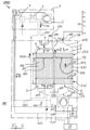
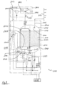
- the adsorption chamber 11 can be formed with a plurality of adsorption channels 101 which contain or have the adsorption material 123 and through which a gas stream can flow such that the gas stream comes into contact with the adsorption material 123 in an effective manner.
- the moisture loading of the adsorption material 123 in the upper area 131 of the adsorption chamber 11 near the first end 111 is also particularly important.
- a portion of the gas stream 45 forms a dried output gas stream 43, which can be fed to its destination by means of an output line 116.
- the pressure increasing device 18 can be designed, for example, with a side channel compressor which is arranged within the drying inlet chamber 8 or in the adsorption container 5.
- the pressure increasing device 18 can be designed with a radial compressor which can have, for example, a ring diffuser.
- the adsorption device 16 can have a control device 14, which serves in particular to control the chamber drive 12 and the pressure increasing device 18.
- the functionality of the control of the adsorption device 16 could, however, also be implemented in a control device 13 of the input compressor 1 or in an external control device 15.
- Corresponding variants are described in the Figure 1 also schematically sketched.
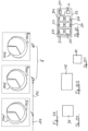
- the sketched control devices 13, 14, 15 are to be understood as examples only and it is understood that in different embodiments one or all of the control devices 13, 14, 15 or a suitable combination of two of these control devices 13, 14, 15 are present and with the components to be controlled and possibly existing measuring and detection devices ME, DE (cf. Figs. 10B, 10A ).
- Each of the control devices 13, 14, 15 can have a computing device RE ( Fig. 10C ), be designed as a component of such a device or be connected to such a device for the purpose of signal/data exchange.
- This loading is determined primarily by the humidity and temperature of the regeneration air that flows through the adsorption material directly before it is turned out of the regeneration area 103. This loading can be reduced by regeneration to a maximum of the equilibrium loading corresponding to the humidity and temperature of the regeneration air.
- the presence of sufficient regeneration conditions can be determined by determining when the rate of increase, i.e. the rate of change over time, of the regeneration inlet temperature falls below a predetermined limit or threshold value.
- the rotation 117 of the adsorption chamber 11 begins depending on whether the regeneration conditions are still improving or are no longer becoming significantly more favorable.
- the measuring device ME and the detection device DE can also be designed together in one component and that instead each of the devices ME, DE can be designed as several separate components, for example to measure several different operating data or time periods or to detect several different events.
- the measuring and detection devices ME, DE can be suitably connected to the computing device RE as required.
- the devices ME, DE, RE or their components can be used as required at any suitable location in the systems 1000, 2000 in order to determine the data required for the operation of the adsorption device explained here, depending on the variant selected.
- the measuring device ME can be designed to measure time periods, temperatures, pressures, gas quantities, gas mass flows or speeds, etc. Any required rates of change can be determined, for example, by means of the computing device RE.
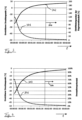
- the desorption potential is indicated as curve 303.
- the desorption potential 303 indicates how much regeneration heat is available for regeneration compared to stationary operation. It can be seen that a large amount of regeneration heat is already available before the adsorption chamber 11 starts. Despite the special feature in the upper area 131 of the adsorption chamber described above, the adsorption material 123 in the regeneration area 103 can already be largely regenerated.
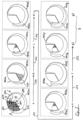
- the loading increases linearly during the residence time of the adsorption material 123 in the working area 102 (drying sector) and decreases linearly during the residence time of the adsorption material 123 in the regeneration area 103 (regeneration sector).
- the lowest possible loading value under the given regeneration conditions i.e. the maximum possible regeneration, is reached after three quarters of the regeneration sector. This is shown graphically by the curve for the loading then hitting the circumference line 133 of the adsorption chamber.
- a loading of exactly zero is not achievable; in the graphic representations of the Figure 5 and in the following explanations, the loading zero shall represent the lowest possible loading due to the respective regeneration conditions.
- the actual course will usually be much more complex.
- the loading of the adsorption material 123 in the flow direction not shown here (essentially normal to the plane of the drawing in Figure 5 , i.e. parallel to the axis of rotation 104) will not be constant.
- the loading curves 401a to 401g can therefore be Figure 5 be understood as the loading averaged over the height H of the adsorption chamber 11. In this way, the sequence of the method according to the first example can be easily illustrated.
- Partial image g2 shows the same state as part of image g1, but in part of image g2 the loading line 401a of the state from part of image a is shown as a reference. It can be seen that the loading 401g in the working area 102 is significantly increased compared to the loading 401a of the stationary state.
- the method according to the first example can be used particularly advantageously when there is an occasional interruption in the compressed air supply.
- the increasing moisture loading of the adsorption material 123 in the working area 102 can be reduced to the loading achieved in the stationary state, corresponding to the loading 401a, in the case of sufficiently long load operating phases 202 by the passage of the adsorption material 123 through the regeneration area 103.
- FIG 8 Shown in Figure 8 four operating states of the adsorption device, namely an operating break 204 (operating state “stop”), a warm-up operating phase 201 (operating state “warm-up”), a load operating phase 202 (operating state “load run”) and a follow-up operating phase 203 (operating state "follow-up”).
- the control device initially switches to a warm-up operating phase 201, as indicated by arrow 241.
- the statements made above for the first exemplary embodiment apply to the warm-up operating phase 201 and the determination of the duration of the warm-up operating phase 201.
- the pressure increase device 18 is already running, while the adsorption chamber 11 is stationary in relation to the working area 102 and the regeneration area 103.
- compressed air is also already being supplied in the warm-up operating phase 201, i.e. the input compressor 1 is in operation.
- the control device triggers a load operating phase 202, see arrow 212. This starts the rotation of the adsorption chamber 11.
- the pressure booster device 18 continues to operate, the input compressor 1 continues to run, and compressed air is pumped.
- the follow-up operating phase 203 is preferably started immediately after the compressed air supply has stopped. This can be advantageous in the case of intermittent operation with short supply breaks, because in this way the probability that compressed air will be requested again before the follow-up operating phase 203 is completed can be reduced.
- a delay in the form of an operating break 204 can also be inserted between the time of the interruption of the compressed air supply and the start of the follow-up operating phase 203, see arrows 224, 243 in Figure 8 , whereby the delay shall preferably last no more than ten minutes, particularly preferably no more than five minutes.
- FIG 11 shows a simplified schematic of an exemplary control device S2 for carrying out the method according to the embodiment with some of its components, whereby it is understood that the control device S2 can have further components.
- the control device S2 has control means S13, S23, S41, S12, S34 and S31, which serve to control the adsorption device in such a way that it Figure 8 with the arrows 213, 223, 241, 212, 234, 231 designated transitions between the operating states 201, 202, 203 and operating breaks 204.
- a heated area of the adsorption chamber 11 with hot adsorption material 123 is moved from the regeneration area 103 through the cooling area 119. If hot adsorption material 123 were to enter the working area 102, it could happen that this material can hardly cool down there - e.g. because of a short operating break 204 - before a warm-up operating phase 201 is triggered again. To prevent hot adsorption material 123 from entering the working area 102 and impairing the drying result there, the cooling gas flow 44 is maintained during the continued rotation.
- the pressure booster device 18 is set to a delivery rate, for example a specific delivery rate per unit of time, during or when the follow-up operating phase 203 is initiated, which is suitable and sufficient for the delivery of the compressed air as a cooling gas flow 44.
- the delivery rate can be regulated by controlling a speed of the pressure booster device 18.
- the adsorption chamber 11 can rotate at a relatively high speed around the follow-up angle, while the delivery rate of the pressure booster device 18 for the follow-up operating phase 203 is reduced compared to the delivery rate in the load operating phase 202 by reducing the speed.
- the speed of the adsorption chamber 11 is preferably selected in stationary operation such that the adsorption material 123 does not absorb more than a defined amount of moisture to be absorbed per pass through the working area 102.
- the "omitted" rotation i.e. the rotation that the adsorption chamber 11 would have performed during normal operation, is determined, in particular calculated, and stored, for example on the storage medium SM of the control device S2. If compressed air is only delivered for a relatively short time, the adsorption chamber 11 is rotated further by the "omitted” rotation after the compressed air delivery has stopped. In this embodiment, the adsorption chamber 11 is then in the position that it would have reached if the adsorption chamber rotation had started at the same time as the compressed air delivery began.
- the caster angle ⁇ is limited to a value of ⁇ ⁇ (2/3) ⁇ . If required, operating phases from further back in time can also be taken into account with their operating data. Required operating data, in particular water concentrations and loads, can be determined if required using the ME measuring device.
- a caster angle ⁇ of zero degrees determined in advance can correspond to a determination that a caster operating phase 203 is not to be initiated and that this can therefore be omitted in the event of an interruption in the conveyance of the gas flow occurring after this load operating phase 202.
- the partial images a" and c" show the partial area moved out of the regeneration area 103 by the associated lag angle ⁇ 0 or ⁇ 1 when the adsorption chamber 11 is rotated further. 550 or 551 of the adsorption material 123.
- the partial area of the adsorption material 123 moved into the regeneration area 103 in the load operating phase 202 between partial images b' and c' is designated by the reference number 510.
- the moisture loading can be increased when the adsorption device 16 is operated according to the method according to the first example, in which Figure 5 illustrated strongly intermittent operation with frequent interruptions and restarts of the compressed air supply are significantly above the preferred loading curve in stationary operation.
- Figure 5 illustrated strongly intermittent operation with frequent interruptions and restarts of the compressed air supply are significantly above the preferred loading curve in stationary operation.
- the adsorption material 123 in the state sequence of the Figure 5 Due to the adsorption chamber downtimes, significantly more compressed air has to be dried during one cycle. However, too high a load in the working area 102 can result in a reduced drying performance of the adsorption material 123.
- the respective size of the sub-areas 410, 510, 550, 551 due to the cylindrical design of the rotatable adsorption chamber 11, if this size is considered as a volume area, depends on the height H of the adsorption chamber 11, its radius R and the angle ⁇ , ⁇ , ⁇ , ⁇ , ⁇ 0 or ⁇ 1 over which the respective sector extends. Since the height H and radius R of the adsorption chamber 11 are constant in the embodiment shown, the angle taken in each case forms a measure of the size of the associated area.
- a control device for controlling the adsorption device 16 can be implemented in the adsorption device 16 itself, as in Figure 1 indicated by the reference number 14.
- a control device for controlling the adsorption device 16 is implemented in an input compressor control device, which is preferably arranged in or on the input compressor 1 and in Figure 1 is provided with the reference number 13.
- a control device of the adsorption device 16 is provided partially or completely as an external control device 15 or interacts with an external central control device 15.
- Each of the control devices 13, 14, 15 can be configured according to the Figure 11 schematically sketched control device S2.
- the axis of rotation 104 of the adsorption chamber 11 can, in a preferred embodiment, Figure 1 shown variant.
- the gas to be dried enters the regeneration area 103 from above, and the gas to be dried enters the working area 102 from below.
- the formulations used above refer to this constellation with regard to the upper and lower areas of the adsorption chamber 11. In general, however, the conditions can be exactly the other way round. A horizontal or other orientation of the axis of rotation 104 of the adsorption chamber 11 is also conceivable. If the gas to be dried enters the regeneration area 103 from below, measures are preferably provided to remove the condensate that accrues during cooling during standstill in an upper area.
Landscapes
- Chemical & Material Sciences (AREA)
- Engineering & Computer Science (AREA)
- Analytical Chemistry (AREA)
- General Chemical & Material Sciences (AREA)
- Oil, Petroleum & Natural Gas (AREA)
- Chemical Kinetics & Catalysis (AREA)
- Separation Of Gases By Adsorption (AREA)
Claims (19)
- Procédé de fonctionnement d'un dispositif d'adsorption (16 ; 2016) destiné à soustraire au moins partiellement un composant adsorbable et/ou condensable d'un flux de gaz (41),dans lequel le dispositif d'adsorption (16 ; 2016) contient une matière d'adsorption (123 ; 2123) et est configuré de manière à ceque la matière d'adsorption (123 ; 2123), dans une zone de travail (102) du dispositif d'adsorption (16; 2016), puisse être mise en contact avec le flux de gaz pour soustraire le composant, etque la matière d'adsorption (123 ; 2123), dans une zone de régénération (103) du dispositif d'adsorption (16 ; 2016), puisse être régénérée par désorption du composant ; etqu'à cet effet, dans une phase de fonctionnement en charge (202) du dispositif d'adsorption (16), des zones partielles (410 ; 510) successives de la matière d'adsorption (123 ; 2123) puissent être déplacées à travers la zone de travail (102) et la zone de régénération (103), en continu de manière répétitive, par rapport à la zone de travail (102) et à la zone de régénération (103),le procédé présentant les étapes de procédé suivantes :- refoulement du flux de gaz (41) à travers le dispositif d'adsorption (16 ; 2016) de manière à ce que le composant soit soustrait au moins en partie du flux de gaz (41) et à ce qu'un flux de gaz de sortie (43), duquel le composant est soustrait au moins en partie, soit fourni ; et- initialisation d'une phase de fonctionnement de poursuite (203) du dispositif d'adsorption (16 ; 2016), pendant laquelle une zone partielle (550, 551) de la matière d'adsorption (123 ; 2123), en raison d'un mouvement par rapport à la zone de régénération (103), est sortie de la zone de régénération (103), avec une interruption au moins temporaire ou l'achèvement du refoulement du flux de gaz (41) pour la fourniture du flux de gaz de sortie (43),caractérisé en ce qu'enplus de la zone de travail (102) et de la zone de régénération (103), une zone de refroidissement (119) est ménagée, et en ce que le dispositif d'adsorption (16 ; 2016) est réalisé de manière à ce que pendant la phase de fonctionnement en charge (202), de la matière d'adsorption (123 ; 2123) régénérée, après le déplacement hors de la zone de régénération (103) et avant une nouvelle entrée dans la zone de travail (102), puisse être refroidie à une température apte à soustraire au moins partiellement le composant du flux de gaz, dans lequel procédé, pendant la phase de fonctionnement de poursuite (203), la zone partielle (550, 551) de la matière d'adsorption (123), sortie de la zone de régénération (203) pendant la phase de fonctionnement de poursuite (203), est rentrée dans la zone de refroidissement (119) en raison d'un mouvement de la matière d'adsorption (123) par rapport à la zone de refroidissement (119) et/ou est passée au moins en partie à travers la zone de refroidissement (119) et y est refroidie, et quele refroidissement pendant la phase de fonctionnement de poursuite (203) est réalisé de manière à ce que pendant la phase de fonctionnement de poursuite (203), un flux de gaz refroidi (44 ; 2044) soit entraîné au moyen d'un dispositif (18 ; 2020) commandable indépendamment du refoulement du flux de gaz (41) pour la fourniture du flux de gaz de sortie (43) , notamment au moyen d'un compresseur ou d'un ventilateur ou d'une pompe ou d'une vanne commandable, le flux de gaz refroidi (44 ; 2044) étant mis en contact avec la matière d'adsorption (123 ; 2123) dans la zone de refroidissement (119) pour le refroidissement de celle-ci.
- Procédé selon la revendication 1, caractérisé en ce que l'initialisation de la phase de fonctionnement de poursuite (203) est réaliséeen fonction de données d'exploitation du dispositif d'adsorption (16 ; 2016), lesquelles sont affectées à une ou à plusieurs phases de fonctionnement (201, 202, 203) et/ou périodes d'arrêt de fonctionnement (204) du dispositif d'adsorption (16 ; 2016), et/ouen fonction de données d'exploitation d'une installation (1000 ; 2000) dans laquelle le dispositif d'adsorption (16 ; 2016) est utilisé, et/ouen fonction d'une durée d'une ou de plusieurs phases de fonctionnement (201, 202, 203) et/ou de périodes d'arrêt de fonctionnement (204) du dispositif d'adsorption (16 ; 2016), et/ouen fonction d'un ou de plusieurs paramètres (β, y, δ) du dispositif d'adsorption (16 ; 2016) et/ou de la matière d'adsorption (123 ; 2123).
- Procédé selon la revendication 1 ou 2, caractérisé en ce que la phase de fonctionnement de poursuite (203) est initialisée directement après l'interruption au moins temporaire ou l'achèvement du refoulement du flux de gaz (41) pour la fourniture du flux de gaz de sortie (43) ou en ce que la phase de fonctionnement de poursuite (203) est initialisée avec un retard entre le moment de l'au moins une interruption au moins temporaire ou de l'achèvement du refoulement du flux de gaz (41) pour la fourniture du flux de gaz de sortie (43) et le moment de l'initialisation de la phase de fonctionnement de poursuite (203), le retard présentant de préférence une durée au plus de dix minutes, de manière particulièrement préférée au plus de cinq minutes.
- Procédé selon l'une quelconque des revendications 1 à 3, caractérisé en ce qu'aucune ou essentiellement aucune régénération de la matière d'adsorption (103) n'a lieu dans la zone de régénération (103) pendant que le refoulement du flux de gaz (41) pour la fourniture du flux de gaz de sortie (43) est interrompu au moins temporairement ou est achevé.
- Procédé selon l'une quelconque des revendications précédentes, caractérisé en ce que le dispositif d'adsorption (16 ; 2016) est configuré de manière à ce que, par rapport à un environnement dans lequel le dispositif d'adsorption (16 ; 2016) est exploité, la zone de travail (102) et la zone de régénération (103) soient ménagées de manière immobile et que la matière d'adsorption (123) soit ménagée de manière déplaçable.
- Procédé selon l'une quelconque des revendications précédentes, caractérisé en ce que pendant le refoulement du flux de gaz (41) pour la fourniture du flux de gaz de sortie (43), le flux de gaz (41) est comprimé par un compresseur d'entrée (1 ; 2001) installé en amont, côté entrée, du dispositif d'adsorption (16 ; 2016).
- Procédé selon l'une quelconque des revendications précédentes, caractérisé en ce que pendant le refoulement du flux de gaz (41) pour la fourniture du flux de gaz de sortie (43), la régénération est réalisée de manière à ce que dans la zone de régénération (103), un flux de gaz de régénération (42) soit mis en contact avec la matière d'adsorption (123 ; 2123).
- Procédé selon la revendication 7, caractérisé en ce que pendant le refoulement du flux de gaz (41) pour la fourniture du flux de gaz de sortie (43), une régénération de flux total de la matière d'adsorption (123) est réalisée et en ce qu'à cet effet, le flux de gaz (41), en tant que flux total, forme le flux de gaz de régénération (42), en ce que le flux de gaz de régénération (42), après une sortie de la zone de régénération (103), est amené à la zone de travail (102) de manière séparée ou combinée à un flux de gaz supplémentaire (44 ; 2044) et y est mis en contact avec la matière d'adsorption (123) pour soustraire le composant au moins partiellement.
- Procédé selon la revendication 7 ou 8, caractérisé en ce que pendant le refoulement du flux de gaz (41) pour la fourniture du flux de gaz de sortie (43), le flux de gaz de régénération (42), après avoir quitté la zone de régénération (103) et avant d'entrer dans la zone de travail (102), est refroidi, seul ou en étant combiné à un flux de gaz supplémentaire (44 ; 2044), au moyen d'un refroidisseur (3), et en ce que le composant est condensé au moins en partie ou est séparé en tant que condensat.
- Procédé selon l'une quelconque des revendications 7 à 9, caractérisé en ce que la pression du flux de gaz de régénération (42), seul ou combiné à un flux de gaz supplémentaire (44 ; 2044), est augmentée au moyen d'un dispositif d'augmentation de pression (18 ; 2018), notamment au moyen d'un compresseur ou d'un ventilateur ou d'une pompe, avant que le flux de gaz de régénération (42) n'arrive dans la zone de travail (102).
- Procédé selon l'une quelconque des revendications précédentes, caractérisé en ce que, lors d'un début ou d'une reprise du refoulement du flux de gaz (41) pour la fourniture du flux de gaz de sortie (43), le dispositif d'adsorption (16) fonctionne d'abord dans une phase de fonctionnement en marche à chaud (201) pendant que le flux de gaz (41) pour la fourniture du flux de gaz de sortie (43) est refoulé, et en ce que la matière d'adsorption (123 ; 2123) est immobile par rapport à la zone de travail (102) et à la zone de régénération (103).
- Procédé selon la revendication 11, caractérisé en ce qu' après la phase de fonctionnement à chaud (201), une phase de fonctionnement en charge (202) est initialisée pendant que les zones partielles (410 ; 510) successives de la matière d'adsorption (123 ; 2123) sont déplacées à travers la zone de travail (102) et la zone de régénération (103), en continu de manière répétitive, par rapport à la zone de travail (102) et à la zone de régénération (103).
- Procédé selon la revendication 12, caractérisé en ce que la durée de la phase de fonctionnement en marche à chaud (201), prise du début ou de la reprise du refoulement du flux de gaz (41) pour la fourniture du flux de gaz de sortie (43) jusqu'à l'initialisation de la phase de fonctionnement en charge (202), est variable.
- Procédé selon la revendication 12 ou 13, caractérisé en ce que la durée de la phase de fonctionnement en marche à chaud (201), prise du début ou de la reprise du refoulement du flux de gaz (41) pour la fourniture du flux de gaz de sortie (43) jusqu'à l'initialisation de la phase de fonctionnement en charge (202) (202), est déterminéeen tenant compte de données d'exploitation du dispositif d'adsorption (16 ; 2016), lesquelles sont affectées à une phase de fonctionnement en cours (201 - 203) et/ou à une phase de fonctionnement précédente (201 - 203) et/ou à une période d'arrêt de fonctionnement (204) ou à plusieurs phases de fonctionnement précédentes (201 - 203) et/ou périodes d'arrêt de fonctionnement du dispositif d'adsorption (16 ; 2016), et/ouen tenant compte de données d'exploitation d'une installation (1000 ; 2000) dans laquelle le dispositif d'adsorption (16 ; 2016) est utilisé, et/ouen tenant compte d'une durée d'une ou de plusieurs phases de fonctionnement précédentes (201 - 203) et/ou de périodes d'arrêt de fonctionnement (204) du dispositif d'adsorption (16 ; 2016), et/ouen tenant compte d'un ou de plusieurs paramètres (β, γ, δ) du dispositif d'adsorption (16 ; 2016) et/ou de la matière d'adsorption (123 ; 2123).
- Procédé selon la revendication 1 en relation avec la revendication 10, caractérisé en ce que le dispositif d'augmentation de pression (18) forme le dispositif commandable, et en ce que le flux de gaz refroidi (44) est entraîné pendant la phase de fonctionnement de poursuite (2013) au moyen du dispositif d'augmentation de pression (18), un débit du dispositif d'augmentation de pression (18), lors de l'initialisation de la phase de fonctionnement de poursuite (203) ou pendant la phase de fonctionnement de poursuite (203), étant réglé sur une mesure apte à entraîner un flux de gaz refroidi (44) suffisant, notamment étant diminué par rapport au débit pendant la phase de fonctionnement en charge (202) précédente.
- Procédé selon l'une quelconque des revendications précédentes, caractérisé en ce qu'une grandeur (θ0, θ1) de la zone partielle (550, 551) de la matière d'adsorption (123 ; 2123), sortie de la zone de régénération (103) pendant la phase de fonctionnement de poursuite (203), n'est pas plus de deux tiers d'une grandeur (β) de la zone de régénération (103).
- Procédé selon l'une quelconque des revendications précédentes, caractérisé en ce qu'une durée de la phase de fonctionnement de poursuite (203) et/ou une grandeur (θ0, θ1) de la zone partielle (550, 551) de la matière d'adsorption (123 ; 2123), sortie de la zone de régénération (103) pendant la phase de fonctionnement de poursuite (203), sont réglées de manière fixe ou sont déterminéesen fonction de données d'exploitation du dispositif d'adsorption (16 ; 2016), lesquelles sont affectées à une ou à plusieurs phases de fonctionnement (201 - 203) et/ou périodes d'arrêt de fonctionnement (204) du dispositif d'adsorption (16 ; 2016), et/ouen fonction de données d'exploitation d'une installation (1000 ; 2000) dans laquelle le dispositif d'adsorption (16 ; 2016) est utilisé, et/ouen fonction de la durée d'une ou de plusieurs phases de fonctionnement (201 - 203) et/ou de périodes d'arrêt de fonctionnement (204) du dispositif d'adsorption (16 ; 2016), et/ouen fonction d'un ou de plusieurs paramètres prédéterminés (β, γ, δ) du dispositif d'adsorption (16 ; 2016) et/ou de la matière d'adsorption (123 ; 2123).
- Procédé selon l'une quelconque des revendications précédentes en relation avec la revendication 11, caractérisé en ce que lors de la détermination d'une durée de la phase de fonctionnement de poursuite (203) et/ou d'une grandeur (80, 81) de la zone partielle (550, 551) de la matière d'adsorption (123 ; 2123), à sortir de la zone de régénération (103) pendant la phase de fonctionnement de poursuite (203), une mesure pour le mouvement que la matière d'adsorption (123 ; 2123) aurait exécuté pendant la durée de la phase de fonctionnement à chaud (201), notamment de la dernière phase de fonctionnement à chaud (201) précédant la phase de fonctionnement de poursuite (203), par rapport à la zone de travail (102) et à la zone de régénération (103), si le dispositif d'adsorption (16 ; 2016) avait été exploité pendant une phase de fonctionnement en charge (202) au lieu de la phase de fonctionnement à chaud (201), est prise en compte.
- Dispositif de commande (S2) qui est réalisé pour commander un dispositif d'adsorption (16 ; 2016) destiné à soustraire au moins partiellement un composant adsorbable et/ou condensable d'un flux de gaz (41) pour un fonctionnement suivant un procédé selon l'une quelconque des revendications 1 à 18,le dispositif d'adsorption (16 ; 2016) à commander contenant une matière d'adsorption (123 ; 2123) et étant configuré de manière à ce queque la matière d'adsorption (123 ; 2123), dans une zone de travail (102) du dispositif d'adsorption (16; 2016), puisse être mise en contact avec le flux de gaz pour soustraire le composant, etque la matière d'adsorption (123 ; 2123), dans une zone de régénération (103) du dispositif d'adsorption (16 ; 2016), puisse être régénérée par désorption du composant ; etqu'à cet effet, pendant une phase de fonctionnement en charge (202) du dispositif d'adsorption (16), des zones partielles (410 ; 510) successives de la matière d'adsorption (123 ; 2123) puissent être déplacées à travers la zone de travail (102) et la zone de régénération (103), en continu de manière répétitive, par rapport à la zone de travail (102) et à la zone de régénération (103 ;le dispositif de commande (S2) présentant des moyens de commande (S23, S13)destinés à initialiser une phase de fonctionnement de poursuite (203) du dispositif d'adsorption (16 ; 2016) et destinés à commander le dispositif d'adsorption (16 ; 2016) de manière à ce que pendant la phase de fonctionnement de poursuite (203), une zone partielle (550, 551) de la matière d'adsorption (123 ; 2123) soit sortie de la zone de régénération (103) en raison d'un mouvement par rapport à la zone de régénération (103) lorsqu'un refoulement du flux de gaz (41) à travers le dispositif d'adsorption (16 ; 2016) est interrompu au moins temporairement ou est achevé, de manière à ce que le composant soit soustrait au moins en partie du flux de gaz (41) et qu'un flux de gaz de sortie (43) soit fourni, duquel le composant est au moins soustrait.
Priority Applications (4)
| Application Number | Priority Date | Filing Date | Title |
|---|---|---|---|
| EP13183511.8A EP2845638B2 (fr) | 2013-09-09 | 2013-09-09 | Procédé de fonctionnement d'un dispositif d'adsorption et dispositif de commande |
| PCT/EP2014/068845 WO2015032862A2 (fr) | 2013-09-09 | 2014-09-04 | Procédé permettant de faire fonctionner un dispositif d'adsorption et dispositif de commande |
| MX2016003060A MX365757B (es) | 2013-09-09 | 2014-09-04 | Metodos para operar un dispositivo de adsorcion y una unidad de control. |
| US14/917,700 US9943803B2 (en) | 2013-09-09 | 2014-09-04 | Method for operating an adsorption device and a control unit |
Applications Claiming Priority (1)
| Application Number | Priority Date | Filing Date | Title |
|---|---|---|---|
| EP13183511.8A EP2845638B2 (fr) | 2013-09-09 | 2013-09-09 | Procédé de fonctionnement d'un dispositif d'adsorption et dispositif de commande |
Publications (3)
| Publication Number | Publication Date |
|---|---|
| EP2845638A1 EP2845638A1 (fr) | 2015-03-11 |
| EP2845638B1 EP2845638B1 (fr) | 2018-08-22 |
| EP2845638B2 true EP2845638B2 (fr) | 2024-07-03 |
Family
ID=49150785
Family Applications (1)
| Application Number | Title | Priority Date | Filing Date |
|---|---|---|---|
| EP13183511.8A Active EP2845638B2 (fr) | 2013-09-09 | 2013-09-09 | Procédé de fonctionnement d'un dispositif d'adsorption et dispositif de commande |
Country Status (4)
| Country | Link |
|---|---|
| US (1) | US9943803B2 (fr) |
| EP (1) | EP2845638B2 (fr) |
| MX (1) | MX365757B (fr) |
| WO (1) | WO2015032862A2 (fr) |
Families Citing this family (6)
| Publication number | Priority date | Publication date | Assignee | Title |
|---|---|---|---|---|
| US10695711B2 (en) * | 2017-04-28 | 2020-06-30 | Uop Llc | Remote monitoring of adsorber process units |
| CN110772927B (zh) | 2019-06-28 | 2021-01-29 | 上海深城环保设备工程有限公司 | 并列管式气体吸附浓集装置 |
| ES2968178T3 (es) * | 2019-08-16 | 2024-05-08 | Atlas Copco Airpower Nv | Secador para gas comprimido, instalación de compresor provista de un secador y un método para secar gas comprimido |
| BE1027504B1 (nl) * | 2019-08-16 | 2021-03-15 | Atlas Copco Airpower Nv | Droger voor samengeperst gas, compressorinstallatie voorzien van droger en werkwijze voor het drogen van samengeperst gas |
| CN113340765B (zh) * | 2021-06-25 | 2023-06-27 | 西藏大学 | 一种分子筛材料吸附性能检测装置及方法 |
| CN116371144B (zh) * | 2023-04-10 | 2024-01-05 | 苏州市环境保护有限公司 | 沸石转轮设备在治理喷涂废气中的处理方法 |
Citations (3)
| Publication number | Priority date | Publication date | Assignee | Title |
|---|---|---|---|---|
| WO2002047797A1 (fr) † | 2000-12-11 | 2002-06-20 | Questair Technologies, Inc. | Amp avec adsorbants sensibles aux contaminants |
| US7569095B2 (en) † | 2004-08-04 | 2009-08-04 | Atlas Copco Airpower, Naamloze Vennootschap | Method for drying a gas and device applied thereby |
| US20110132191A1 (en) † | 2009-12-03 | 2011-06-09 | Kaeser Kompressoren Gmbh | Adsorption drying apparatus and adsorption drying method |
Family Cites Families (13)
| Publication number | Priority date | Publication date | Assignee | Title |
|---|---|---|---|---|
| BE1005764A3 (nl) | 1992-04-15 | 1994-01-18 | Atlas Copco Airpower Nv | Inrichting voor het drogen van een gas. |
| CH691349A5 (de) * | 1995-03-16 | 2001-07-13 | Gunnar Ankarstig | Verfahren und Vorrichtung zum Trocknen von Luft. |
| EP0805010B1 (fr) | 1996-05-03 | 2001-10-31 | Roderich Wilhelm Dr.-Ing. Gräff | Procédé et appareil pour régénérer un adsorbant |
| WO2000074819A1 (fr) | 1999-06-04 | 2000-12-14 | Flair Corporation | Systeme et procede d'adsorbeur a tambour rotatif |
| JP2001141274A (ja) | 1999-11-12 | 2001-05-25 | Daikin Ind Ltd | クリーンルーム |
| US7326277B1 (en) | 2004-04-14 | 2008-02-05 | Uop Llc | Brake air drying using low pressure desiccant wheel |
| BE1016939A3 (nl) | 2006-01-12 | 2007-10-02 | Atlas Copco Airpower Nv | Verbeterde werkwijze voor het drogen van een gas en inrichting daarbij toegepast. |
| US7601206B2 (en) * | 2006-08-22 | 2009-10-13 | Mesosystems Technology, Inc. | Method and apparatus for generating water using an energy conversion device |
| US8328904B2 (en) | 2009-05-04 | 2012-12-11 | Bry-Air, Inc. | Method and system for control of desiccant dehumidifier |
| BE1018854A3 (nl) | 2009-08-11 | 2011-10-04 | Atlas Copco Airpower Nv | Droger voor samengeperst gas en werkwijze daarbij toegepast. |
| AT509475B1 (de) * | 2010-03-03 | 2012-01-15 | Wittmann Kunststoffgeraete | Verfahren zum trocknen von schüttgut |
| US20120145000A1 (en) | 2010-12-10 | 2012-06-14 | L'air Liquide Societe Anonyme Pour L'etude Et L'exploitation Des Procedes Georges Claude | Drying Process For Flue Gas Treatment |
| US8641804B2 (en) | 2011-07-29 | 2014-02-04 | Hewlett-Packard Development Company, L.P. | Systems and methods to condition air |
-
2013
- 2013-09-09 EP EP13183511.8A patent/EP2845638B2/fr active Active
-
2014
- 2014-09-04 WO PCT/EP2014/068845 patent/WO2015032862A2/fr not_active Ceased
- 2014-09-04 US US14/917,700 patent/US9943803B2/en active Active
- 2014-09-04 MX MX2016003060A patent/MX365757B/es active IP Right Grant
Patent Citations (3)
| Publication number | Priority date | Publication date | Assignee | Title |
|---|---|---|---|---|
| WO2002047797A1 (fr) † | 2000-12-11 | 2002-06-20 | Questair Technologies, Inc. | Amp avec adsorbants sensibles aux contaminants |
| US7569095B2 (en) † | 2004-08-04 | 2009-08-04 | Atlas Copco Airpower, Naamloze Vennootschap | Method for drying a gas and device applied thereby |
| US20110132191A1 (en) † | 2009-12-03 | 2011-06-09 | Kaeser Kompressoren Gmbh | Adsorption drying apparatus and adsorption drying method |
Also Published As
| Publication number | Publication date |
|---|---|
| EP2845638A1 (fr) | 2015-03-11 |
| MX365757B (es) | 2019-06-12 |
| US9943803B2 (en) | 2018-04-17 |
| US20160214056A1 (en) | 2016-07-28 |
| EP2845638B1 (fr) | 2018-08-22 |
| WO2015032862A2 (fr) | 2015-03-12 |
| WO2015032862A3 (fr) | 2015-05-07 |
| MX2016003060A (es) | 2016-09-28 |
Similar Documents
| Publication | Publication Date | Title |
|---|---|---|
| EP2845638B2 (fr) | Procédé de fonctionnement d'un dispositif d'adsorption et dispositif de commande | |
| EP2582560B1 (fr) | Dispositif, procédé et système de commande pneumatique et d'alimentation pneumatique | |
| EP1926400B1 (fr) | Procede et dispositif pour creer une atmosphere conditionnee | |
| EP2587203B1 (fr) | Séchoir à bande | |
| EP2542847B1 (fr) | Procédé et dispositif de séchage de produits en vrac | |
| EP2051794A1 (fr) | Équipement pour produire un gaz utile enrichi par un composant prédéfini | |
| CH626155A5 (fr) | ||
| EP1385601A2 (fr) | Procede de regeneration d'air de traitement charge d'humidite et ensemble pour la mise en oeuvre dudit procede | |
| EP3020972B1 (fr) | Derivation de dispositif de refroidissement auxiliaire | |
| WO2008119608A2 (fr) | Séchoir hybride et procédé d'exploitation d'un séchoir hybride de ce type | |
| EP0760455A2 (fr) | Dispositif avec au moins un récipient de stockage pour matériau à traiter, en particulier de granules en matière plastique | |
| EP3439765B1 (fr) | Dispositif et procédé d'épuration d'air | |
| DE102007013092A1 (de) | Vorrichtung und Verfahren zum Trocknen von in geschlossenen Kreisläufen geführten Fluiden | |
| EP3405673B1 (fr) | Procédé de détection d'une soupape bloquée d'un compresseur de réfrigerant et système de commande pour un compresseur de réfrigerant | |
| DE102019109379B4 (de) | Verfahren zum Klimatisieren eines Fahrzeuginnenraums mit großem Volumen und hierfür eingerichtete Klimaanlage | |
| DE1503423A1 (de) | Verfahren und Vorrichtung zur Herstellung trockener Druckluft | |
| WO2024200590A1 (fr) | Séchoir à adsorption | |
| EP2626125A1 (fr) | Dispositif de séchage et de filtration d'un gaz | |
| EP1923649A2 (fr) | Procédé pour le séchage d'une matière à sécher ainsi qu'une installation pour la mise en oeuvre du procédé | |
| EP3000676B1 (fr) | Procede de fonctionnement d'un systeme d'air comprime d'un vehicule | |
| DE10355927A1 (de) | Verfahren mit Kombinationstrockner zur Aufbereitung von Druckluft und Gasen | |
| DE102008031747A1 (de) | Vorrichtung zum Bereitstellen von aufbereiteter Luft zur Verwendung als Druckluft in einem pneumatisch betriebenen Bremssystem eines Fahrzeuges | |
| DE102014019805B3 (de) | Kompressoranlage zur Komprimierung von Gasen | |
| WO2013124140A1 (fr) | Séchage de produits alimentaires, notamment de pâtes | |
| EP3461551A1 (fr) | Dispositif de traitement de l'air et procédé à fonction améliorée |
Legal Events
| Date | Code | Title | Description |
|---|---|---|---|
| 17P | Request for examination filed |
Effective date: 20140904 |
|
| AK | Designated contracting states |
Kind code of ref document: A1 Designated state(s): AL AT BE BG CH CY CZ DE DK EE ES FI FR GB GR HR HU IE IS IT LI LT LU LV MC MK MT NL NO PL PT RO RS SE SI SK SM TR |
|
| AX | Request for extension of the european patent |
Extension state: BA ME |
|
| PUAI | Public reference made under article 153(3) epc to a published international application that has entered the european phase |
Free format text: ORIGINAL CODE: 0009012 |
|
| GRAP | Despatch of communication of intention to grant a patent |
Free format text: ORIGINAL CODE: EPIDOSNIGR1 |
|
| STAA | Information on the status of an ep patent application or granted ep patent |
Free format text: STATUS: GRANT OF PATENT IS INTENDED |
|
| INTG | Intention to grant announced |
Effective date: 20180509 |
|
| GRAS | Grant fee paid |
Free format text: ORIGINAL CODE: EPIDOSNIGR3 |
|
| GRAA | (expected) grant |
Free format text: ORIGINAL CODE: 0009210 |
|
| STAA | Information on the status of an ep patent application or granted ep patent |
Free format text: STATUS: THE PATENT HAS BEEN GRANTED |
|
| AK | Designated contracting states |
Kind code of ref document: B1 Designated state(s): AL AT BE BG CH CY CZ DE DK EE ES FI FR GB GR HR HU IE IS IT LI LT LU LV MC MK MT NL NO PL PT RO RS SE SI SK SM TR |
|
| REG | Reference to a national code |
Ref country code: GB Ref legal event code: FG4D Free format text: NOT ENGLISH |
|
| REG | Reference to a national code |
Ref country code: CH Ref legal event code: EP |
|
| REG | Reference to a national code |
Ref country code: AT Ref legal event code: REF Ref document number: 1031805 Country of ref document: AT Kind code of ref document: T Effective date: 20180915 |
|
| REG | Reference to a national code |
Ref country code: IE Ref legal event code: FG4D Free format text: LANGUAGE OF EP DOCUMENT: GERMAN |
|
| REG | Reference to a national code |
Ref country code: DE Ref legal event code: R096 Ref document number: 502013010910 Country of ref document: DE |
|
| REG | Reference to a national code |
Ref country code: FR Ref legal event code: PLFP Year of fee payment: 6 |
|
| REG | Reference to a national code |
Ref country code: NL Ref legal event code: FP |
|
| REG | Reference to a national code |
Ref country code: LT Ref legal event code: MG4D |
|
| PG25 | Lapsed in a contracting state [announced via postgrant information from national office to epo] |
Ref country code: FI Free format text: LAPSE BECAUSE OF FAILURE TO SUBMIT A TRANSLATION OF THE DESCRIPTION OR TO PAY THE FEE WITHIN THE PRESCRIBED TIME-LIMIT Effective date: 20180822 Ref country code: NO Free format text: LAPSE BECAUSE OF FAILURE TO SUBMIT A TRANSLATION OF THE DESCRIPTION OR TO PAY THE FEE WITHIN THE PRESCRIBED TIME-LIMIT Effective date: 20181122 Ref country code: GR Free format text: LAPSE BECAUSE OF FAILURE TO SUBMIT A TRANSLATION OF THE DESCRIPTION OR TO PAY THE FEE WITHIN THE PRESCRIBED TIME-LIMIT Effective date: 20181123 Ref country code: RS Free format text: LAPSE BECAUSE OF FAILURE TO SUBMIT A TRANSLATION OF THE DESCRIPTION OR TO PAY THE FEE WITHIN THE PRESCRIBED TIME-LIMIT Effective date: 20180822 Ref country code: IS Free format text: LAPSE BECAUSE OF FAILURE TO SUBMIT A TRANSLATION OF THE DESCRIPTION OR TO PAY THE FEE WITHIN THE PRESCRIBED TIME-LIMIT Effective date: 20181222 Ref country code: LT Free format text: LAPSE BECAUSE OF FAILURE TO SUBMIT A TRANSLATION OF THE DESCRIPTION OR TO PAY THE FEE WITHIN THE PRESCRIBED TIME-LIMIT Effective date: 20180822 Ref country code: BG Free format text: LAPSE BECAUSE OF FAILURE TO SUBMIT A TRANSLATION OF THE DESCRIPTION OR TO PAY THE FEE WITHIN THE PRESCRIBED TIME-LIMIT Effective date: 20181122 Ref country code: SE Free format text: LAPSE BECAUSE OF FAILURE TO SUBMIT A TRANSLATION OF THE DESCRIPTION OR TO PAY THE FEE WITHIN THE PRESCRIBED TIME-LIMIT Effective date: 20180822 |
|
| PG25 | Lapsed in a contracting state [announced via postgrant information from national office to epo] |
Ref country code: AL Free format text: LAPSE BECAUSE OF FAILURE TO SUBMIT A TRANSLATION OF THE DESCRIPTION OR TO PAY THE FEE WITHIN THE PRESCRIBED TIME-LIMIT Effective date: 20180822 Ref country code: HR Free format text: LAPSE BECAUSE OF FAILURE TO SUBMIT A TRANSLATION OF THE DESCRIPTION OR TO PAY THE FEE WITHIN THE PRESCRIBED TIME-LIMIT Effective date: 20180822 Ref country code: LV Free format text: LAPSE BECAUSE OF FAILURE TO SUBMIT A TRANSLATION OF THE DESCRIPTION OR TO PAY THE FEE WITHIN THE PRESCRIBED TIME-LIMIT Effective date: 20180822 |
|
| PG25 | Lapsed in a contracting state [announced via postgrant information from national office to epo] |
Ref country code: ES Free format text: LAPSE BECAUSE OF FAILURE TO SUBMIT A TRANSLATION OF THE DESCRIPTION OR TO PAY THE FEE WITHIN THE PRESCRIBED TIME-LIMIT Effective date: 20180822 Ref country code: PL Free format text: LAPSE BECAUSE OF FAILURE TO SUBMIT A TRANSLATION OF THE DESCRIPTION OR TO PAY THE FEE WITHIN THE PRESCRIBED TIME-LIMIT Effective date: 20180822 Ref country code: RO Free format text: LAPSE BECAUSE OF FAILURE TO SUBMIT A TRANSLATION OF THE DESCRIPTION OR TO PAY THE FEE WITHIN THE PRESCRIBED TIME-LIMIT Effective date: 20180822 Ref country code: CZ Free format text: LAPSE BECAUSE OF FAILURE TO SUBMIT A TRANSLATION OF THE DESCRIPTION OR TO PAY THE FEE WITHIN THE PRESCRIBED TIME-LIMIT Effective date: 20180822 Ref country code: EE Free format text: LAPSE BECAUSE OF FAILURE TO SUBMIT A TRANSLATION OF THE DESCRIPTION OR TO PAY THE FEE WITHIN THE PRESCRIBED TIME-LIMIT Effective date: 20180822 |
|
| REG | Reference to a national code |
Ref country code: CH Ref legal event code: PL |
|
| REG | Reference to a national code |
Ref country code: DE Ref legal event code: R026 Ref document number: 502013010910 Country of ref document: DE |
|
| PLBI | Opposition filed |
Free format text: ORIGINAL CODE: 0009260 |
|
| PG25 | Lapsed in a contracting state [announced via postgrant information from national office to epo] |
Ref country code: SM Free format text: LAPSE BECAUSE OF FAILURE TO SUBMIT A TRANSLATION OF THE DESCRIPTION OR TO PAY THE FEE WITHIN THE PRESCRIBED TIME-LIMIT Effective date: 20180822 Ref country code: DK Free format text: LAPSE BECAUSE OF FAILURE TO SUBMIT A TRANSLATION OF THE DESCRIPTION OR TO PAY THE FEE WITHIN THE PRESCRIBED TIME-LIMIT Effective date: 20180822 Ref country code: SK Free format text: LAPSE BECAUSE OF FAILURE TO SUBMIT A TRANSLATION OF THE DESCRIPTION OR TO PAY THE FEE WITHIN THE PRESCRIBED TIME-LIMIT Effective date: 20180822 |
|
| PLAX | Notice of opposition and request to file observation + time limit sent |
Free format text: ORIGINAL CODE: EPIDOSNOBS2 |
|
| 26 | Opposition filed |
Opponent name: ATLAS COPCO AIRPOWER N.V. Effective date: 20190522 |
|
| REG | Reference to a national code |
Ref country code: IE Ref legal event code: MM4A |
|
| PG25 | Lapsed in a contracting state [announced via postgrant information from national office to epo] |
Ref country code: MC Free format text: LAPSE BECAUSE OF FAILURE TO SUBMIT A TRANSLATION OF THE DESCRIPTION OR TO PAY THE FEE WITHIN THE PRESCRIBED TIME-LIMIT Effective date: 20180822 Ref country code: LU Free format text: LAPSE BECAUSE OF NON-PAYMENT OF DUE FEES Effective date: 20180909 |
|
| PG25 | Lapsed in a contracting state [announced via postgrant information from national office to epo] |
Ref country code: IE Free format text: LAPSE BECAUSE OF NON-PAYMENT OF DUE FEES Effective date: 20180909 |
|
| PG25 | Lapsed in a contracting state [announced via postgrant information from national office to epo] |
Ref country code: SI Free format text: LAPSE BECAUSE OF FAILURE TO SUBMIT A TRANSLATION OF THE DESCRIPTION OR TO PAY THE FEE WITHIN THE PRESCRIBED TIME-LIMIT Effective date: 20180822 Ref country code: LI Free format text: LAPSE BECAUSE OF NON-PAYMENT OF DUE FEES Effective date: 20180930 Ref country code: CH Free format text: LAPSE BECAUSE OF NON-PAYMENT OF DUE FEES Effective date: 20180930 |
|
| PLBB | Reply of patent proprietor to notice(s) of opposition received |
Free format text: ORIGINAL CODE: EPIDOSNOBS3 |
|
| PG25 | Lapsed in a contracting state [announced via postgrant information from national office to epo] |
Ref country code: MT Free format text: LAPSE BECAUSE OF FAILURE TO SUBMIT A TRANSLATION OF THE DESCRIPTION OR TO PAY THE FEE WITHIN THE PRESCRIBED TIME-LIMIT Effective date: 20180822 |
|
| PG25 | Lapsed in a contracting state [announced via postgrant information from national office to epo] |
Ref country code: TR Free format text: LAPSE BECAUSE OF FAILURE TO SUBMIT A TRANSLATION OF THE DESCRIPTION OR TO PAY THE FEE WITHIN THE PRESCRIBED TIME-LIMIT Effective date: 20180822 |
|
| PG25 | Lapsed in a contracting state [announced via postgrant information from national office to epo] |
Ref country code: PT Free format text: LAPSE BECAUSE OF FAILURE TO SUBMIT A TRANSLATION OF THE DESCRIPTION OR TO PAY THE FEE WITHIN THE PRESCRIBED TIME-LIMIT Effective date: 20180822 Ref country code: HU Free format text: LAPSE BECAUSE OF FAILURE TO SUBMIT A TRANSLATION OF THE DESCRIPTION OR TO PAY THE FEE WITHIN THE PRESCRIBED TIME-LIMIT; INVALID AB INITIO Effective date: 20130909 |
|
| PG25 | Lapsed in a contracting state [announced via postgrant information from national office to epo] |
Ref country code: CY Free format text: LAPSE BECAUSE OF FAILURE TO SUBMIT A TRANSLATION OF THE DESCRIPTION OR TO PAY THE FEE WITHIN THE PRESCRIBED TIME-LIMIT Effective date: 20180822 Ref country code: MK Free format text: LAPSE BECAUSE OF NON-PAYMENT OF DUE FEES Effective date: 20180822 |
|
| APAH | Appeal reference modified |
Free format text: ORIGINAL CODE: EPIDOSCREFNO |
|
| APBM | Appeal reference recorded |
Free format text: ORIGINAL CODE: EPIDOSNREFNO |
|
| APBP | Date of receipt of notice of appeal recorded |
Free format text: ORIGINAL CODE: EPIDOSNNOA2O |
|
| APBQ | Date of receipt of statement of grounds of appeal recorded |
Free format text: ORIGINAL CODE: EPIDOSNNOA3O |
|
| P01 | Opt-out of the competence of the unified patent court (upc) registered |
Effective date: 20230412 |
|
| APBU | Appeal procedure closed |
Free format text: ORIGINAL CODE: EPIDOSNNOA9O |
|
| REG | Reference to a national code |
Ref country code: DE Ref legal event code: R082 Ref document number: 502013010910 Country of ref document: DE Representative=s name: EISENFUEHR SPEISER PATENTANWAELTE RECHTSANWAEL, DE |
|
| PUAH | Patent maintained in amended form |
Free format text: ORIGINAL CODE: 0009272 |
|
| STAA | Information on the status of an ep patent application or granted ep patent |
Free format text: STATUS: PATENT MAINTAINED AS AMENDED |
|
| 27A | Patent maintained in amended form |
Effective date: 20240703 |
|
| AK | Designated contracting states |
Kind code of ref document: B2 Designated state(s): AL AT BE BG CH CY CZ DE DK EE ES FI FR GB GR HR HU IE IS IT LI LT LU LV MC MK MT NL NO PL PT RO RS SE SI SK SM TR |
|
| REG | Reference to a national code |
Ref country code: DE Ref legal event code: R102 Ref document number: 502013010910 Country of ref document: DE |
|
| REG | Reference to a national code |
Ref country code: NL Ref legal event code: FP |
|
| PGFP | Annual fee paid to national office [announced via postgrant information from national office to epo] |
Ref country code: NL Payment date: 20250922 Year of fee payment: 13 |
|
| PGFP | Annual fee paid to national office [announced via postgrant information from national office to epo] |
Ref country code: BE Payment date: 20250919 Year of fee payment: 13 Ref country code: GB Payment date: 20250923 Year of fee payment: 13 |
|
| PGFP | Annual fee paid to national office [announced via postgrant information from national office to epo] |
Ref country code: FR Payment date: 20250922 Year of fee payment: 13 Ref country code: AT Payment date: 20250918 Year of fee payment: 13 |
|
| PGFP | Annual fee paid to national office [announced via postgrant information from national office to epo] |
Ref country code: DE Payment date: 20251007 Year of fee payment: 13 |
|
| PGFP | Annual fee paid to national office [announced via postgrant information from national office to epo] |
Ref country code: IT Payment date: 20250930 Year of fee payment: 13 |