EP2845640A1 - Unité de procédé multi-fonction pour la réduction de la concentration en polluants dans un effluent gazeux - Google Patents
Unité de procédé multi-fonction pour la réduction de la concentration en polluants dans un effluent gazeux Download PDFInfo
- Publication number
- EP2845640A1 EP2845640A1 EP13466019.0A EP13466019A EP2845640A1 EP 2845640 A1 EP2845640 A1 EP 2845640A1 EP 13466019 A EP13466019 A EP 13466019A EP 2845640 A1 EP2845640 A1 EP 2845640A1
- Authority
- EP
- European Patent Office
- Prior art keywords
- reactor
- built
- operation unit
- portions
- catalyst
- Prior art date
- Legal status (The legal status is an assumption and is not a legal conclusion. Google has not performed a legal analysis and makes no representation as to the accuracy of the status listed.)
- Granted
Links
- 239000002912 waste gas Substances 0.000 title claims abstract description 19
- 239000003344 environmental pollutant Substances 0.000 title claims abstract description 11
- 231100000719 pollutant Toxicity 0.000 title claims abstract description 11
- 230000003197 catalytic effect Effects 0.000 claims abstract description 33
- 239000003546 flue gas Substances 0.000 claims abstract description 25
- 238000001816 cooling Methods 0.000 claims abstract description 9
- 238000009413 insulation Methods 0.000 claims abstract description 5
- 239000003054 catalyst Substances 0.000 claims description 40
- UGFAIRIUMAVXCW-UHFFFAOYSA-N Carbon monoxide Chemical compound [O+]#[C-] UGFAIRIUMAVXCW-UHFFFAOYSA-N 0.000 claims description 9
- 239000007789 gas Substances 0.000 claims description 9
- IJGRMHOSHXDMSA-UHFFFAOYSA-N Atomic nitrogen Chemical compound N#N IJGRMHOSHXDMSA-UHFFFAOYSA-N 0.000 claims description 6
- 239000000203 mixture Substances 0.000 claims description 5
- 239000011796 hollow space material Substances 0.000 claims description 4
- 238000000265 homogenisation Methods 0.000 claims description 4
- 239000000463 material Substances 0.000 claims description 3
- 229910052757 nitrogen Inorganic materials 0.000 claims description 3
- 239000012798 spherical particle Substances 0.000 claims description 3
- 239000002245 particle Substances 0.000 claims description 2
- 238000000034 method Methods 0.000 description 13
- 238000005516 engineering process Methods 0.000 description 12
- 239000012855 volatile organic compound Substances 0.000 description 12
- 230000003647 oxidation Effects 0.000 description 10
- 238000007254 oxidation reaction Methods 0.000 description 10
- 238000012360 testing method Methods 0.000 description 10
- 230000008569 process Effects 0.000 description 6
- 238000000746 purification Methods 0.000 description 5
- 230000007704 transition Effects 0.000 description 5
- 238000002485 combustion reaction Methods 0.000 description 4
- 238000007084 catalytic combustion reaction Methods 0.000 description 3
- 238000006243 chemical reaction Methods 0.000 description 3
- 239000003517 fume Substances 0.000 description 3
- MWUXSHHQAYIFBG-UHFFFAOYSA-N nitrogen oxide Inorganic materials O=[N] MWUXSHHQAYIFBG-UHFFFAOYSA-N 0.000 description 3
- 238000001833 catalytic reforming Methods 0.000 description 2
- 230000000694 effects Effects 0.000 description 2
- 230000008030 elimination Effects 0.000 description 2
- 238000003379 elimination reaction Methods 0.000 description 2
- 230000007774 longterm Effects 0.000 description 2
- 230000001105 regulatory effect Effects 0.000 description 2
- 239000000126 substance Substances 0.000 description 2
- 230000002411 adverse Effects 0.000 description 1
- 238000003915 air pollution Methods 0.000 description 1
- 230000015572 biosynthetic process Effects 0.000 description 1
- 238000004523 catalytic cracking Methods 0.000 description 1
- 238000006555 catalytic reaction Methods 0.000 description 1
- 238000010531 catalytic reduction reaction Methods 0.000 description 1
- 238000000354 decomposition reaction Methods 0.000 description 1
- 230000007613 environmental effect Effects 0.000 description 1
- 230000002349 favourable effect Effects 0.000 description 1
- 238000001914 filtration Methods 0.000 description 1
- 239000000446 fuel Substances 0.000 description 1
- 239000000383 hazardous chemical Substances 0.000 description 1
- 230000004048 modification Effects 0.000 description 1
- 238000012986 modification Methods 0.000 description 1
- 229910000510 noble metal Inorganic materials 0.000 description 1
- 230000002093 peripheral effect Effects 0.000 description 1
- 239000002574 poison Substances 0.000 description 1
- 231100000614 poison Toxicity 0.000 description 1
- 230000009467 reduction Effects 0.000 description 1
- 238000006722 reduction reaction Methods 0.000 description 1
- 239000007787 solid Substances 0.000 description 1
- 238000013024 troubleshooting Methods 0.000 description 1
Images


Classifications
-
- B—PERFORMING OPERATIONS; TRANSPORTING
- B01—PHYSICAL OR CHEMICAL PROCESSES OR APPARATUS IN GENERAL
- B01D—SEPARATION
- B01D53/00—Separation of gases or vapours; Recovering vapours of volatile solvents from gases; Chemical or biological purification of waste gases, e.g. engine exhaust gases, smoke, fumes, flue gases, aerosols
- B01D53/34—Chemical or biological purification of waste gases
- B01D53/74—General processes for purification of waste gases; Apparatus or devices specially adapted therefor
- B01D53/86—Catalytic processes
- B01D53/8621—Removing nitrogen compounds
- B01D53/8625—Nitrogen oxides
- B01D53/8631—Processes characterised by a specific device
-
- B—PERFORMING OPERATIONS; TRANSPORTING
- B01—PHYSICAL OR CHEMICAL PROCESSES OR APPARATUS IN GENERAL
- B01D—SEPARATION
- B01D53/00—Separation of gases or vapours; Recovering vapours of volatile solvents from gases; Chemical or biological purification of waste gases, e.g. engine exhaust gases, smoke, fumes, flue gases, aerosols
- B01D53/34—Chemical or biological purification of waste gases
- B01D53/74—General processes for purification of waste gases; Apparatus or devices specially adapted therefor
- B01D53/86—Catalytic processes
- B01D53/864—Removing carbon monoxide or hydrocarbons
-
- B—PERFORMING OPERATIONS; TRANSPORTING
- B01—PHYSICAL OR CHEMICAL PROCESSES OR APPARATUS IN GENERAL
- B01D—SEPARATION
- B01D53/00—Separation of gases or vapours; Recovering vapours of volatile solvents from gases; Chemical or biological purification of waste gases, e.g. engine exhaust gases, smoke, fumes, flue gases, aerosols
- B01D53/34—Chemical or biological purification of waste gases
- B01D53/74—General processes for purification of waste gases; Apparatus or devices specially adapted therefor
- B01D53/86—Catalytic processes
- B01D53/8668—Removing organic compounds not provided for in B01D53/8603 - B01D53/8665
Definitions
- the invention relates to the structure of a multifunction semi-operation unit for reducing pollutants from waste gas along with adjacent pipeworks including measuring, regulating and safety members.
- combustion chambers based on the thermal oxidation technology are used.
- the latter method provides a low level of energy efficiency. I requires additional heat to be supplied for the combustion of waste gases which makes it expensive.
- the overall trend consists in that the transition to the catalytic oxidation is increasingly considered. This is due to the fact, the catalytic oxidation can often provide a notable saving of operating costs. Nevertheless, a suitable device for testing the technology used for the purification of waste gases and fumes, particularly that based on the catalytic oxidation, has not been presented so far.
- the catalytic units themselves are known, for example, from the documents US 5,055,275 , US 4,004,887 , US 4,186,172 , US 4,220,625 , US 4,381,590 , or US 4,795,616 .
- the document WO 2006/079026 discloses a method for catalytic reforming of heavy gasoline.
- reactors are also mentioned. However, the disclosure does not contain any more detailed constructional specification of such reactors.
- the document AU 2006206278 discloses and improved catalytic reforming unit
- the document AU 2005228862 discloses a catalytic cracking unit
- the document CA 2 478 997 discloses a method for eliminating nitrogen oxides from flue gases, again, however, without any more detailed constructional specification of the respective catalytic reactors.
- the multifunction semi-operation unit for reducing pollutants from waste gas according to the invention
- the multifunction semi-operation unit comprises a reactor having a square ground plan, the reactor body being composed of three equal portions, the individual portions of the reactor body as well as the top inlet and bottom outlet parts of the reactor being separated by gaskets inserted therebetween, said gaskets being heat resistant up to the temperature of 800 °C, each of said portions of the reactor body being provided with a general-purpose inlet, e.g.
- each of said portions of the reactor body further being provided with both exterior and interior insulation layers and with a ribbing designed to maintain the shape stability of the structure when the latter is subject to the operating temperature, the interior of each portion of the reactor body further accommodating built-in structures for supporting a catalytic converter, said individual portions of the reactor body and said built-in structures being mutually detachable.
- the catalytic converter comprises a bulk catalyst.
- the catalytic converter comprises a monolithic catalyst.
- the catalytic converter is arranged inside the hollow spaces of the built-in structures, each layer of the bulk catalyst being provided with a covering layer of an inert material consisting of annular or spherical particles and ensuring the protection of the catalytic converter and the homogenization of the gas stream.
- each built-in structure is provided with a screen for preventing the particles of the bulk catalyst from falling down through that built-in structure, the screen being fixed to the side wall thereof with bolts.
- the monolithic catalyst is arranged inside the hollow space of the built-in structure and fixed to the inner side wall of the same by means of bolts.
- the reactor is provided with a device for measuring the pressure loss of the flue gas or waste gas across the catalyst, the pressure loss being expressed by means of the corresponding pressure difference
- each block of the reactor is provided with a temperature measuring device and the output of the reactor is provided with a device for measuring the composition of flue gases for the purpose of determining the efficiency of the catalyst type used.
- the unit is provided with a pressure vessel, which serves as a safety element for enabling the passageways of the flue gas to be inertized with nitrogen, and with safety bypass valves for conducting the flue gas or waste gas away from the reactor.
- Fig. 1 shows the technological flowchart of the experimental multifunction reactor unit according to the invention including the inlet and outlet conduits and the peripheral measuring and regulating instrumentation
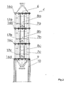
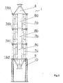
- Fig. 2 shows the experimental multifunction unit in a side view
- Fig. 3 shows the experimental multifunction unit in a sectional view
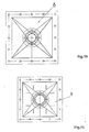
- Fig. 4 shows the experimental multifunction unit in a top view
- Fig. 5 shows the portions of the body of the experimental multifunction unit in a top view
- Fig. 6 shows one of the portions of the body of the experimental multifunction unit in a sectional view
- Fig. 7 shows the gaskets arranged between the individual portions of the unit
- Fig. 8 shows a built-in structure in a top view
- Fig. 9 shows a built-in structure in a side view
- Fig. 10 shows the upper transition part in a top view
- Fig. 11 shows the lower transition part in a bottom view.
- the technological flowchart which is shown in Fig. 1 , illustrates an experimental multifunction unit according to the invention wherein the unit comprises the reactor 1, the characteristics of the polluted flue gases, which flow through the unit, being monitored by the temperature measuring device 2, the pressure measuring device 2a, the flowrate measuring device 3, which establishes a corresponding pressure difference in the aperture 4, and the measuring device 5 for measuring the composition of flue gases.
- FIG. 10 The subsequent Figures 2 , 3 , 4 , 10 and 11 show the details of the reactor 1 in auxiliary views.
- the flue gases enter the body of the reactor 1 through the conduit 22, which is connected to the top inlet part 6 of the reactor.
- the details of the top inlet part 6 are illustrated in Fig. 10 .
- the reactor 1 has a square ground plan and the body of the reactor 1 is composed of three equal portions 7a, 7b and 7c.
- the individual portions 7a, 7b and 7c of the body of the reactor 1 and the transition parts, namely the top inlet part 6 and the bottom outlet part 9, are separated by the gaskets 16a to 16d, respectively, the latter being heat resistant up to the maximum temperature of 800 °C.
- each of the portions 7a, 7b and 7c of the body of the reactor 1 is provided with a general-purpose inlet 17a, 17b and 17c, e.g. with an inlet for supplying cooling air, for cooling the flue gases in case of a reactor provided with a split catalytic bed or for connecting auxiliary measuring instrumentation to the reactor.
- each of the portions 7 of the body of the reactor 1 is provided with a set of bayonet twist-lock mandrels 18 fixed to the inner side of the former and designed for securing an inner insulation layer and with the ribbing 19 designed to maintain the shape stability of the structure when the latter is subject to the operating temperature, as best seen in Fig. 6 .
- the unit also comprises the built-in structures 8a to 8c arranged inside of each portion 7 of the body of the reactor 1. The latter ones are visible in Figs. 8 and 9 .
- the individual portions 7 and the built-in structures 8 are interconnected with bolts in a detachable manner.
- the catalyst is filled in the hollow space 23 of the built-in structures 8a to 8c.
- Each layer of the bulk catalyst is provided with a covering layer of an inert material consisting of annular or spherical particles and ensuring the protection of the catalytic converter as well as the homogenization of the gas stream.
- a monolithic catalyst is used, such catalyst is secured inside the hollow space of the built-in structure 8 by means of the bolts 20 located on the side wall of the built-in structure 8.
- a screen 21 which is only indicated by the respective reference numeral in the figures, is placed onto the bolts 20 in order to prevent the catalyst from falling down through the given built-in structure 8.
- the purified flue gases leave the same by means of its bottom outlet part 9. The details of the bottom outlet part 9 are illustrated in Fig. 11 .
- the reactor 1 is supported by the pedestals 10. While the flue gases are passing through the reactor 1, the device 11 for measuring the pressure difference is determining the corresponding pressure loss of the flue gases across the catalyst.
- each rector block is provided with the temperature measuring devices 12a to 12d, respectively.
- the composition of the flue gases leaving the outlet of the reactor is measured by the measuring device 13.
- the uppermost portion 7a was filled with a monolithic matter, which was not covered by a catalytic layer and was serving for the homogenization of the gas stream, and the remaining two portions 7b and 7c were filled with a catalyst.
- the safety features of the unit according to the invention include the pressure vessel (14) for enabling the passageways of the flue gas to be inertized with nitrogen and the safety bypass valves (15a and 15b) for conducting the flue gas or waste gas away from the reactor.
- the entire pipework, which includes gas and fume passageways, as well as the reactor are provided with insulation.
- the individual monoliths are inserted into the interior space of the built-in structures 8a to 8c.
- the presented unit is a multifunction semi-operation one for eliminating pollutants from waste gas.
- the unit is variable, mobile and particularly suitable for performing long-term tests of catalysts both in laboratory and in semi-operation environments.
- the unit according to the invention enables the suitability of planned purification technologies to be verified before taking a final decision relating to the introduction of a new technology or to the modification of an existing technology. Thus, it minimizes the risk of possible economic losses which could arise due do the problems connected with the use of a technology that has not undergone any test in a semi-operation environment. With respect to the technological reliability and to the possibility of technical troubleshooting, it is very favourable to use a semi-operation device which is able to reveal possible technical problems and recommend a procedure for eliminating them.
- the unit according to the invention represents such a semi-operation device which is unique in the art.
- Conventional units, which are used for testing catalysts have notably smaller dimensions and the efficiency of a catalyst can be tested with only a very small amount of produced catalyst grains. This, however, does not reflect other problems, which may arise when the catalyst is used in an industrial scale, such as clogging, possible loss of activity and efficiency or adverse effect of catalytic poison which may be contained in the processed waste gas or flue gas.
- the proposed unit has compact constructional dimensions. Further advantages of the unit according to the invention consist in its versatility and mobility. The unit can be easily transported to the place where testing is to be performed. Owing to the multi-storey constructional arrangement with removable built-in structures, the unit according to the invention enables various techniques to be tested which are used for eliminating pollutants from waste gases or flue gases. In particular, the elimination of VOC, CO or deNO x with the use of both bulk and monolithic catalysts can be tested. After removing the built-in structures from the unit, even the elimination of deSO x and the filtration of solid matters can be tested.
- the unit according to the invention is primarily intended to be used with monolithic catalysts. Nevertheless, it can be also used with bulk catalysts carried by a fixed catalytic bed.
- the inlet and outlet gas passageways as well as the reactor itself are equipped with measuring devices which are adapted for determining the inlet and outlet compositions, flowrate, pressure, pressure loss and temperature of the respective gas.
- the protection of the catalyst is an important issue when processes comprising oxidising reactions are involved. This is due to a significant temperature increase during experimental oxidising processes. In the course of testing, the temperature might exceed the maximum value permitted for the catalyst, causing the latter to be damaged or even destroyed.
- the catalytic bed can be split into any number of portions. According to the particular application, cooling air may be introduced between such portions in order to prevent any possible damage to the catalyst used.
- the quarter-operation and semi-operation units i.e. those designed in the scale of 1:100 to 1:1000 when compared to full-size industrial applications
- the quarter-operation and semi-operation units are not widespread in the chemical industry and among the manufacturers who could use them for performing both short-term and long-term tests.
- the unit according to the invention enables the suitability of the application of the catalytic oxidation technology to be assessed in a semi-operation scale before taking a final decision relating to a possible technological investment.
Landscapes
- Engineering & Computer Science (AREA)
- Environmental & Geological Engineering (AREA)
- Chemical & Material Sciences (AREA)
- Health & Medical Sciences (AREA)
- Biomedical Technology (AREA)
- Analytical Chemistry (AREA)
- General Chemical & Material Sciences (AREA)
- Oil, Petroleum & Natural Gas (AREA)
- Chemical Kinetics & Catalysis (AREA)
- Exhaust Gas Treatment By Means Of Catalyst (AREA)
Priority Applications (1)
| Application Number | Priority Date | Filing Date | Title |
|---|---|---|---|
| EP13466019.0A EP2845640B1 (fr) | 2013-09-06 | 2013-09-06 | Unité de procédé multi-fonction pour la réduction de la concentration en polluants dans un effluent gazeux |
Applications Claiming Priority (1)
| Application Number | Priority Date | Filing Date | Title |
|---|---|---|---|
| EP13466019.0A EP2845640B1 (fr) | 2013-09-06 | 2013-09-06 | Unité de procédé multi-fonction pour la réduction de la concentration en polluants dans un effluent gazeux |
Publications (2)
| Publication Number | Publication Date |
|---|---|
| EP2845640A1 true EP2845640A1 (fr) | 2015-03-11 |
| EP2845640B1 EP2845640B1 (fr) | 2018-10-24 |
Family
ID=49484252
Family Applications (1)
| Application Number | Title | Priority Date | Filing Date |
|---|---|---|---|
| EP13466019.0A Not-in-force EP2845640B1 (fr) | 2013-09-06 | 2013-09-06 | Unité de procédé multi-fonction pour la réduction de la concentration en polluants dans un effluent gazeux |
Country Status (1)
| Country | Link |
|---|---|
| EP (1) | EP2845640B1 (fr) |
Citations (15)
| Publication number | Priority date | Publication date | Assignee | Title |
|---|---|---|---|---|
| US4004887A (en) | 1973-03-16 | 1977-01-25 | Tenneco Inc. | Catalytic converter having a resilient thermal-variation compensating monolith-mounting arrangement |
| US4186172A (en) | 1977-05-06 | 1980-01-29 | Audi Nsu Auto Union Aktiengesellschaft | Monolithic catalytic muffler having nondeposit welds |
| US4220625A (en) | 1976-10-20 | 1980-09-02 | Matsushita Electric Industrial Co., Ltd. | Exhaust gas control equipment |
| US4381590A (en) | 1979-06-19 | 1983-05-03 | Suddeutsche Kuhlerfabrik Julius Fr. Behr Gmbh & Co. Kg | Method for manufacturing a catalytic reactor carrier matrix |
| US4795616A (en) | 1987-06-19 | 1989-01-03 | General Motors Corporation | Catalytic converter monolithic substrate retention |
| EP0326388A2 (fr) * | 1988-01-29 | 1989-08-02 | Johnson Matthey, Inc., | Récupération de chaleur avec dispositif combiné pour éliminer les CO et NOX et méthode |
| US5055275A (en) | 1986-04-29 | 1991-10-08 | Kemira Oy | Reinforced catalytic unit intended for purifying exhaust gases |
| JPH1181728A (ja) * | 1997-09-05 | 1999-03-26 | Babcock Hitachi Kk | 反応塔とその建設工法 |
| JP2002219336A (ja) * | 2001-01-26 | 2002-08-06 | Babcock Hitachi Kk | 垂直流ダウンフロー型触媒反応器 |
| CA2478997A1 (fr) | 2002-03-08 | 2003-09-25 | Protemix Corporation Limited | Utilisation de tetraamines chelatant le cuivre destines au traitement de maladies cardiovasculaires et d'insuffisance cardiaque |
| FR2855767A1 (fr) * | 2003-06-06 | 2004-12-10 | Area Impianti Spa | Carter a cellules independantes apte a contenir des catalyseurs utilises en particulier pour le traitement des oxydes d'azote, de carbone, de metaux lourds et voc, des dioxines et des furannes |
| AU2005228862A1 (en) | 2004-03-23 | 2005-10-13 | W.R. Grace & Co.-Conn. | Storage of catalyst and/or additives and introduction of same into a fluidized catalytic cracking unit |
| WO2006079026A1 (fr) | 2005-01-21 | 2006-07-27 | Exxonmobil Research And Enginnering Company | Unite de reformage catalytique amelioree et fonctionnement de l'unite |
| US20060204417A1 (en) * | 2002-11-26 | 2006-09-14 | Rini Michael J | Method for treating emissions |
| US20110288184A1 (en) * | 2007-08-20 | 2011-11-24 | Consiglio Nazionale Delle Ricerche | Modular plant for removal of pollutants from flue gases produced bv industrial processes |
-
2013
- 2013-09-06 EP EP13466019.0A patent/EP2845640B1/fr not_active Not-in-force
Patent Citations (16)
| Publication number | Priority date | Publication date | Assignee | Title |
|---|---|---|---|---|
| US4004887A (en) | 1973-03-16 | 1977-01-25 | Tenneco Inc. | Catalytic converter having a resilient thermal-variation compensating monolith-mounting arrangement |
| US4220625A (en) | 1976-10-20 | 1980-09-02 | Matsushita Electric Industrial Co., Ltd. | Exhaust gas control equipment |
| US4186172A (en) | 1977-05-06 | 1980-01-29 | Audi Nsu Auto Union Aktiengesellschaft | Monolithic catalytic muffler having nondeposit welds |
| US4381590A (en) | 1979-06-19 | 1983-05-03 | Suddeutsche Kuhlerfabrik Julius Fr. Behr Gmbh & Co. Kg | Method for manufacturing a catalytic reactor carrier matrix |
| US5055275A (en) | 1986-04-29 | 1991-10-08 | Kemira Oy | Reinforced catalytic unit intended for purifying exhaust gases |
| US4795616A (en) | 1987-06-19 | 1989-01-03 | General Motors Corporation | Catalytic converter monolithic substrate retention |
| EP0326388A2 (fr) * | 1988-01-29 | 1989-08-02 | Johnson Matthey, Inc., | Récupération de chaleur avec dispositif combiné pour éliminer les CO et NOX et méthode |
| JPH1181728A (ja) * | 1997-09-05 | 1999-03-26 | Babcock Hitachi Kk | 反応塔とその建設工法 |
| JP2002219336A (ja) * | 2001-01-26 | 2002-08-06 | Babcock Hitachi Kk | 垂直流ダウンフロー型触媒反応器 |
| CA2478997A1 (fr) | 2002-03-08 | 2003-09-25 | Protemix Corporation Limited | Utilisation de tetraamines chelatant le cuivre destines au traitement de maladies cardiovasculaires et d'insuffisance cardiaque |
| US20060204417A1 (en) * | 2002-11-26 | 2006-09-14 | Rini Michael J | Method for treating emissions |
| FR2855767A1 (fr) * | 2003-06-06 | 2004-12-10 | Area Impianti Spa | Carter a cellules independantes apte a contenir des catalyseurs utilises en particulier pour le traitement des oxydes d'azote, de carbone, de metaux lourds et voc, des dioxines et des furannes |
| AU2005228862A1 (en) | 2004-03-23 | 2005-10-13 | W.R. Grace & Co.-Conn. | Storage of catalyst and/or additives and introduction of same into a fluidized catalytic cracking unit |
| WO2006079026A1 (fr) | 2005-01-21 | 2006-07-27 | Exxonmobil Research And Enginnering Company | Unite de reformage catalytique amelioree et fonctionnement de l'unite |
| AU2006206278A1 (en) | 2005-01-21 | 2006-07-27 | Exxonmobil Research And Engineering Company | Improved catalytic reformer unit and unit operation |
| US20110288184A1 (en) * | 2007-08-20 | 2011-11-24 | Consiglio Nazionale Delle Ricerche | Modular plant for removal of pollutants from flue gases produced bv industrial processes |
Non-Patent Citations (4)
| Title |
|---|
| CORDI E. M.; FALCONER J. L.: "Oxidation of volatile organic compounds on A1203, Pd/A1203 and PdO/A1203 catalysts", JOURNAL OF CATALYSTS, vol. 162, 1996, pages 104 - 117 |
| EVERAERT K.; BAEYENS J.: "Catalytic combustion of volatile organic compounds", JOURNAL OF HAZARDOUS MATERIALS B109, 2004, pages 113 - 139 |
| HECK R. M.; FARRAUTO R. J.; GULATI S. T.: "Catalytic air pollution control - Commercial Technology", 2002, JOHN WILEY & SONS |
| LIOTTA L. F.: "Catalytic oxidation of volatile organic compounds on supported noble metals", APPLIED CATALYSIS B: ENVIRONMENTAL, vol. 100, 2010, pages 403 - 412, XP027409617 |
Also Published As
| Publication number | Publication date |
|---|---|
| EP2845640B1 (fr) | 2018-10-24 |
Similar Documents
| Publication | Publication Date | Title |
|---|---|---|
| KR101634390B1 (ko) | 질소 산화물의 형성을 줄이거나 방지하는 암모니아와 일산화탄소의 이중 산화용 촉매 | |
| EP1874441B1 (fr) | Catalyseur d'oxydation d'ammoniac pour dispositifs fonctionnant au charbon | |
| US20110165040A1 (en) | Device for remediating emissions and method of manufacture | |
| US10994267B2 (en) | Vanadium trapping SCR system | |
| US4877592A (en) | Method of catalytic cleaning of exhaust gases | |
| GB2561083A (en) | Catalyst article for use in an emission treatment system | |
| Koebel et al. | Selective catalytic reduction of NO over commercial DeNO x catalysts: comparison of the measured and calculated performance | |
| Bahamonde et al. | An Experimental and Theoretical Investigation of the Behavior of a Monolithic Ti− V− W− Sepiolite Catalyst in the Reduction of NO x with NH3 | |
| CN101772378A (zh) | 去除废气或工艺气体中的有害烃的催化剂 | |
| US10705067B2 (en) | Methods and systems for testing performance of a catalyst element | |
| EP2845640B1 (fr) | Unité de procédé multi-fonction pour la réduction de la concentration en polluants dans un effluent gazeux | |
| KR20240034063A (ko) | 촉매 시스템 및 이를 사용하는 유체 크래킹 유닛의 오프-가스로부터 hcn을 제거하는 방법 및 상기 촉매 시스템을 포함하는 fcc 유닛 어셈블리 | |
| Goetz et al. | Catalyst Evaluation for the simultaneous reduction of sulfur dioxide and nitric oxide by carbon monoxide | |
| CN103047662A (zh) | 一种有机废气催化燃烧处理装置和处理方法 | |
| CN201815242U (zh) | 有机废气催化氧化净化处理系统装置 | |
| CN104826410A (zh) | 烟气过滤元件及制作方法 | |
| Gan et al. | Development of highly active coated monolith SCR catalyst with strong abrasion resistance for low-temperature application | |
| US11555621B1 (en) | Adapter for modular catalytic monoliths | |
| JP4328845B2 (ja) | ガス流の処理方法並びにガス浄化装置 | |
| CN212492405U (zh) | 一种自热维持式港口码头VOCs污染物的催化净化设备 | |
| Parus et al. | Catalytic oxidation of organic pollutants | |
| CN210376265U (zh) | 一种多功能催化剂活性评价中试装置 | |
| CZ26827U1 (cs) | Multifunkční poloprovozníjednotka pro snižování polutantů z odpadního plynu | |
| CZ307108B6 (cs) | Multifunkční poloprovozní jednotka pro snižování polutantů z odpadního plynu | |
| CN209985213U (zh) | 一种管道式光解催化氧化净化器 |
Legal Events
| Date | Code | Title | Description |
|---|---|---|---|
| 17P | Request for examination filed |
Effective date: 20130906 |
|
| AK | Designated contracting states |
Kind code of ref document: A1 Designated state(s): AL AT BE BG CH CY CZ DE DK EE ES FI FR GB GR HR HU IE IS IT LI LT LU LV MC MK MT NL NO PL PT RO RS SE SI SK SM TR |
|
| AX | Request for extension of the european patent |
Extension state: BA ME |
|
| PUAI | Public reference made under article 153(3) epc to a published international application that has entered the european phase |
Free format text: ORIGINAL CODE: 0009012 |
|
| R17P | Request for examination filed (corrected) |
Effective date: 20150723 |
|
| STAA | Information on the status of an ep patent application or granted ep patent |
Free format text: STATUS: EXAMINATION IS IN PROGRESS |
|
| 17Q | First examination report despatched |
Effective date: 20170202 |
|
| GRAP | Despatch of communication of intention to grant a patent |
Free format text: ORIGINAL CODE: EPIDOSNIGR1 |
|
| STAA | Information on the status of an ep patent application or granted ep patent |
Free format text: STATUS: GRANT OF PATENT IS INTENDED |
|
| INTG | Intention to grant announced |
Effective date: 20180112 |
|
| GRAS | Grant fee paid |
Free format text: ORIGINAL CODE: EPIDOSNIGR3 |
|
| GRAA | (expected) grant |
Free format text: ORIGINAL CODE: 0009210 |
|
| STAA | Information on the status of an ep patent application or granted ep patent |
Free format text: STATUS: THE PATENT HAS BEEN GRANTED |
|
| AK | Designated contracting states |
Kind code of ref document: B1 Designated state(s): AL AT BE BG CH CY CZ DE DK EE ES FI FR GB GR HR HU IE IS IT LI LT LU LV MC MK MT NL NO PL PT RO RS SE SI SK SM TR |
|
| REG | Reference to a national code |
Ref country code: CH Ref legal event code: EP |
|
| REG | Reference to a national code |
Ref country code: IE Ref legal event code: FG4D |
|
| REG | Reference to a national code |
Ref country code: AT Ref legal event code: REF Ref document number: 1056029 Country of ref document: AT Kind code of ref document: T Effective date: 20181115 |
|
| REG | Reference to a national code |
Ref country code: DE Ref legal event code: R096 Ref document number: 602013045490 Country of ref document: DE |
|
| REG | Reference to a national code |
Ref country code: NL Ref legal event code: MP Effective date: 20181024 |
|
| REG | Reference to a national code |
Ref country code: LT Ref legal event code: MG4D |
|
| REG | Reference to a national code |
Ref country code: AT Ref legal event code: MK05 Ref document number: 1056029 Country of ref document: AT Kind code of ref document: T Effective date: 20181024 |
|
| PG25 | Lapsed in a contracting state [announced via postgrant information from national office to epo] |
Ref country code: NL Free format text: LAPSE BECAUSE OF FAILURE TO SUBMIT A TRANSLATION OF THE DESCRIPTION OR TO PAY THE FEE WITHIN THE PRESCRIBED TIME-LIMIT Effective date: 20181024 |
|
| PG25 | Lapsed in a contracting state [announced via postgrant information from national office to epo] |
Ref country code: AT Free format text: LAPSE BECAUSE OF FAILURE TO SUBMIT A TRANSLATION OF THE DESCRIPTION OR TO PAY THE FEE WITHIN THE PRESCRIBED TIME-LIMIT Effective date: 20181024 Ref country code: HR Free format text: LAPSE BECAUSE OF FAILURE TO SUBMIT A TRANSLATION OF THE DESCRIPTION OR TO PAY THE FEE WITHIN THE PRESCRIBED TIME-LIMIT Effective date: 20181024 Ref country code: PL Free format text: LAPSE BECAUSE OF FAILURE TO SUBMIT A TRANSLATION OF THE DESCRIPTION OR TO PAY THE FEE WITHIN THE PRESCRIBED TIME-LIMIT Effective date: 20181024 Ref country code: NO Free format text: LAPSE BECAUSE OF FAILURE TO SUBMIT A TRANSLATION OF THE DESCRIPTION OR TO PAY THE FEE WITHIN THE PRESCRIBED TIME-LIMIT Effective date: 20190124 Ref country code: LV Free format text: LAPSE BECAUSE OF FAILURE TO SUBMIT A TRANSLATION OF THE DESCRIPTION OR TO PAY THE FEE WITHIN THE PRESCRIBED TIME-LIMIT Effective date: 20181024 Ref country code: FI Free format text: LAPSE BECAUSE OF FAILURE TO SUBMIT A TRANSLATION OF THE DESCRIPTION OR TO PAY THE FEE WITHIN THE PRESCRIBED TIME-LIMIT Effective date: 20181024 Ref country code: BG Free format text: LAPSE BECAUSE OF FAILURE TO SUBMIT A TRANSLATION OF THE DESCRIPTION OR TO PAY THE FEE WITHIN THE PRESCRIBED TIME-LIMIT Effective date: 20190124 Ref country code: IS Free format text: LAPSE BECAUSE OF FAILURE TO SUBMIT A TRANSLATION OF THE DESCRIPTION OR TO PAY THE FEE WITHIN THE PRESCRIBED TIME-LIMIT Effective date: 20190224 Ref country code: LT Free format text: LAPSE BECAUSE OF FAILURE TO SUBMIT A TRANSLATION OF THE DESCRIPTION OR TO PAY THE FEE WITHIN THE PRESCRIBED TIME-LIMIT Effective date: 20181024 Ref country code: ES Free format text: LAPSE BECAUSE OF FAILURE TO SUBMIT A TRANSLATION OF THE DESCRIPTION OR TO PAY THE FEE WITHIN THE PRESCRIBED TIME-LIMIT Effective date: 20181024 |
|
| PG25 | Lapsed in a contracting state [announced via postgrant information from national office to epo] |
Ref country code: GR Free format text: LAPSE BECAUSE OF FAILURE TO SUBMIT A TRANSLATION OF THE DESCRIPTION OR TO PAY THE FEE WITHIN THE PRESCRIBED TIME-LIMIT Effective date: 20190125 Ref country code: AL Free format text: LAPSE BECAUSE OF FAILURE TO SUBMIT A TRANSLATION OF THE DESCRIPTION OR TO PAY THE FEE WITHIN THE PRESCRIBED TIME-LIMIT Effective date: 20181024 Ref country code: PT Free format text: LAPSE BECAUSE OF FAILURE TO SUBMIT A TRANSLATION OF THE DESCRIPTION OR TO PAY THE FEE WITHIN THE PRESCRIBED TIME-LIMIT Effective date: 20190224 Ref country code: SE Free format text: LAPSE BECAUSE OF FAILURE TO SUBMIT A TRANSLATION OF THE DESCRIPTION OR TO PAY THE FEE WITHIN THE PRESCRIBED TIME-LIMIT Effective date: 20181024 Ref country code: RS Free format text: LAPSE BECAUSE OF FAILURE TO SUBMIT A TRANSLATION OF THE DESCRIPTION OR TO PAY THE FEE WITHIN THE PRESCRIBED TIME-LIMIT Effective date: 20181024 |
|
| REG | Reference to a national code |
Ref country code: DE Ref legal event code: R097 Ref document number: 602013045490 Country of ref document: DE |
|
| PG25 | Lapsed in a contracting state [announced via postgrant information from national office to epo] |
Ref country code: CZ Free format text: LAPSE BECAUSE OF FAILURE TO SUBMIT A TRANSLATION OF THE DESCRIPTION OR TO PAY THE FEE WITHIN THE PRESCRIBED TIME-LIMIT Effective date: 20181024 Ref country code: IT Free format text: LAPSE BECAUSE OF FAILURE TO SUBMIT A TRANSLATION OF THE DESCRIPTION OR TO PAY THE FEE WITHIN THE PRESCRIBED TIME-LIMIT Effective date: 20181024 Ref country code: DK Free format text: LAPSE BECAUSE OF FAILURE TO SUBMIT A TRANSLATION OF THE DESCRIPTION OR TO PAY THE FEE WITHIN THE PRESCRIBED TIME-LIMIT Effective date: 20181024 |
|
| PG25 | Lapsed in a contracting state [announced via postgrant information from national office to epo] |
Ref country code: RO Free format text: LAPSE BECAUSE OF FAILURE TO SUBMIT A TRANSLATION OF THE DESCRIPTION OR TO PAY THE FEE WITHIN THE PRESCRIBED TIME-LIMIT Effective date: 20181024 Ref country code: SK Free format text: LAPSE BECAUSE OF FAILURE TO SUBMIT A TRANSLATION OF THE DESCRIPTION OR TO PAY THE FEE WITHIN THE PRESCRIBED TIME-LIMIT Effective date: 20181024 Ref country code: SM Free format text: LAPSE BECAUSE OF FAILURE TO SUBMIT A TRANSLATION OF THE DESCRIPTION OR TO PAY THE FEE WITHIN THE PRESCRIBED TIME-LIMIT Effective date: 20181024 Ref country code: EE Free format text: LAPSE BECAUSE OF FAILURE TO SUBMIT A TRANSLATION OF THE DESCRIPTION OR TO PAY THE FEE WITHIN THE PRESCRIBED TIME-LIMIT Effective date: 20181024 |
|
| PLBE | No opposition filed within time limit |
Free format text: ORIGINAL CODE: 0009261 |
|
| STAA | Information on the status of an ep patent application or granted ep patent |
Free format text: STATUS: NO OPPOSITION FILED WITHIN TIME LIMIT |
|
| 26N | No opposition filed |
Effective date: 20190725 |
|
| PG25 | Lapsed in a contracting state [announced via postgrant information from national office to epo] |
Ref country code: SI Free format text: LAPSE BECAUSE OF FAILURE TO SUBMIT A TRANSLATION OF THE DESCRIPTION OR TO PAY THE FEE WITHIN THE PRESCRIBED TIME-LIMIT Effective date: 20181024 |
|
| PGFP | Annual fee paid to national office [announced via postgrant information from national office to epo] |
Ref country code: DE Payment date: 20190923 Year of fee payment: 7 |
|
| PG25 | Lapsed in a contracting state [announced via postgrant information from national office to epo] |
Ref country code: TR Free format text: LAPSE BECAUSE OF FAILURE TO SUBMIT A TRANSLATION OF THE DESCRIPTION OR TO PAY THE FEE WITHIN THE PRESCRIBED TIME-LIMIT Effective date: 20181024 |
|
| PG25 | Lapsed in a contracting state [announced via postgrant information from national office to epo] |
Ref country code: MC Free format text: LAPSE BECAUSE OF FAILURE TO SUBMIT A TRANSLATION OF THE DESCRIPTION OR TO PAY THE FEE WITHIN THE PRESCRIBED TIME-LIMIT Effective date: 20181024 |
|
| REG | Reference to a national code |
Ref country code: CH Ref legal event code: PL |
|
| PG25 | Lapsed in a contracting state [announced via postgrant information from national office to epo] |
Ref country code: LI Free format text: LAPSE BECAUSE OF NON-PAYMENT OF DUE FEES Effective date: 20190930 Ref country code: CH Free format text: LAPSE BECAUSE OF NON-PAYMENT OF DUE FEES Effective date: 20190930 Ref country code: IE Free format text: LAPSE BECAUSE OF NON-PAYMENT OF DUE FEES Effective date: 20190906 Ref country code: LU Free format text: LAPSE BECAUSE OF NON-PAYMENT OF DUE FEES Effective date: 20190906 |
|
| REG | Reference to a national code |
Ref country code: BE Ref legal event code: MM Effective date: 20190930 |
|
| PG25 | Lapsed in a contracting state [announced via postgrant information from national office to epo] |
Ref country code: BE Free format text: LAPSE BECAUSE OF NON-PAYMENT OF DUE FEES Effective date: 20190930 |
|
| GBPC | Gb: european patent ceased through non-payment of renewal fee |
Effective date: 20190906 |
|
| PG25 | Lapsed in a contracting state [announced via postgrant information from national office to epo] |
Ref country code: GB Free format text: LAPSE BECAUSE OF NON-PAYMENT OF DUE FEES Effective date: 20190906 |
|
| REG | Reference to a national code |
Ref country code: DE Ref legal event code: R119 Ref document number: 602013045490 Country of ref document: DE |
|
| PG25 | Lapsed in a contracting state [announced via postgrant information from national office to epo] |
Ref country code: CY Free format text: LAPSE BECAUSE OF FAILURE TO SUBMIT A TRANSLATION OF THE DESCRIPTION OR TO PAY THE FEE WITHIN THE PRESCRIBED TIME-LIMIT Effective date: 20181024 |
|
| PG25 | Lapsed in a contracting state [announced via postgrant information from national office to epo] |
Ref country code: MT Free format text: LAPSE BECAUSE OF FAILURE TO SUBMIT A TRANSLATION OF THE DESCRIPTION OR TO PAY THE FEE WITHIN THE PRESCRIBED TIME-LIMIT Effective date: 20181024 Ref country code: HU Free format text: LAPSE BECAUSE OF FAILURE TO SUBMIT A TRANSLATION OF THE DESCRIPTION OR TO PAY THE FEE WITHIN THE PRESCRIBED TIME-LIMIT; INVALID AB INITIO Effective date: 20130906 Ref country code: DE Free format text: LAPSE BECAUSE OF NON-PAYMENT OF DUE FEES Effective date: 20210401 Ref country code: FR Free format text: LAPSE BECAUSE OF NON-PAYMENT OF DUE FEES Effective date: 20190930 |
|
| PG25 | Lapsed in a contracting state [announced via postgrant information from national office to epo] |
Ref country code: MK Free format text: LAPSE BECAUSE OF FAILURE TO SUBMIT A TRANSLATION OF THE DESCRIPTION OR TO PAY THE FEE WITHIN THE PRESCRIBED TIME-LIMIT Effective date: 20181024 |