EP2845672A1 - Foret - Google Patents
Foret Download PDFInfo
- Publication number
- EP2845672A1 EP2845672A1 EP14183745.0A EP14183745A EP2845672A1 EP 2845672 A1 EP2845672 A1 EP 2845672A1 EP 14183745 A EP14183745 A EP 14183745A EP 2845672 A1 EP2845672 A1 EP 2845672A1
- Authority
- EP
- European Patent Office
- Prior art keywords
- drill
- core reinforcement
- width
- webs
- helix
- Prior art date
- Legal status (The legal status is an assumption and is not a legal conclusion. Google has not performed a legal analysis and makes no representation as to the accuracy of the status listed.)
- Granted
Links
Images


Classifications
-
- B—PERFORMING OPERATIONS; TRANSPORTING
- B23—MACHINE TOOLS; METAL-WORKING NOT OTHERWISE PROVIDED FOR
- B23B—TURNING; BORING
- B23B51/00—Tools for drilling machines
- B23B51/02—Twist drills
-
- B—PERFORMING OPERATIONS; TRANSPORTING
- B28—WORKING CEMENT, CLAY, OR STONE
- B28D—WORKING STONE OR STONE-LIKE MATERIALS
- B28D1/00—Working stone or stone-like materials, e.g. brick, concrete or glass, not provided for elsewhere; Machines, devices, tools therefor
- B28D1/14—Working stone or stone-like materials, e.g. brick, concrete or glass, not provided for elsewhere; Machines, devices, tools therefor by boring or drilling
- B28D1/146—Tools therefor
-
- B—PERFORMING OPERATIONS; TRANSPORTING
- B23—MACHINE TOOLS; METAL-WORKING NOT OTHERWISE PROVIDED FOR
- B23B—TURNING; BORING
- B23B2226/00—Materials of tools or workpieces not comprising a metal
- B23B2226/75—Stone, rock or concrete
-
- B—PERFORMING OPERATIONS; TRANSPORTING
- B23—MACHINE TOOLS; METAL-WORKING NOT OTHERWISE PROVIDED FOR
- B23B—TURNING; BORING
- B23B2251/00—Details of tools for drilling machines
- B23B2251/40—Flutes, i.e. chip conveying grooves
- B23B2251/406—Flutes, i.e. chip conveying grooves of special form not otherwise provided for
-
- B—PERFORMING OPERATIONS; TRANSPORTING
- B23—MACHINE TOOLS; METAL-WORKING NOT OTHERWISE PROVIDED FOR
- B23B—TURNING; BORING
- B23B2251/00—Details of tools for drilling machines
- B23B2251/44—Margins, i.e. the narrow portion of the land which is not cut away to provide clearance on the circumferential surface
- B23B2251/446—Drills with variable margins
Definitions
- the invention relates to a drill, according to the preamble of claim 1, in particular a rock drill with a equipped with a carbide insert drill head.
- Such a drill is for example from the DE 197 27 070 C2 known. This drill with core reinforcement has proven in practice to be particularly powerful and durable.
- Core reinforcement is understood as meaning a convexity in the direction of the longitudinal axis of the drill, that is to say a crowned structure of the drill core within each drill waste discharge groove, viewed in a longitudinal section of the drill.
- the invention has for its object to provide a drill according to the preamble of claim 1, whose long-term stability and resistance to breakage is further increased.
- a drill is provided with a core reinforcement whose back land width is lower at the drill head end than at the shank end of the lands or the drill spiral.
- the drill bit is provided in a conventional manner with a drill head with a carbide insert.
- the drill according to the invention is thus particularly suitable for rock and the like.
- the core reinforcement on the shank-side end of the helix leaner that is, less spherical.
- the rigidity and stability of the core is not affected by this or only to a very limited extent, because the absolute depth of the Bohrmehlabschreibnut at the top of the core reinforcement remains unchanged.
- the slimmer design provides more space for the removal of the dustbin by further increasing the volume of the dustbin discharge groove to the side of the center of the core reinforcement. This compensates by far the reduction of the volume or clearance available for the removal of the drilling dust per axial length section of the drill in the region of the shank-side end of the helix.
- the width of the back ribs is correspondingly lower than at the shank end.
- the drill is less rigid there.
- the more spherical configuration of the core reinforcement that is to say a design with larger radii of the convexity in the longitudinal section of the drill, there is a more massive spiral section available, which accordingly transmits the introduced impact energy better.
- the core reinforcement is made stiffer at the point where the drill is weakened by a weaker helix, and less rigid at the point where the drill is stiffer due to a stiffer helix having a wider back.
- Another advantage results from the reduction of the back width in the front area of the drill. Due to the narrower back webs, there is less contact surface between the drill hole and the drill. It results in less friction, which increases the drilling speed leads, especially during the creation of a borehole. The front part of the drill is already in contact with the drill hole at the beginning of the drilling, and its friction is decisive for the drilling performance.
- the shock wave introduced from the shaft end onto the drill can be better introduced into the drill spiral, whereby more impact energy is introduced into the drill head, which increases the drill performance.
- the change in shape of the core reinforcement is symmetrical, ie on both flanks of the core reinforcement mirror image of each other.
- the maximum possible increase in volume is achieved, which simultaneously prevents weakening of the core reinforcement.
- the core thickness of the drill measured at the tip or center of the core reinforcement, constant over the course of the helix. This avoids weakening the drill and reducing rigidity due to any reduction in core diameter.
- variable core reinforcement is combined with a drill spiral variable in the form of the variable spine width of the web.
- the shape of the core reinforcement changes over the course of the drill.
- the surface of the core reinforcement is reduced in a favorable embodiment of the shank end of the helix.
- the web over the course of the drill spiral considered a different mass. This surprisingly leads to avoid resonances due to the introduced longitudinal pulses of impact energy.
- this embodiment has the particular advantage that at the point at which the web wear is largest, the largest web mass is available. This point, ie the drill head end of the conveyor spiral, is most frequently in contact with the borehole surrounding the drill bit and is therefore exposed to the strongest wear. In this respect, in this embodiment, a particularly favorable wear compensation.
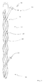
- the in Fig. 1 illustrated drill 10 has a drill bit 12 which extends from a shaft end 14, which is also referred to as the rear end, to a front end or drill bit end 16.
- the drill 10 has in the field of helix in a conventional manner a Bohrmehlabbownut 18, which is formed spirally encircling.
- a back web 20 is likewise designed to run in the same direction in a spiral manner, which back web 20 is embodied according to the invention in a special manner, as described below.
- the Bohrmehlabbow 18 has a core reinforcement 22.
- the core reinforcement 22 is more spherical in the area of the drill head end 16 and sharper or slimmer in the region of the shaft end 14 in the sense of a smaller cross section of the core reinforcement. Regarding the shape of the core reinforcement 22 in detail let the Figures 2 and 3 directed.
- the width 24 of the web 20 in the region of the drill head 16 is relatively narrow and the width 26 of the web 20 in the region of the shaft end 24 is large.
- the width 24 at the drill head end 16 is 2mm and the width 26 at the shaft end 14 is 5mm.
- the ratio of the back widths 24 to 26 can be adapted to the requirements in a wide range.
- the width ratio can also be 1 to 1.2 or up to 1 to 6.
- the dorsal ridge width ratio is between 1 to 1.5 and 1 to 3.5, more preferably between 1 in 2 and 1 in 3.
- the core reinforcement 22 changes in its configuration in the opposite direction to the change in the width 24 or 26.
- the core reinforcement 22 is wider in the area of the drill head end 16, so narrow at the point where the width 24 of the web 20 is narrower, and in the region of the shank end 14, at which point the width 26 of the web 20 is wider. This results in the desired compensation of the relatively narrower meal removal groove 18 in the region of the shank end 14 due to the higher width 24 and thus provides a relative increase in the Bohrmehlabssel 18, despite increasing the stiffness.
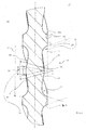
- Fig. 2 It can be seen that almost two courses of the helix are shown.
- the shaft end side web width 26a is larger than the drill head facing web width 26b.
- the Bohrmehlabbownut 18 has symmetrical outlet angles 30 and 32. This means the end angle of the Bohrmehlabbownut 18 to the web 20 toward meant, ie at the transition between the Bohrmehlabschreibnut 18 and the web 20th
- the outlet angle 30 at the drill-head-side end of the web 20 is exactly the same as the outlet angle 32 at the shank-side end of the web 20.
- this angle is 72 °, but can be adapted in many areas to the requirements. In order to limit the wear and to avoid jamming of the drill, the angle should, if possible, be significantly less than 85 °, preferably less than 80 °.
- the Bohrmehlabbow 18 is configured with the core reinforcement 22 in a special way.
- the core reinforcement 22 is quite slender.
- Their central radius 40 ie the radius of the convexity in the view according to Fig.2 in the immediate vicinity of the central center of the core reinforcement 22, is quite low. In the illustrated embodiment, it is significantly less than the nominal diameter of the drill, namely about half of the nominal diameter. This radius is detected via the central central 20 ° of the convex core reinforcement 22.
- the side radius 42 is significantly larger in contrast. In the illustrated embodiment, it is slightly less than the nominal diameter of the drill, which is slightly larger than the diameter of the drill in the region of the webs 20 due to the projecting in a conventional manner carbide tip. But it can also be slightly larger than the nominal diameter and can be preferably determined as an angle of about 35 ° over the central convexity of the core reinforcement 22.
- flanks of the core reinforcement 22 namely the leading edge 46 facing the drill head and the return flank 48, are straight and flat.
- the skew angle against the drill axis is between 5 and 18 degrees and in the illustrated embodiment about 10 degrees.
- the core reinforcement 22 becomes sharper and narrower.
- the Bohrmehlabschreibnut 18 in the region of the flutes 52 and 54 has an involute adhering structure, almost to the point where it merges into the center 60 of the core reinforcement 22.
- FIG. 3 shows the configuration of the Bohrmehlabschreibnut 18 and the core reinforcement 22 in the region of the drill head end of the coil.
- the core reinforcement 22 is in the view according to FIG Fig. 3 , so viewed in the longitudinal section through the drill, much more spherical. This results in that the central radius 40 and the side radius 42 coincide and are substantially larger than the respective radii according to FIG Fig. 2 , In the illustrated embodiment, both radii are about as large as twice the nominal diameter of the drill 10th
- the flutes 52 and 54 are such that, viewed from the outlet angles 30 and 32, they pass quite quickly into the convexity of the core reinforcement 22. Immediately following the concave region of the flutes 52 and 54, the convex region of the core reinforcement 22 adjoins in this embodiment.
- the convexity range of the core reinforcement 22 in this embodiment assumes a convexity width 70 that is opposite to the convexity width 70 in FIG Fig. 2 is significantly increased. It is significantly more than half the width 72 of the Bohrmehlabschreibnut 18.
- the width ratio is at the head end according to Fig. 3 about 0.8 to 1 while it is about 0.2 to 1 at the shank end.
- the ratio of the convexity width 70 to the drill dust removal groove width 72 is adaptable to the requirements in wide proportions, and a more convexity of the core reinforcement 22 is inherent with a relatively higher convexity width.
- width ratio of the widths 24 and 26 of the webs 20 here is 1 to 2
- the core reinforcement 22 changes in the opposite sense to the width change of the webs 20 as described above.
- the rear third 80 is equipped with a larger web width 26, and the two front thirds 82 of the drill 10 have a smaller web width 24. In between, there is a continuous transition.
Landscapes
- Engineering & Computer Science (AREA)
- Mechanical Engineering (AREA)
- Mining & Mineral Resources (AREA)
- Drilling Tools (AREA)
Applications Claiming Priority (1)
| Application Number | Priority Date | Filing Date | Title |
|---|---|---|---|
| DE102013109796.0A DE102013109796A1 (de) | 2013-09-06 | 2013-09-06 | Bohrer |
Publications (2)
| Publication Number | Publication Date |
|---|---|
| EP2845672A1 true EP2845672A1 (fr) | 2015-03-11 |
| EP2845672B1 EP2845672B1 (fr) | 2019-01-30 |
Family
ID=51492199
Family Applications (1)
| Application Number | Title | Priority Date | Filing Date |
|---|---|---|---|
| EP14183745.0A Active EP2845672B1 (fr) | 2013-09-06 | 2014-09-05 | Foret |
Country Status (2)
| Country | Link |
|---|---|
| EP (1) | EP2845672B1 (fr) |
| DE (1) | DE102013109796A1 (fr) |
Cited By (3)
| Publication number | Priority date | Publication date | Assignee | Title |
|---|---|---|---|---|
| WO2017080917A1 (fr) * | 2015-11-09 | 2017-05-18 | Robert Bosch Gmbh | Outil de forage |
| DE102016214386A1 (de) * | 2016-07-14 | 2018-01-18 | MAPAL Fabrik für Präzisionswerkzeuge Dr. Kress KG | Stufenbohrer |
| US11123809B2 (en) | 2018-06-14 | 2021-09-21 | Black & Decker Inc. | Drill bit |
Citations (3)
| Publication number | Priority date | Publication date | Assignee | Title |
|---|---|---|---|---|
| DE19727070C2 (de) | 1997-06-25 | 2000-07-06 | Drebo Werkzeugfab Gmbh | Bohrer |
| DE20108179U1 (de) * | 2001-05-15 | 2001-07-26 | Plica Werkzeugfabrik Ag, Mollis | Bohrer |
| DE10053342A1 (de) * | 2000-10-27 | 2002-05-08 | Hilti Ag | Wendelbohrer |
-
2013
- 2013-09-06 DE DE102013109796.0A patent/DE102013109796A1/de not_active Withdrawn
-
2014
- 2014-09-05 EP EP14183745.0A patent/EP2845672B1/fr active Active
Patent Citations (3)
| Publication number | Priority date | Publication date | Assignee | Title |
|---|---|---|---|---|
| DE19727070C2 (de) | 1997-06-25 | 2000-07-06 | Drebo Werkzeugfab Gmbh | Bohrer |
| DE10053342A1 (de) * | 2000-10-27 | 2002-05-08 | Hilti Ag | Wendelbohrer |
| DE20108179U1 (de) * | 2001-05-15 | 2001-07-26 | Plica Werkzeugfabrik Ag, Mollis | Bohrer |
Cited By (5)
| Publication number | Priority date | Publication date | Assignee | Title |
|---|---|---|---|---|
| WO2017080917A1 (fr) * | 2015-11-09 | 2017-05-18 | Robert Bosch Gmbh | Outil de forage |
| US10695951B2 (en) | 2015-11-09 | 2020-06-30 | Robert Bosch Gmbh | Drilling tool |
| DE102016214386A1 (de) * | 2016-07-14 | 2018-01-18 | MAPAL Fabrik für Präzisionswerkzeuge Dr. Kress KG | Stufenbohrer |
| US11077504B2 (en) | 2016-07-14 | 2021-08-03 | Mapal Fabrik Fur Prazisionswerkzeuge Dr. Kress Kg | Step drill |
| US11123809B2 (en) | 2018-06-14 | 2021-09-21 | Black & Decker Inc. | Drill bit |
Also Published As
| Publication number | Publication date |
|---|---|
| DE102013109796A1 (de) | 2015-03-12 |
| EP2845672B1 (fr) | 2019-01-30 |
Similar Documents
| Publication | Publication Date | Title |
|---|---|---|
| EP1273372B1 (fr) | Foret pour maçonnerie | |
| EP2237913B1 (fr) | Outil de perçage et pointe correspondante | |
| EP2934802B2 (fr) | Foret hélicoïdal | |
| DE3339211C2 (fr) | ||
| EP2454043B1 (fr) | Foret | |
| EP2117752B1 (fr) | Dispositif de forage de roche | |
| EP3150315B1 (fr) | Fraise à queue | |
| EP1047857B1 (fr) | Perforateur de roches | |
| WO2011038896A1 (fr) | Foret | |
| DE102007062539B4 (de) | Bohrwerkzeug | |
| DE102014207502A1 (de) | Rotationswerkzeug sowie Werkzeugkopf | |
| EP2845672B1 (fr) | Foret | |
| WO2003051565A1 (fr) | Outil de perçage par percussion ou par martelage | |
| DE102008033046B4 (de) | Bohrer mit einem Hartmetallelement an dem Bohrerkopf | |
| EP1558851B1 (fr) | Vis pour mat riaux durs | |
| EP1217165B1 (fr) | Foret à roche | |
| DE102012109913B4 (de) | Bohrer | |
| DE102008062298B4 (de) | Bohrkörper | |
| EP3943763B1 (fr) | Vis à bois ou à matière plastique | |
| DE102015116624B4 (de) | Schaftfräser | |
| EP3150347B1 (fr) | Foret | |
| DE19860528B4 (de) | Gesteinsbohrer für Hammerbohrmaschinen | |
| DE20016012U1 (de) | Gesteinsbohrer | |
| DE20205558U1 (de) | Bohrer | |
| EP0322554A1 (fr) | Trépan de roche |
Legal Events
| Date | Code | Title | Description |
|---|---|---|---|
| 17P | Request for examination filed |
Effective date: 20140905 |
|
| AK | Designated contracting states |
Kind code of ref document: A1 Designated state(s): AL AT BE BG CH CY CZ DE DK EE ES FI FR GB GR HR HU IE IS IT LI LT LU LV MC MK MT NL NO PL PT RO RS SE SI SK SM TR |
|
| AX | Request for extension of the european patent |
Extension state: BA ME |
|
| PUAI | Public reference made under article 153(3) epc to a published international application that has entered the european phase |
Free format text: ORIGINAL CODE: 0009012 |
|
| R17P | Request for examination filed (corrected) |
Effective date: 20150317 |
|
| RBV | Designated contracting states (corrected) |
Designated state(s): AL AT BE BG CH CY CZ DE DK EE ES FI FR GB GR HR HU IE IS IT LI LT LU LV MC MK MT NL NO PL PT RO RS SE SI SK SM TR |
|
| RIC1 | Information provided on ipc code assigned before grant |
Ipc: B23B 51/02 20060101AFI20180626BHEP Ipc: B28D 1/14 20060101ALI20180626BHEP |
|
| GRAP | Despatch of communication of intention to grant a patent |
Free format text: ORIGINAL CODE: EPIDOSNIGR1 |
|
| STAA | Information on the status of an ep patent application or granted ep patent |
Free format text: STATUS: GRANT OF PATENT IS INTENDED |
|
| INTG | Intention to grant announced |
Effective date: 20180813 |
|
| GRAS | Grant fee paid |
Free format text: ORIGINAL CODE: EPIDOSNIGR3 |
|
| GRAA | (expected) grant |
Free format text: ORIGINAL CODE: 0009210 |
|
| STAA | Information on the status of an ep patent application or granted ep patent |
Free format text: STATUS: THE PATENT HAS BEEN GRANTED |
|
| AK | Designated contracting states |
Kind code of ref document: B1 Designated state(s): AL AT BE BG CH CY CZ DE DK EE ES FI FR GB GR HR HU IE IS IT LI LT LU LV MC MK MT NL NO PL PT RO RS SE SI SK SM TR |
|
| REG | Reference to a national code |
Ref country code: GB Ref legal event code: FG4D Free format text: NOT ENGLISH |
|
| REG | Reference to a national code |
Ref country code: CH Ref legal event code: EP |
|
| REG | Reference to a national code |
Ref country code: AT Ref legal event code: REF Ref document number: 1092842 Country of ref document: AT Kind code of ref document: T Effective date: 20190215 |
|
| REG | Reference to a national code |
Ref country code: IE Ref legal event code: FG4D Free format text: LANGUAGE OF EP DOCUMENT: GERMAN |
|
| REG | Reference to a national code |
Ref country code: DE Ref legal event code: R096 Ref document number: 502014010694 Country of ref document: DE |
|
| REG | Reference to a national code |
Ref country code: LT Ref legal event code: MG4D |
|
| REG | Reference to a national code |
Ref country code: NL Ref legal event code: MP Effective date: 20190130 |
|
| PG25 | Lapsed in a contracting state [announced via postgrant information from national office to epo] |
Ref country code: ES Free format text: LAPSE BECAUSE OF FAILURE TO SUBMIT A TRANSLATION OF THE DESCRIPTION OR TO PAY THE FEE WITHIN THE PRESCRIBED TIME-LIMIT Effective date: 20190130 Ref country code: SE Free format text: LAPSE BECAUSE OF FAILURE TO SUBMIT A TRANSLATION OF THE DESCRIPTION OR TO PAY THE FEE WITHIN THE PRESCRIBED TIME-LIMIT Effective date: 20190130 Ref country code: NO Free format text: LAPSE BECAUSE OF FAILURE TO SUBMIT A TRANSLATION OF THE DESCRIPTION OR TO PAY THE FEE WITHIN THE PRESCRIBED TIME-LIMIT Effective date: 20190430 Ref country code: PT Free format text: LAPSE BECAUSE OF FAILURE TO SUBMIT A TRANSLATION OF THE DESCRIPTION OR TO PAY THE FEE WITHIN THE PRESCRIBED TIME-LIMIT Effective date: 20190530 Ref country code: PL Free format text: LAPSE BECAUSE OF FAILURE TO SUBMIT A TRANSLATION OF THE DESCRIPTION OR TO PAY THE FEE WITHIN THE PRESCRIBED TIME-LIMIT Effective date: 20190130 Ref country code: LT Free format text: LAPSE BECAUSE OF FAILURE TO SUBMIT A TRANSLATION OF THE DESCRIPTION OR TO PAY THE FEE WITHIN THE PRESCRIBED TIME-LIMIT Effective date: 20190130 Ref country code: FI Free format text: LAPSE BECAUSE OF FAILURE TO SUBMIT A TRANSLATION OF THE DESCRIPTION OR TO PAY THE FEE WITHIN THE PRESCRIBED TIME-LIMIT Effective date: 20190130 Ref country code: NL Free format text: LAPSE BECAUSE OF FAILURE TO SUBMIT A TRANSLATION OF THE DESCRIPTION OR TO PAY THE FEE WITHIN THE PRESCRIBED TIME-LIMIT Effective date: 20190130 |
|
| PG25 | Lapsed in a contracting state [announced via postgrant information from national office to epo] |
Ref country code: BG Free format text: LAPSE BECAUSE OF FAILURE TO SUBMIT A TRANSLATION OF THE DESCRIPTION OR TO PAY THE FEE WITHIN THE PRESCRIBED TIME-LIMIT Effective date: 20190430 Ref country code: GR Free format text: LAPSE BECAUSE OF FAILURE TO SUBMIT A TRANSLATION OF THE DESCRIPTION OR TO PAY THE FEE WITHIN THE PRESCRIBED TIME-LIMIT Effective date: 20190501 Ref country code: RS Free format text: LAPSE BECAUSE OF FAILURE TO SUBMIT A TRANSLATION OF THE DESCRIPTION OR TO PAY THE FEE WITHIN THE PRESCRIBED TIME-LIMIT Effective date: 20190130 Ref country code: HR Free format text: LAPSE BECAUSE OF FAILURE TO SUBMIT A TRANSLATION OF THE DESCRIPTION OR TO PAY THE FEE WITHIN THE PRESCRIBED TIME-LIMIT Effective date: 20190130 Ref country code: IS Free format text: LAPSE BECAUSE OF FAILURE TO SUBMIT A TRANSLATION OF THE DESCRIPTION OR TO PAY THE FEE WITHIN THE PRESCRIBED TIME-LIMIT Effective date: 20190530 Ref country code: LV Free format text: LAPSE BECAUSE OF FAILURE TO SUBMIT A TRANSLATION OF THE DESCRIPTION OR TO PAY THE FEE WITHIN THE PRESCRIBED TIME-LIMIT Effective date: 20190130 |
|
| PG25 | Lapsed in a contracting state [announced via postgrant information from national office to epo] |
Ref country code: SK Free format text: LAPSE BECAUSE OF FAILURE TO SUBMIT A TRANSLATION OF THE DESCRIPTION OR TO PAY THE FEE WITHIN THE PRESCRIBED TIME-LIMIT Effective date: 20190130 Ref country code: RO Free format text: LAPSE BECAUSE OF FAILURE TO SUBMIT A TRANSLATION OF THE DESCRIPTION OR TO PAY THE FEE WITHIN THE PRESCRIBED TIME-LIMIT Effective date: 20190130 Ref country code: EE Free format text: LAPSE BECAUSE OF FAILURE TO SUBMIT A TRANSLATION OF THE DESCRIPTION OR TO PAY THE FEE WITHIN THE PRESCRIBED TIME-LIMIT Effective date: 20190130 Ref country code: DK Free format text: LAPSE BECAUSE OF FAILURE TO SUBMIT A TRANSLATION OF THE DESCRIPTION OR TO PAY THE FEE WITHIN THE PRESCRIBED TIME-LIMIT Effective date: 20190130 Ref country code: AL Free format text: LAPSE BECAUSE OF FAILURE TO SUBMIT A TRANSLATION OF THE DESCRIPTION OR TO PAY THE FEE WITHIN THE PRESCRIBED TIME-LIMIT Effective date: 20190130 Ref country code: CZ Free format text: LAPSE BECAUSE OF FAILURE TO SUBMIT A TRANSLATION OF THE DESCRIPTION OR TO PAY THE FEE WITHIN THE PRESCRIBED TIME-LIMIT Effective date: 20190130 |
|
| REG | Reference to a national code |
Ref country code: DE Ref legal event code: R097 Ref document number: 502014010694 Country of ref document: DE |
|
| PG25 | Lapsed in a contracting state [announced via postgrant information from national office to epo] |
Ref country code: SM Free format text: LAPSE BECAUSE OF FAILURE TO SUBMIT A TRANSLATION OF THE DESCRIPTION OR TO PAY THE FEE WITHIN THE PRESCRIBED TIME-LIMIT Effective date: 20190130 |
|
| PLBE | No opposition filed within time limit |
Free format text: ORIGINAL CODE: 0009261 |
|
| STAA | Information on the status of an ep patent application or granted ep patent |
Free format text: STATUS: NO OPPOSITION FILED WITHIN TIME LIMIT |
|
| 26N | No opposition filed |
Effective date: 20191031 |
|
| PG25 | Lapsed in a contracting state [announced via postgrant information from national office to epo] |
Ref country code: SI Free format text: LAPSE BECAUSE OF FAILURE TO SUBMIT A TRANSLATION OF THE DESCRIPTION OR TO PAY THE FEE WITHIN THE PRESCRIBED TIME-LIMIT Effective date: 20190130 |
|
| PG25 | Lapsed in a contracting state [announced via postgrant information from national office to epo] |
Ref country code: TR Free format text: LAPSE BECAUSE OF FAILURE TO SUBMIT A TRANSLATION OF THE DESCRIPTION OR TO PAY THE FEE WITHIN THE PRESCRIBED TIME-LIMIT Effective date: 20190130 |
|
| REG | Reference to a national code |
Ref country code: DE Ref legal event code: R119 Ref document number: 502014010694 Country of ref document: DE Ref country code: DE Ref legal event code: R409 Ref document number: 502014010694 Country of ref document: DE |
|
| PG25 | Lapsed in a contracting state [announced via postgrant information from national office to epo] |
Ref country code: MC Free format text: LAPSE BECAUSE OF FAILURE TO SUBMIT A TRANSLATION OF THE DESCRIPTION OR TO PAY THE FEE WITHIN THE PRESCRIBED TIME-LIMIT Effective date: 20190130 |
|
| REG | Reference to a national code |
Ref country code: CH Ref legal event code: PL |
|
| PG25 | Lapsed in a contracting state [announced via postgrant information from national office to epo] |
Ref country code: CH Free format text: LAPSE BECAUSE OF NON-PAYMENT OF DUE FEES Effective date: 20190930 Ref country code: LI Free format text: LAPSE BECAUSE OF NON-PAYMENT OF DUE FEES Effective date: 20190930 Ref country code: LU Free format text: LAPSE BECAUSE OF NON-PAYMENT OF DUE FEES Effective date: 20190905 Ref country code: IE Free format text: LAPSE BECAUSE OF NON-PAYMENT OF DUE FEES Effective date: 20190905 |
|
| REG | Reference to a national code |
Ref country code: BE Ref legal event code: MM Effective date: 20190930 |
|
| PG25 | Lapsed in a contracting state [announced via postgrant information from national office to epo] |
Ref country code: BE Free format text: LAPSE BECAUSE OF NON-PAYMENT OF DUE FEES Effective date: 20190930 |
|
| REG | Reference to a national code |
Ref country code: AT Ref legal event code: MM01 Ref document number: 1092842 Country of ref document: AT Kind code of ref document: T Effective date: 20190905 |
|
| PG25 | Lapsed in a contracting state [announced via postgrant information from national office to epo] |
Ref country code: AT Free format text: LAPSE BECAUSE OF NON-PAYMENT OF DUE FEES Effective date: 20190905 |
|
| PG25 | Lapsed in a contracting state [announced via postgrant information from national office to epo] |
Ref country code: CY Free format text: LAPSE BECAUSE OF FAILURE TO SUBMIT A TRANSLATION OF THE DESCRIPTION OR TO PAY THE FEE WITHIN THE PRESCRIBED TIME-LIMIT Effective date: 20190130 |
|
| PG25 | Lapsed in a contracting state [announced via postgrant information from national office to epo] |
Ref country code: HU Free format text: LAPSE BECAUSE OF FAILURE TO SUBMIT A TRANSLATION OF THE DESCRIPTION OR TO PAY THE FEE WITHIN THE PRESCRIBED TIME-LIMIT; INVALID AB INITIO Effective date: 20140905 Ref country code: MT Free format text: LAPSE BECAUSE OF FAILURE TO SUBMIT A TRANSLATION OF THE DESCRIPTION OR TO PAY THE FEE WITHIN THE PRESCRIBED TIME-LIMIT Effective date: 20190130 |
|
| PG25 | Lapsed in a contracting state [announced via postgrant information from national office to epo] |
Ref country code: MK Free format text: LAPSE BECAUSE OF FAILURE TO SUBMIT A TRANSLATION OF THE DESCRIPTION OR TO PAY THE FEE WITHIN THE PRESCRIBED TIME-LIMIT Effective date: 20190130 |
|
| P01 | Opt-out of the competence of the unified patent court (upc) registered |
Effective date: 20230530 |
|
| PGFP | Annual fee paid to national office [announced via postgrant information from national office to epo] |
Ref country code: DE Payment date: 20250819 Year of fee payment: 12 |
|
| PGFP | Annual fee paid to national office [announced via postgrant information from national office to epo] |
Ref country code: IT Payment date: 20250922 Year of fee payment: 12 |
|
| PGFP | Annual fee paid to national office [announced via postgrant information from national office to epo] |
Ref country code: GB Payment date: 20250917 Year of fee payment: 12 |
|
| PGFP | Annual fee paid to national office [announced via postgrant information from national office to epo] |
Ref country code: FR Payment date: 20250925 Year of fee payment: 12 |