EP2845701A1 - Dispositif et procédé de découpe et de manipulation d'une section extensive, notamment pour la fabrication de composants en matériau en fibres composites - Google Patents
Dispositif et procédé de découpe et de manipulation d'une section extensive, notamment pour la fabrication de composants en matériau en fibres composites Download PDFInfo
- Publication number
- EP2845701A1 EP2845701A1 EP14184084.3A EP14184084A EP2845701A1 EP 2845701 A1 EP2845701 A1 EP 2845701A1 EP 14184084 A EP14184084 A EP 14184084A EP 2845701 A1 EP2845701 A1 EP 2845701A1
- Authority
- EP
- European Patent Office
- Prior art keywords
- punching
- fiber fabric
- contour
- cutting
- handling
- Prior art date
- Legal status (The legal status is an assumption and is not a legal conclusion. Google has not performed a legal analysis and makes no representation as to the accuracy of the status listed.)
- Withdrawn
Links
- 239000000835 fiber Substances 0.000 title claims abstract description 124
- 238000005520 cutting process Methods 0.000 title claims abstract description 73
- 238000004519 manufacturing process Methods 0.000 title claims abstract description 18
- 238000000034 method Methods 0.000 title claims abstract description 18
- 239000002131 composite material Substances 0.000 title claims abstract description 16
- 238000004080 punching Methods 0.000 claims abstract description 134
- 239000004744 fabric Substances 0.000 claims abstract description 81
- 239000002699 waste material Substances 0.000 claims description 3
- 230000008878 coupling Effects 0.000 claims description 2
- 238000010168 coupling process Methods 0.000 claims description 2
- 238000005859 coupling reaction Methods 0.000 claims description 2
- 239000010410 layer Substances 0.000 description 13
- 239000000463 material Substances 0.000 description 5
- 239000004918 carbon fiber reinforced polymer Substances 0.000 description 4
- 239000011265 semifinished product Substances 0.000 description 2
- 238000003860 storage Methods 0.000 description 2
- 230000003213 activating effect Effects 0.000 description 1
- 239000000853 adhesive Substances 0.000 description 1
- 230000001070 adhesive effect Effects 0.000 description 1
- 230000001419 dependent effect Effects 0.000 description 1
- 239000012636 effector Substances 0.000 description 1
- 239000003733 fiber-reinforced composite Substances 0.000 description 1
- 230000010354 integration Effects 0.000 description 1
- 238000009940 knitting Methods 0.000 description 1
- 238000000465 moulding Methods 0.000 description 1
- 239000011347 resin Substances 0.000 description 1
- 229920005989 resin Polymers 0.000 description 1
- 239000011342 resin composition Substances 0.000 description 1
- 238000005096 rolling process Methods 0.000 description 1
- 230000035945 sensitivity Effects 0.000 description 1
- 238000000926 separation method Methods 0.000 description 1
- 238000004904 shortening Methods 0.000 description 1
- 239000002356 single layer Substances 0.000 description 1
- 230000003319 supportive effect Effects 0.000 description 1
- 239000000725 suspension Substances 0.000 description 1
- 229920001169 thermoplastic Polymers 0.000 description 1
- 239000004416 thermosoftening plastic Substances 0.000 description 1
- 238000001721 transfer moulding Methods 0.000 description 1
- 238000003466 welding Methods 0.000 description 1
Images

Classifications
-
- B—PERFORMING OPERATIONS; TRANSPORTING
- B26—HAND CUTTING TOOLS; CUTTING; SEVERING
- B26F—PERFORATING; PUNCHING; CUTTING-OUT; STAMPING-OUT; SEVERING BY MEANS OTHER THAN CUTTING
- B26F1/00—Perforating; Punching; Cutting-out; Stamping-out; Apparatus therefor
- B26F1/38—Cutting-out; Stamping-out
- B26F1/40—Cutting-out; Stamping-out using a press, e.g. of the ram type
-
- B—PERFORMING OPERATIONS; TRANSPORTING
- B25—HAND TOOLS; PORTABLE POWER-DRIVEN TOOLS; MANIPULATORS
- B25J—MANIPULATORS; CHAMBERS PROVIDED WITH MANIPULATION DEVICES
- B25J11/00—Manipulators not otherwise provided for
- B25J11/005—Manipulators for mechanical processing tasks
- B25J11/0055—Cutting
-
- B—PERFORMING OPERATIONS; TRANSPORTING
- B25—HAND TOOLS; PORTABLE POWER-DRIVEN TOOLS; MANIPULATORS
- B25J—MANIPULATORS; CHAMBERS PROVIDED WITH MANIPULATION DEVICES
- B25J15/00—Gripping heads and other end effectors
- B25J15/0052—Gripping heads and other end effectors multiple gripper units or multiple end effectors
- B25J15/0066—Gripping heads and other end effectors multiple gripper units or multiple end effectors with different types of end effectors, e.g. gripper and welding gun
-
- B—PERFORMING OPERATIONS; TRANSPORTING
- B25—HAND TOOLS; PORTABLE POWER-DRIVEN TOOLS; MANIPULATORS
- B25J—MANIPULATORS; CHAMBERS PROVIDED WITH MANIPULATION DEVICES
- B25J15/00—Gripping heads and other end effectors
- B25J15/06—Gripping heads and other end effectors with vacuum or magnetic holding means
- B25J15/0616—Gripping heads and other end effectors with vacuum or magnetic holding means with vacuum
-
- B—PERFORMING OPERATIONS; TRANSPORTING
- B26—HAND CUTTING TOOLS; CUTTING; SEVERING
- B26D—CUTTING; DETAILS COMMON TO MACHINES FOR PERFORATING, PUNCHING, CUTTING-OUT, STAMPING-OUT OR SEVERING
- B26D7/00—Details of apparatus for cutting, cutting-out, stamping-out, punching, perforating, or severing by means other than cutting
- B26D7/18—Means for removing cut-out material or waste
- B26D7/1845—Means for removing cut-out material or waste by non mechanical means
- B26D7/1863—Means for removing cut-out material or waste by non mechanical means by suction
Definitions
- the invention relates to a device for cutting and handling a planar blank made of fiber fabric or fiber fabric, in particular for the production of components made of fiber composite material, with a cutting device and a handling device according to the preamble of claim 1 and a corresponding method according to claim 15.
- RTM Resin Transfer Molding
- fiber webs or fiber webs are unwound from a roll and cut into individual blank layers.
- the cutting is usually carried out with a conventional cutting device, ie on a cutting table by means of a rolling knife, ultrasonic knife or oscillating knife, a contour is cut off in sections and tailored so.
- a handling device such as a robot with appropriate gripping system, for example, with suction pads, picked up and transported to the drapery device. Since, in the described cutting process, a superimposed feed rate of the knives used there correspondingly exists, it is thus easy for the movement of the knives to lead to a distortion of the fiber orientation.
- German patent DE 10 2007 061 427 B4 describes a device for cutting and handling a substantially planar blank from a CFRP semi-finished product and a corresponding method, wherein the blank is there by means of a cutting device formed from a rotating oscillating blade or a corresponding cutting edge and then after lifting the cutting device so formed Blanks of the CFRP semi-finished product can be sucked by means of a vacuum effector.
- the handling of blanks compared to the handling can be improved by hand, but on the one hand, the corresponding system is quite complex and on the other hand, it can still cut and shifts the fibers when cutting and handling of the blanks the blanks come because the local cutting device acts only localized and so can move the fibers there, and because different parts of the system for the different operations of cutting and handling / suction are used.
- the object of the invention is achieved by a device for Cropping and handling a planar blank made of fiber fabric or fiber fabric, in particular for the production of components made of fiber composite material, having the features of claim 1 and a corresponding method having the features of claim 15.
- Preferred embodiments are defined in the respective dependent claims.
- the invention generally refers to a layer structure of different fiber layers or fiber fabrics under a fiber layer. For example, it is not uncommon to superimpose or lay several fiber webs (of different rolls on a punching table) (fiber scrims).
- the cutting device is a punching device with at least one punching knife, which forms a contour, a punching table on which the fiber fabric or fiber layer is stored, and a punch press, which presses the punching knife against the punching table and through the fiber fabric or fiber fabric while performing a punching stroke and in that the handling device has at least one holder which can be activated within the contour of the at least one punching knife and which is designed in such a way that the blank cut out of the fiber fabric or fiber structure corresponding to the contour is at least liftable by the punching table.
- the handling device which thereby essentially as described may correspond to the punching device, received by the punching table.
- the integrated activatable holder which is preferably integrated in the inner region of the contour of the punching blade (ie within the rotating punching blade) and may preferably be formed by a vacuum suction device.
- the punching waste remains lying on the punching table and is held back by it adapted to the outer contour of the punch blade hold down when lifting there, especially during the initial time of lifting.
- the design according to the invention with the activatable holder integrated within the contour of the at least one punching blade, that is to say the integration of the handling device into the cutting device, also leads to a particularly compact and comparatively simple solution according to the invention. Furthermore, the cycle time in the production of molded parts can be shortened by the punching process according to the invention. This shortening of the cycle time also results according to the invention by the possibility of integrating punching and lifting / gripping with an integrated device and in one step or directly one after the other.
- the contour of the punching knife may be a circumferentially closed contour.
- the edge contour of a fiber fabric or of the fiber fabric can already correspond at least partially to the edge contour of the cutout, for example by providing a straight edge of the fiber fabric or the fiber fabric as the edge of the blank and correspondingly there is no punching knife provided or rather used as a boundary ,
- the holder according to the invention may be a vacuum suction device, wherein suction openings thereof are arranged within the contour of the punching knife.
- the cutting device with the handling device in the three xyz spatial axes can be moved.
- the holder or also the cutting device with the handling device can be fastened to an arm of a robot, so that it can be moved in three x-y-z spatial axes.
- the punching device with the integrated holder of the handling device can therefore preferably have one or more driving axes, ie. H. into the three x, y, z spatial axes, be movable.
- the blank thus held accordingly can be transported by the cutting device to a draping table.
- There the cut can be stored by activating ejectors.
- a rotation of the corresponding device takes place, for example about the z-axis, in order to obtain a desired fiber orientation of the planar blank with respect to the component to be produced.
- the flexibility of the device according to the invention can be further increased by the use of a robot.
- the device according to the invention can preferably be designed such that the punching device is picked up by the robot from a arranged magazine and positioned in the corresponding cutting position.
- raising and lowering hold-down devices can be provided around the contour, so that remaining stand waste and / or the fiber fabric or fiber fabric located there can be preserved on the punching table outside the contour of the punching knife.
- the hold-down devices can also be pivotable.
- the hold-down devices may expediently be arranged on the punching table and / or on the punching knife and be provided at least partially outside the contour and / or at least partially around the contour.
- punching blades of the same or different contour can be arranged.
- the contour which is defined by the maximum intended punching surface
- punching devices may be provided with punching blades, so that when punching several different blanks can be produced. It can be stamped inside a larger contour and further, (smaller) inner contours (in a common punching stroke and / or successively), z. B. cutouts, window openings, holes, centering or the like.
- an additional cutting device which can be moved over the punching table in at least two x-y spatial axes.
- an additional conventional cutting system with x, y-axis slidable suspension in addition to cutting smaller contours, z. B. of cross-cuts, combined with the device according to the invention can be used.
- the punching device may have a punching knife changing device with a coupling plate which has at least passages and / or connections for air ducts and / or energy supply lines.
- the punching knife may preferably be heatable, wherein it particularly preferably has electrical connections and is thus electrically resistively heated or at least electrically heatable by means of at least one Peltier element.
- the heatability of the knife is especially useful if additional thermoplastic knitting threads are present in the fiber fabric or fiber fabric, so that they can be melted accordingly during cutting.
- One advantage is that in this case a kind of welding of the edges can be carried out, which reduces the sensitivity of the cutting edges.
- the punching knife may preferably be electrically heated or cooled by means of at least one Peltier element.
- the inventive method is used for cutting and handling a planar blank of fiber fabric or fiber fabric for the production of components made of fiber composite material, using a cutting device and a handling device, according to the invention, the fiber fabric or fiber fabric is placed on a punching table, the cutting device is a punching device with at least a punching knife, which forms a contour, and a punching press, which presses the punching knife against the punching table and through the fiber fabric or fiber web while performing a punching stroke, and wherein the handling device has at least one integrated within the contour of the at least one punchable activatable holder, which so is designed so that the cut out of the fiber fabric or fiber fabric according to the contour out blank so that it can be at least raised by the punching table.
- the punching blade can be pressed against the punching table when the blank is lifted.
- contours can be cut and lifted simultaneously or successively.
- different contours can be cut to achieve optimum utilization of the existing fiber fabric or fiber fabric.
- the contour or contours is / are preferably stored directly on a draping table (for forming the flat blanks into a 3D contour) or in a press mold (for producing the component) by means of the at least one holder of the handling device.
- the method according to the invention can also be carried out in such a way that multi-ply fiber fabric or fiber ply stacks can be produced, in which case blanks which have at least two adjacent ones Punching knives are punched out and are successively at least partially superimposed by the punching blades by selectively switching off there each integrated activatable holder, so that they are draped on a drapery table.
- the draping table can also be a form in which a three-dimensional preform can be created by means of a suitable draping method or apparatus from the respective fibrous webs or fiber layers deposited there in a multi-layered manner after the corresponding deposit.
- the method can also be carried out in such a way that several layers of the fiber fabric or fiber fabric are deposited on a punching table, then the blank is produced in a punching stroke (whereby the layers can be fixed in position on the punching table, for example by means of needle grippers ) and then raised according to the invention all together and stored on a drapery table or at a draping station.
- the punching knife to be used is designed in such a way that it performs a type of paper cut during the punching stroke, either in which the cutting edge is formed at an angle to the punching table or the cutting support and thus not at the same time the complete contour but only over the entire stroke or .
- a flexible cutting pad the cut virtually circulating performs.
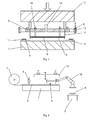
- FIG. 1 shows a schematic plan view of an exemplary plant for cutting and handling a planar blank of fiber fabric or fiber fabric for the production of components made of fiber composite material, with a cutting device and a handling device according to a preferred embodiment of the invention.
- a certain portion of a roll 2 of a fiber fabric or fiber fabric 3 to be processed is unrolled onto a punching table 1 and laid flat.
- a conventional cutting device 4 can be provided with a cutting blade mounted on a cutting bridge 9 with xy drive, which can, for example, cut out special fine patterns or otherwise supportive in the manufacturing process is involved.
- the cutting and handling device according to the invention is arranged movable between the longitudinal beams 13 of the device according to the invention.
- the corresponding cutting device is designed as a punching device with at least one punching knife 12, which the in FIG. 1 has circumferentially closed contour of the produced planar blank 6 shown.
- the integrated handling device is provided within the contour of this punching device, with an activatable holder 5 integrated therewith, which is designed such that the blank 6 cut out of the fiber fabric or fiber layer 3 in accordance with the contour can be lifted off the punching table 1 and, as in FIG FIG. 1 shown in the storage position to a draping table 7 along the longitudinal beams 13 via a traction drive 20 is movable.
- the holder 5 is shown for reasons of clarity between the two cross braces 8.
- the cross struts 8 drive between the punching table 1 above and the draping table 7 down alternately back and forth, being cut on the punching table 1 from the fiber fabric or fiber fabric 3 of the blank 6 or punched and this then by means of the holder 5 and the cross braces 8 along the VerTracksen 13 is moved over the draping table 7 and stored there.
- a draping table 7 of course, other devices can be provided which can create a three-dimensional preform from a flat blank 6, which can then be pressed to form a fiber-reinforced composite material.
- the punch press 14 (in particular the drive for this) can be arranged, for example, stationary above the punching table 1, or be connected with the transverse struts 8. In the stationary arrangement of the punch press the cutting and handling device can drive under this and be charged with the pressure for the punching stroke.
- FIG. 2 shows a more detailed, schematic sectional view of the exemplary plant for cutting and handling a planar blank of fiber fabric or fiber fabric 3 for the production of components made of fiber composite material, with a cutting device and a handling device according to the preferred embodiment of the invention according to the FIG. 1 ,
- the punching device has, as mentioned, according to the invention at least one punching knife 12, which has a corresponding contour.
- the integrated activatable holder 5 is designed as a vacuum suction device 17 with a corresponding perforated plate and connected to a vacuum line 15, wherein sucked by applying the negative pressure of the punching blade 12 punched blank to the perforated plate and thus can be lifted from the punching table 1.
- the punching table 1 carries on its upper side a cutting pad 10, which receives the punching stroke accordingly.
- moveable (liftable and lowerable and / or pivotable) and clampable hold-down devices 11 are provided, which restrain the unfolded residual material of the unrolled web of the flat fiber fabric or fiber scrim 3 on the punching table 1.
- the punching is done via a punching stroke of a punch press 14, with which the punching blade 12 is pressed against the punching table 1 and through the fiber fabric or fiber fabric 3.
- a punch press 14 with which the punching blade 12 is pressed against the punching table 1 and through the fiber fabric or fiber fabric 3.
- ejectors 16 are additionally provided, which can store the punched-out tissue contours by carrying out a stroke and simultaneous shutdown of the suction there to deposit the punched contour on a drapery table 7 or in a mold.
- the integrated activatable holder 4 may be used instead of in the form of a vacuum suction device 17 also in the form of, for example, adhesive or Venturi sucker or the like, depending on the material to be processed.
- FIG. 3 shows a schematic view from the side of an exemplary plant for cutting and handling a planar blank made of fiber fabric or fiber fabric for the production of components made of fiber composite material, with a cutting device and a handling device according to another preferred embodiment of the invention.
- FIG. 3 shows a side schematic view of the device according to the invention, in which a robot 18 for the manipulation of the punching blade 12 of the punching device and the integrated activatable holder 5 of the cutting device is preferably provided according to the invention, so that so particularly effective storage of the blanks 6 thus produced also in several layers a draping table 7 can be made.
- a robot 18 for the manipulation of the punching blade 12 of the punching device and the integrated activatable holder 5 of the cutting device is preferably provided according to the invention, so that so particularly effective storage of the blanks 6 thus produced also in several layers a draping table 7 can be made.
- a robot 18 for the manipulation of the punching blade 12 of the punching device and the integrated activatable holder 5 of the cutting device is preferably provided according to the invention, so that so particularly effective storage of the blanks 6 thus produced also in several layers a draping table 7 can be made.
- a punch press 14 for supporting the robot 18 can also be arranged here, which supports and / or carries out the punching stroke of the punching knife 12 and whereas the robot 18 is provided for the exact positioning of the punching knife 12 and the holder 5.
- the division or separation of the punching blade 12 from the punch press 14 also advantageously offers the possibility of creating different or identical blanks 6 alternately or simultaneously with several robots and separately on several or together on a draping table 7 or in one or more molding presses store.
Landscapes
- Engineering & Computer Science (AREA)
- Mechanical Engineering (AREA)
- Robotics (AREA)
- Life Sciences & Earth Sciences (AREA)
- Forests & Forestry (AREA)
- Treatment Of Fiber Materials (AREA)
Applications Claiming Priority (1)
| Application Number | Priority Date | Filing Date | Title |
|---|---|---|---|
| DE102013109857.6A DE102013109857A1 (de) | 2013-09-09 | 2013-09-09 | Vorrichtung und Verfahren zum Zuschneiden und Handhaben eines flächenhaften Zuschnittes, insbesondere zur Herstellung von Bauteilen aus Faserverbundwerkstoff |
Publications (1)
| Publication Number | Publication Date |
|---|---|
| EP2845701A1 true EP2845701A1 (fr) | 2015-03-11 |
Family
ID=51518605
Family Applications (1)
| Application Number | Title | Priority Date | Filing Date |
|---|---|---|---|
| EP14184084.3A Withdrawn EP2845701A1 (fr) | 2013-09-09 | 2014-09-09 | Dispositif et procédé de découpe et de manipulation d'une section extensive, notamment pour la fabrication de composants en matériau en fibres composites |
Country Status (2)
| Country | Link |
|---|---|
| EP (1) | EP2845701A1 (fr) |
| DE (1) | DE102013109857A1 (fr) |
Cited By (9)
| Publication number | Priority date | Publication date | Assignee | Title |
|---|---|---|---|---|
| EP2898997A3 (fr) * | 2014-01-27 | 2016-03-02 | Kabushiki Kaisha Yaskawa Denki | Système de robot, main d'aspiration avec coupeur et procédé de production de produit comprenant une pièce |
| CN108505314A (zh) * | 2018-05-07 | 2018-09-07 | 应城市天润产业用布有限责任公司 | 环形毛毯裁切装置 |
| EP3392024A1 (fr) * | 2017-04-11 | 2018-10-24 | The Boeing Company | Appareil effecteur d'extrémité multifonctions et procédés d'assemblage d'articles composites thermoplastiques |
| CN110983496A (zh) * | 2019-12-31 | 2020-04-10 | 佛山景日自动化科技有限公司 | 一种纺丝切割及夹持移动手臂 |
| US10695916B2 (en) | 2018-07-05 | 2020-06-30 | The Boeing Company | End effectors having reconfigurable vacuum heads |
| US10702993B2 (en) | 2018-07-05 | 2020-07-07 | The Boeing Company | End effectors having compaction feet for welding thermoplastic parts |
| US11052494B1 (en) | 2020-01-07 | 2021-07-06 | The Boeing Company | Methods and apparatus for semi-automated tack welding of plies of a thermoplastic composite layup |
| JP2022094451A (ja) * | 2020-12-15 | 2022-06-27 | キヤノン株式会社 | 切断装置および切断ヘッド |
| CN115262209A (zh) * | 2022-07-08 | 2022-11-01 | 晋江市宏兴服饰织造有限公司 | 一种抗菌防紫外线的泳装面料加工设备及其加工工艺 |
Families Citing this family (2)
| Publication number | Priority date | Publication date | Assignee | Title |
|---|---|---|---|---|
| DE102015116302B4 (de) | 2015-09-25 | 2025-02-27 | Deutsches Zentrum für Luft- und Raumfahrt e.V. | Niederhalter, Effektor und Verfahren zum Herstellen eines Lagenaufbaus aus flächigen thermoplastischen Faser-Matrix-Halbzeug-Lagen |
| DE102016120008A1 (de) * | 2016-10-20 | 2018-04-26 | Deutsches Zentrum für Luft- und Raumfahrt e.V. | Verfahren und Anlage zur Herstellung eines Zuschnittes aus textilen Halbzeugen |
Citations (8)
| Publication number | Priority date | Publication date | Assignee | Title |
|---|---|---|---|---|
| US5382404A (en) * | 1989-05-04 | 1995-01-17 | Murata Manufacturing Co., Ltd. | Method of cutting out a portion of a weak sheet |
| DE19515791A1 (de) * | 1995-04-28 | 1996-10-31 | Huber Anton Systemtechnik Gmbh | Vorrichtung zur Herstellung von Glasfaser-Vorformlingen aus Glasfasermatten |
| US6178861B1 (en) * | 1998-11-23 | 2001-01-30 | Semiconductor Technologies & Instruments, Inc. | Single station cutting apparatus for separating semiconductor packages |
| WO2003066493A1 (fr) * | 2002-02-08 | 2003-08-14 | Fountain Technologies B.V. | Convoyeur a emporte-piece |
| US20040168559A1 (en) * | 2003-02-28 | 2004-09-02 | Tdk Corporation | Optical recording medium-manufacturing apparatus |
| WO2005046949A1 (fr) * | 2003-11-13 | 2005-05-26 | Huhtamaki Molded Fiber Technology B.V. | Procede et dispositif de poinçonnage d'une partie de materiau en fibre moulee |
| WO2009047849A1 (fr) * | 2007-10-10 | 2009-04-16 | Beac Co., Ltd. | Dispositif de production de panneau de câblage flexible |
| DE102007061427B4 (de) | 2007-12-20 | 2009-11-12 | Airbus Deutschland Gmbh | Vorrichtung zum Zuschneiden und Handhaben eines im Wesentlichen flächenhaften Zuschnittes aus einem CFK-Halbzeug und Verfahren |
-
2013
- 2013-09-09 DE DE102013109857.6A patent/DE102013109857A1/de not_active Withdrawn
-
2014
- 2014-09-09 EP EP14184084.3A patent/EP2845701A1/fr not_active Withdrawn
Patent Citations (8)
| Publication number | Priority date | Publication date | Assignee | Title |
|---|---|---|---|---|
| US5382404A (en) * | 1989-05-04 | 1995-01-17 | Murata Manufacturing Co., Ltd. | Method of cutting out a portion of a weak sheet |
| DE19515791A1 (de) * | 1995-04-28 | 1996-10-31 | Huber Anton Systemtechnik Gmbh | Vorrichtung zur Herstellung von Glasfaser-Vorformlingen aus Glasfasermatten |
| US6178861B1 (en) * | 1998-11-23 | 2001-01-30 | Semiconductor Technologies & Instruments, Inc. | Single station cutting apparatus for separating semiconductor packages |
| WO2003066493A1 (fr) * | 2002-02-08 | 2003-08-14 | Fountain Technologies B.V. | Convoyeur a emporte-piece |
| US20040168559A1 (en) * | 2003-02-28 | 2004-09-02 | Tdk Corporation | Optical recording medium-manufacturing apparatus |
| WO2005046949A1 (fr) * | 2003-11-13 | 2005-05-26 | Huhtamaki Molded Fiber Technology B.V. | Procede et dispositif de poinçonnage d'une partie de materiau en fibre moulee |
| WO2009047849A1 (fr) * | 2007-10-10 | 2009-04-16 | Beac Co., Ltd. | Dispositif de production de panneau de câblage flexible |
| DE102007061427B4 (de) | 2007-12-20 | 2009-11-12 | Airbus Deutschland Gmbh | Vorrichtung zum Zuschneiden und Handhaben eines im Wesentlichen flächenhaften Zuschnittes aus einem CFK-Halbzeug und Verfahren |
Cited By (12)
| Publication number | Priority date | Publication date | Assignee | Title |
|---|---|---|---|---|
| EP2898997A3 (fr) * | 2014-01-27 | 2016-03-02 | Kabushiki Kaisha Yaskawa Denki | Système de robot, main d'aspiration avec coupeur et procédé de production de produit comprenant une pièce |
| EP3392024A1 (fr) * | 2017-04-11 | 2018-10-24 | The Boeing Company | Appareil effecteur d'extrémité multifonctions et procédés d'assemblage d'articles composites thermoplastiques |
| US10800110B2 (en) | 2017-04-11 | 2020-10-13 | The Boeing Company | Multifunction end effector apparatus and methods for assembling thermoplastic composite articles |
| CN108505314A (zh) * | 2018-05-07 | 2018-09-07 | 应城市天润产业用布有限责任公司 | 环形毛毯裁切装置 |
| CN108505314B (zh) * | 2018-05-07 | 2023-08-22 | 应城市天润产业用布有限责任公司 | 环形毛毯裁切装置 |
| US10695916B2 (en) | 2018-07-05 | 2020-06-30 | The Boeing Company | End effectors having reconfigurable vacuum heads |
| US10702993B2 (en) | 2018-07-05 | 2020-07-07 | The Boeing Company | End effectors having compaction feet for welding thermoplastic parts |
| CN110983496A (zh) * | 2019-12-31 | 2020-04-10 | 佛山景日自动化科技有限公司 | 一种纺丝切割及夹持移动手臂 |
| US11052494B1 (en) | 2020-01-07 | 2021-07-06 | The Boeing Company | Methods and apparatus for semi-automated tack welding of plies of a thermoplastic composite layup |
| JP2022094451A (ja) * | 2020-12-15 | 2022-06-27 | キヤノン株式会社 | 切断装置および切断ヘッド |
| CN115262209A (zh) * | 2022-07-08 | 2022-11-01 | 晋江市宏兴服饰织造有限公司 | 一种抗菌防紫外线的泳装面料加工设备及其加工工艺 |
| CN115262209B (zh) * | 2022-07-08 | 2023-11-21 | 晋江市宏兴服饰织造有限公司 | 一种抗菌防紫外线的泳装面料加工设备及其加工工艺 |
Also Published As
| Publication number | Publication date |
|---|---|
| DE102013109857A1 (de) | 2015-03-12 |
Similar Documents
| Publication | Publication Date | Title |
|---|---|---|
| EP2845701A1 (fr) | Dispositif et procédé de découpe et de manipulation d'une section extensive, notamment pour la fabrication de composants en matériau en fibres composites | |
| EP2709810B1 (fr) | Procédé et dispositif pour le transport d'un contour de fibres, découpé d'un tissu fibreux plat, au cours de la production de pièces moulées en matière plastique renforcée par des fibres | |
| EP1301322B1 (fr) | Procede et dispositif permettant la realisation de pieces en plastique en forme de coques renforcees par couche de fibres | |
| EP2969492B1 (fr) | Procédé et systèmes servant à fabriquer des composants composites innovants | |
| AT517938B1 (de) | Fertigungsanlage zum Legen von Faserbändern | |
| EP2637842A1 (fr) | Procédé et dispositif pour la fabrication d'une préforme tridimensionnelle dans le cadre de la fabrication d'éléments moulés renforcés de fibres | |
| EP2637841A1 (fr) | Procédé et dispositif pour la fabrication d'une préforme tridimensionnelle dans le cadre de la fabrication d'éléments moulés renforcés de fibres | |
| DE102010043663A1 (de) | Verfahren, Vorrichtung und Formschale zur Herstellung eines drei-dimensionalen Vorformlings im Zuge der Herstellung von faserverstärkten Formteilen | |
| DE102014003294A1 (de) | Ausbrechwerkzeug für eine Stanzmaschine | |
| WO2017129806A1 (fr) | Outil de drapage d'une découpe fibreuse et procédé de fabrication d'une ébauche tridimensionnelle | |
| DE102017121892B4 (de) | Verfahren, Vorrichtung und Verwendung einer Vorrichtung zum kontinuierlichen Handhaben und Ablegen von technischen Textilien, insbesondere in Form eines Textillagenpakets, in ein Formwerkzeug | |
| EP3380292B1 (fr) | Production de préformes à base de matière composite textile | |
| AT15267U1 (de) | Verfahren und Vorrichtung zum Besäumen eines vorgefertigten Halbzeugs | |
| DE202017105285U1 (de) | Tapelegevorrichtung mit selektiver Einschneideeinrichtung | |
| DE3620853A1 (de) | Verfahren zur loesbaren befestigung einer stanzgegenplatte an einer stanzmaschine sowie stanzmaschine | |
| DE202013104093U1 (de) | Vorrichtung zum Zuschneiden und Handhaben eines flächenhaften Zuschnittes, insbesondere zur Herstellung von Bauteilen aus Faserverbundwerkstoff | |
| DE102018201850A1 (de) | Verfahren zum Kaschieren einer Oberseite eines Trägerbauteils mit einer Kaschiermateriallage und zugehörige Vorrichtung | |
| DE102013200131B4 (de) | Automatisiertes Materialfördersystem, Materialeinbringungsanordnung und Verfahren zum Ausbilden einer Verbundstruktur | |
| DE102013001778A1 (de) | Überwachungsverfahren zur Kollisionsvermeidung einer Stanzmaschine mit Bremsbürste | |
| DE102013209270B4 (de) | Vorrichtung zum Einspannen einer Faseranordnung | |
| DE102013006348A1 (de) | Oberwerkzeug, Bearbeitungsstation und Verfahren zum Ausbrechen | |
| DE10051098B4 (de) | Vorrichtung zum Niederhalten von Stanzgut | |
| DE102018109212A1 (de) | Verfahren und Anlage zum Herstellen einer Faserpreform sowie Verfahren zur Herstellung eines Faserverbundbauteils | |
| DE10152402A1 (de) | Verfahren und Vorrichtung zum Herausarbeiten von kleinteiligen Objekten aus plattenförmigem Ausgangsmaterial | |
| WO2023099552A1 (fr) | Unité de poinçonnage dotée d'un dispositif de changement de cylindre de poinçonnage et procédé de changement d'un cylindre de poinçonnage |
Legal Events
| Date | Code | Title | Description |
|---|---|---|---|
| 17P | Request for examination filed |
Effective date: 20140909 |
|
| AK | Designated contracting states |
Kind code of ref document: A1 Designated state(s): AL AT BE BG CH CY CZ DE DK EE ES FI FR GB GR HR HU IE IS IT LI LT LU LV MC MK MT NL NO PL PT RO RS SE SI SK SM TR |
|
| AX | Request for extension of the european patent |
Extension state: BA ME |
|
| PUAI | Public reference made under article 153(3) epc to a published international application that has entered the european phase |
Free format text: ORIGINAL CODE: 0009012 |
|
| STAA | Information on the status of an ep patent application or granted ep patent |
Free format text: STATUS: THE APPLICATION IS DEEMED TO BE WITHDRAWN |
|
| 18D | Application deemed to be withdrawn |
Effective date: 20150912 |