EP2845791B1 - Bug eines Schlauchboots - Google Patents
Bug eines Schlauchboots Download PDFInfo
- Publication number
- EP2845791B1 EP2845791B1 EP14183197.4A EP14183197A EP2845791B1 EP 2845791 B1 EP2845791 B1 EP 2845791B1 EP 14183197 A EP14183197 A EP 14183197A EP 2845791 B1 EP2845791 B1 EP 2845791B1
- Authority
- EP
- European Patent Office
- Prior art keywords
- inflatable
- boat
- end portions
- floor
- bow
- Prior art date
- Legal status (The legal status is an assumption and is not a legal conclusion. Google has not performed a legal analysis and makes no representation as to the accuracy of the status listed.)
- Not-in-force
Links
- 239000000463 material Substances 0.000 claims description 4
- 239000004753 textile Substances 0.000 claims description 3
- 239000011324 bead Substances 0.000 description 3
- 238000012423 maintenance Methods 0.000 description 3
- 240000005561 Musa balbisiana Species 0.000 description 1
- 235000018290 Musa x paradisiaca Nutrition 0.000 description 1
- 230000000694 effects Effects 0.000 description 1
- 239000012530 fluid Substances 0.000 description 1
- 230000001737 promoting effect Effects 0.000 description 1
- 229910000679 solder Inorganic materials 0.000 description 1
- XLYOFNOQVPJJNP-UHFFFAOYSA-N water Substances O XLYOFNOQVPJJNP-UHFFFAOYSA-N 0.000 description 1
- 238000003466 welding Methods 0.000 description 1
Images


Classifications
-
- B—PERFORMING OPERATIONS; TRANSPORTING
- B63—SHIPS OR OTHER WATERBORNE VESSELS; RELATED EQUIPMENT
- B63B—SHIPS OR OTHER WATERBORNE VESSELS; EQUIPMENT FOR SHIPPING
- B63B7/00—Collapsible, foldable, inflatable or like vessels
- B63B7/06—Collapsible, foldable, inflatable or like vessels having parts of non-rigid material
- B63B7/08—Inflatable
-
- B—PERFORMING OPERATIONS; TRANSPORTING
- B63—SHIPS OR OTHER WATERBORNE VESSELS; RELATED EQUIPMENT
- B63B—SHIPS OR OTHER WATERBORNE VESSELS; EQUIPMENT FOR SHIPPING
- B63B5/00—Hulls characterised by their construction of non-metallic material
- B63B5/24—Hulls characterised by their construction of non-metallic material made predominantly of plastics
Definitions
- the present invention relates to the field of boating, and more particularly that of inflatable boats.
- the invention relates in particular, but not exclusively, to an inflatable boat of the kayak, canoe, boat or any other type of boat.
- the first bow is preferably located at the bow of the boat.
- the invention also covers a boat that can sail in both directions so that the first bow can also be arranged at the stern of the boat in the direction of navigation of the boat.
- the bow of such an inflatable boat is constituted by the front ends of the lateral flanges which come into contact with each other in order to have an arcuate shape surrounding the front end of the inflatable bottom, which is welded to the side rolls.
- the inflatable bottom which forms the floor of the boat, is generally set back from the end of the boat while projecting below the waterline. There is a stall between the front of the floor and the rods, which has the effect of generating a very large draft, which penalizes the advance of the boat and which affects the quality of the slide of the boat. Since the floor is located below the waterline, considerable energy must be deployed by the user to move the boat forward. This type of boat has a hydrodynamic profile that is not efficient.
- An object of the invention is to provide an inflatable boat that overcomes the aforementioned drawbacks, having a better hydrodynamic profile than that of the craft of the prior art, thus providing a better quality of sliding on the water.
- the inflatable bottom comprises a floor portion, and at least a first pair of end portions extending from one of the two longitudinal ends of the floor portion; a fold line is formed between the floor portion and each of the end portions of the first pair, and when the inflatable bottom is in its inflated state, each end portion is in a folded position about the corresponding fold to form the bow of the boat.
- the inflatable bottom of the boat according to the invention forms both the floor of the boat and the bow. It is thus understood that the bow is formed by folding the two end portions along the fold lines, and this after inflating the inflatable bottom, so as to bring them against each other.
- the two end portions then extend in two inclined planes with respect to each other, and also with respect to the plane in which the floor portion extends. This increase in volume makes it possible to quickly form the first bow of the boat.
- the first bow has a pointed volume form having a hydrodynamic resistance substantially lower than that of the craft of the prior art.
- the two end portions are symmetrical to one another with respect to a longitudinal plane perpendicular to the floor portion.
- the end portions are preferably in fluid communication with the floor portion so that inflation of the inflatable bottom causes concomitant inflation of the floor portion and end portions.
- the lateral flanges are separate patches of the inflatable bottom.
- the floor portion has longitudinal side sides on either side of which extend the lateral flanges.
- the fold lines extend forming a "V" at the longitudinal end of the floor portion, the tip of the "V” being directed in a direction opposite to the other longitudinal end of the floor portion.
- the tip of the V is directed towards the end of the boat where the first bow is located.
- the fold lines are preferably rectilinear but that they could also be curved.
- These fold lines are inclined relative to the longitudinal direction of the boat. They are preferably symmetrical to one another with respect to a longitudinal median plane of the floor portion.
- the fold lines form between them an angle, considered on the side of the floor portion, between about 30 ° and 120 °.
- These lateral sides of the floor portion are substantially straight and extend from the ends of the fold lines.
- Each of the end portions has a first edge, and, preferably, the first edges of the two end portions are affixed to each other, at least when the inflatable bottom is inflated.
- the first edge extends from the tip of the "V" formed by the fold lines.
- the first edges of the end portions are free to define a notch when the inflatable bottom is deflated and unfolded
- each first edge has a rectilinear shape or, more preferably, convex. An interest in the convex shape and improve the hydrodynamic profile of the bow of the boat.
- Each of the end portions further has a second edge which extends between the end of one of the lateral sides of the floor portion and the end of the first edge remote from the end of the floor portion.
- This second edge advantageously has a convex shape, which makes it possible to increase the volume of the stem.
- the inflatable lateral strands have a curved shape so that when the inflatable lateral strands and the inflatable bottom are inflated, the end portions extend below the longitudinal ends of the inflatable lateral struts.
- lateral flanges extend parallel to the lateral sides of the floor portion.
- the inflatable lateral strands and the inflatable bottom are inflated, the inflatable lateral strands rest on the end portions. More specifically, the longitudinal ends of the inflatable lateral strands rest at least in part on the second edges of the end portions.
- the second edges of the end portions, in folded position are arranged on either side of the two lateral flanges, so that the longitudinal ends of the lateral flanges are arranged inside the first bow.
- the longitudinal ends of the lateral flanges have, at the level of the floor portion, a cross section greater than that existing at the longitudinal ends.
- the end portions comprise discontinuous weld lines delimiting a plurality of strands.
- An interest is that, in their deflated state, the end portions are flat, and easily manipulated for storage.
- each end portion Preferably, for each end portion, the flanges are parallel to each other.
- each end portion preferably comprises between four and seven strands.
- the floor portion has a plurality of continuous weld lines that extend a length slightly less than the length of the floor portion. These flanges are set volume during inflation of the inflatable bottom.
- the fold line is a discontinuous weld, whereby the floor portion and the end portions are inflated together, which allows rapid assembly of the boat.
- the inflatable bottom comprises at least one inflation valve disposed at at least one of the two longitudinal ends of the floor portion.
- the inflation valve is more particularly disposed near the tip of the "V" formed by the fold lines.
- each of the lateral flanges are inflated independently of one another, and independently of the inflatable bottom.
- each side flange comprises an inflation valve. The lateral flanges are therefore fluidly isolated from the inflatable bottom.
- the boat further comprises an outer casing in which the inflatable lateral tubes and the inflatable bottom are housed.
- the outer shell extends over all or part of the length of the boat.
- the floor portion is engaged in a cover to be fixed to the outer casing.
- the inflatable bottom and / or the inflatable lateral flanges consist of a layer of PVC covered with a textile layer.
- the inflatable bottom and / or the inflatable lateral socks are made of a coated material, for example PU.
- the inflatable bottom is welded to the inflatable lateral socks. In this embodiment, it is possible to dispense with an outer envelope.
- the inflatable bottom further comprises a second pair of end portions extending from the other longitudinal end of the floor portion, and the end portions of the second pair are arranged to be folded relative to each other. at the floor portion to form a second bow of the boat, opposite the first bow, when the inflatable bottom is in its inflated state.
- the first bow is located at the bow of the boat, while the second bow is located at the stern of the boat.
- the first and second bows are symmetrical to one another with respect to a plane perpendicular to the longitudinal direction of the boat.
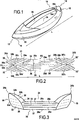
- an inflatable boat 10 according to the present invention.
- it is a boat type canoe or kayak.
- the boat 10 extends in a longitudinal direction L, and conventionally has a front part called bow, referenced 12, and a rear part, called stern, referenced 14.
- the bow 12 has a first bow 16 which will be described in more detail below.
- the stern 14 has substantially the same shape as the bow 12, so that the stern 14 also has a bow, called second bow 18, opposite the first bow.
- the boat 10 furthermore comprises two inflatable lateral rollers 20, 22 which extend in the longitudinal direction L of the boat 10, between the bow 12 and the stern 14.
- the length of the inflatable lateral rods is substantially equal to the length of the boat.
- Each of the lateral tubes 20, 22 has a substantially circular cross section.
- Each side bead has a curved shape.
- each inflatable lateral bead 20, 22 has a longitudinal end before 20a, 22a, and a rear longitudinal end 20b, 22b.
- the cross sections of the lateral flanges are smaller at the longitudinal ends than in the middle of the flanges. More specifically, the cross sections of the flanges decrease towards the longitudinal ends.
- each side coil 20, 22 is equipped with an inflation valve 20c disposed in this example near the rear longitudinal end.
- the inflatable longitudinal beads are fluidly independent of each other. This means that they can be inflated and deflated independently of each other.
- the boat 10 further comprises an inflatable bottom 24 which extends in the longitudinal direction of the lateral flanges while being disposed between said two lateral flanges 20, 22.
- the inflatable bottom 24 and the inflatable lateral strands 20, 22 consist of a layer of PVC covered with a textile layer. They could however be made of a coated material, for example PU.
- FIG 2 represents the inflatable bottom, in its deflated state.
- the inflatable bottom extends substantially plane. It has a front portion 24a and a rear portion 24b.
- the inflatable bottom 24 further comprises a floor portion, referenced 26, which has a longitudinal end before 26a and a rear longitudinal end 26b.
- the floor portion 26 constitutes the floor of the boat 10.
- the lateral flanges 20, 22 extend on either side of the lateral sides of the floor portion 26.
- the lateral flanges 20, 22 are separate patches of the inflatable bottom 24.
- the inflatable bottom 24 further comprises a first pair of end portions 30, 32 which extend from the longitudinal end before 26a of the floor portion.
- these two end portions 30, 32 are symmetrical to one another with respect to a plane P1 which extends in the longitudinal direction L while being orthogonal to the floor portion 26.
- the end portions 30, 32 are preferably made of the same material as the floor portion 26.
- the end portions 30, 32 are also connected to the floor portion along fold lines 34, 36 formed between the floor portion and each of the end portions.
- the fold lines 34, 36 are inclined with respect to the longitudinal direction of the boat. In this embodiment, they form substantially a "V" at the longitudinal end 26a of the floor portion.
- the tip of the "V” is directed in a direction opposite to the other longitudinal end 26b of the floor portion. In other words, the tip of the "V” is directed towards the front end 24a of the inflatable bottom 24.
- the fold lines 34, 36 are constituted by discontinuous welds, which makes it possible simultaneously to inflate the end portions and the floor portion.
- each of the end portions 30, 32 has first edges respectively referenced 30a and 32a, the first edges of the two end portions of the first pair being disposed opposite each other. 'other.
- the first edges 30a, 32a are convex.
- Each of the end portions 30, 32 further includes a second edge 30b, 32b, also convex.
- Each first edge 30a, 32a extends between the tip 26d of the "V" formed by the fold lines 34, 36, and a first end of the second edge 30b, 32b, the second end of said second edge 30b, 32b corresponds to front end of the lateral side 26c, 26d corresponding.
- first and second edges 30a, 32a, 30b, 32b may form a single curved line.
- first second edges are the edges which extend on either side of the front vertex of said curved line.
- the inflatable bottom 2624 further comprises a second pair of end portions 30 ', 32' which extend from the rear longitudinal end 26b of the floor portion 26.
- the end portions 30 ', 32' of the second pair are symmetrical to the end portions 30, 32 of the first pair with respect to a plane P2 perpendicular to the longitudinal direction L and perpendicular to the plane in which the floor portion extends.
- the inflatable bottom 26 also comprises fold lines 34 ', 36' which connect the floor format portion to the end portions 30 ', 32'.
- the floor portion 26 further comprises a plurality of continuous weld lines 26e which are parallel to each other and which extend in the longitudinal direction L. These continuous weld lines 26e extend between the fold lines 34, 36 of the end portions of the first pair and fold lines 34 ', 36' of the end portions of the second pair being slightly recessed relative thereto in order to provide passages for air. It is therefore understood that, in its inflated state, the floor portion comprises a plurality of parallel flanges 27 delimited from each other by the weld lines 26e.
- the end portions 30, 32, 30 ', 32' also comprise discontinuous solder lines 30e, 32e, 30'e, 32'e parallel to each other and parallel to the associated fold line, so that when the inflatable bottom is inflated, the end portions have flanges demarcated from each other by discontinuous welds 30e, 32e, 30'e, 32'e.
- the figure 3 illustrates the inflatable bottom 24 in its inflated state.
- the inflatable bottom has an inflation valve 24c, better visible on the figure 5 which is located near the tip of the "V" formed by the fold lines 34 ', 36' of the end portions of the second pair.
- the fold lines 34 ', 36' are constituted by discontinuous welds, which allows rapid and simultaneous inflation of the floor portion and end portions 30, 32.
- each end portion 30, 32 of the first pair can be folded around the corresponding fold line 34, 36 to form the first bow 16 of the boat .
- the end portions 30 ', 32' of the second pair may be folded around the fold lines 34 ', 36' corresponding to form the second bow 18 of the boat.
- the width of the inflatable bottom, in its inflated state corresponds to the width I of the floor portion 26.
- first bow 16 formed by the folding of the end portions 30, 32 in the fold lines 34, 36 is represented more particularly. It is understood that the first edges 30a, 32a are brought against each other in order to to form the front end edge of the stem 16. In this example, the upper portions of the first edges 30, 32 are fixed to each other, in this example, by welding, to improve the maintenance of the first bow 16.
- the floor portion 26 is preferably engaged in a cover 40 illustrated on the Figures 6a and 6b .
- the cover 40 engages the floor portion, the end portions of the first and second pairs extending out of the cover on either side of these longitudinal ends.
- the inflatable bottom and the lateral flanges are inflated with the aid of an inflator connected to the inflation valves.
- the end portions 30, 32, 30 ', 32' are folded around their respective fold lines 34, 36, 34 ', 36' to form the first and second bows 16, 18.
- the inflatable bottom and the lateral flanges are then arranged together in such a way that the lateral flanges extend on either side of the lateral sides of the floor portion.
- the end portions forming the first and second bows 16, 18 are then arranged to extend below the longitudinal ends 20a, 22a, 20b, 22b of the inflatable lateral tubes 20, 22.
- This provision is favored by the As mentioned above, the lateral strands 20, 22 have a curved shape, a kind of "banana" shape. It is therefore understood that the first bow 16 is disposed under the longitudinal ends of the lateral tubes 20, 22.
- the figure 8 which represents the bow 16 seen in cross section, illustrates that the flanges 20, 22 rest on the end portions 30, 32. It is understood by means of this figure 8 that the cross section of the bow 16 having a hydrodynamic profile promoting sliding. On this figure 8 we also illustrated the waterline E.
- the boat 10 further comprises an outer casing 50 in which the lateral flanges 20, 22 and the inflatable bottom are housed.
- the cover 40 is preferably attached to the outer casing 50.
- the outer casing 50 extends over the entire length of the boat 10.
- the inflatable bottom may be welded to the lateral flanges 20, 22 to further improve the robustness of the boat 10.
Landscapes
- Chemical & Material Sciences (AREA)
- Engineering & Computer Science (AREA)
- Combustion & Propulsion (AREA)
- Mechanical Engineering (AREA)
- Ocean & Marine Engineering (AREA)
- Air Bags (AREA)
- Toys (AREA)
- Tents Or Canopies (AREA)
- Refuge Islands, Traffic Blockers, Or Guard Fence (AREA)
- Professional, Industrial, Or Sporting Protective Garments (AREA)
Claims (15)
- Wasserfahrzeug (10), das eine Längsrichtung (L) aufweist und umfasst:- einen ersten Bug (16),- zwei aufblasbare seitliche Schlauchhüllen (20, 22), die sich in Längsrichtung des Wasserfahrzeugs erstrecken,- eine aufblasbare Basis (24), die zwischen den beiden aufblasbaren seitlichen Schlauchhüllen (20, 22) angeordnet ist,wobei das Wasserfahrzeug dadurch gekennzeichnet ist, dass die aufblasbare Basis (24) einen einen Boden (26) bildenden Abschnitt und mindestens ein erstes Paar von Endabschnitten (30, 31, 30', 32') umfasst, die sich von einem der beiden Längsenden (26a, 26b) des einen Boden bildenden Abschnitts aus erstrecken, dass eine Falzlinie (34, 36, 34', 36') zwischen dem einen Boden bildenden Abschnitt und jedem der Endabschnitte des ersten Paars gebildet ist, und dass, wenn sich die aufblasbare Basis (24) in ihrem aufgeblasenen Zustand befindet, jeder Endabschnitt ein einer gefalzten Position um die entsprechende Falzlinie ist, um den ersten Bug (16) des Wasserfahrzeugs zu bilden.
- Wasserfahrzeug nach Anspruch 1, dadurch gekennzeichnet, dass sich die Falzlinien (34) unter Bildung eines "V" an einem der Längsenden (26a) des einen Boden bildenden Abschnitts erstrecken, wobei die Spitze (26d) des "V" in eine entgegengesetzte Richtung zum anderen Längsende (26b) des einen Boden bildenden Abschnitts gerichtet ist.
- Wasserfahrzeug nach Anspruch 1 oder 2, dadurch gekennzeichnet, dass jeder der Endabschnitte (30, 32) einen ersten Rand (30a, 32a) aufweist, und dass die ersten Ränder der beiden Endabschnitte aneinander befestigt sind, zumindest wenn die aufblasbare Basis aufgeblasen ist.
- Wasserfahrzeug nach einem der Ansprüche 1 bis 3, dadurch gekennzeichnet, dass die aufblasbaren seitlichen Schlauchhüllen (20, 22) eine gekrümmte Form aufweisen, so dass, wenn die aufblasbaren seitlichen Schlauchhüllen (20, 22) und die aufblasbare Basis (24) aufgeblasen werden, sich die Endabschnitte, die den Bug bilden, unter den Längsenden (20a, 22a, 20b, 22b) der aufblasbaren seitlichen Schlauchhüllen (20, 22) erstrecken.
- Wasserfahrzeug nach Anspruch 4, dadurch gekennzeichnet, dass, wenn die aufblasbaren seitlichen Schlauchhüllen (20, 22) und die aufblasbare Basis (24) aufgeblasen sind, die aufblasbaren seitlichen Schlauchhüllen (20, 22) auf den Endabschnitten liegen.
- Wasserfahrzeug nach einem der Ansprüche 1 bis 5, dadurch gekennzeichnet, dass die Endabschnitte (30, 32, 30', 32') diskontinuierliche Schweißlinien (30e, 32e, 30'c, 32'e) umfassen, die eine Vielzahl von Schlauchhüllen begrenzen.
- Wasserfahrzeug nach einem der Ansprüche 1 bis 6, dadurch gekennzeichnet, dass die Falzlinie (34, 36, 34', 36') eine diskontinuierliche Schweißnaht ist.
- Wasserfahrzeug nach einem der Ansprüche 1 bis 7, dadurch gekennzeichnet, dass die aufblasbare Basis (24) mindestens ein Aufblasventil (24c) umfasst, das an einem der Längsenden des einen Boden bildenden Abschnitts angeordnet ist.
- Wasserfahrzeug nach einem der Ansprüche 1 bis 8, dadurch gekennzeichnet, dass es ferner eine äußere Hülle (50) umfasst, in der die aufblasbaren seitlichen Schlauchhüllen (20, 22) und die aufblasbare Basis (24) angeordnet sind.
- Wasserfahrzeug nach Anspruch 9, dadurch gekennzeichnet, dass sich die äußere Hülle (50) auf der Gesamtheit oder einem Teil der Länge des Wasserfahrzeugs (10) erstreckt.
- Wasserfahrzeug nach Anspruch 10, dadurch gekennzeichnet, dass der einen Boden bildende Abschnitt in einer Schutzhülle (40) in Eingriff ist, die dazu bestimmt ist, an der äußeren Hülle (50) befestigt zu werden.
- Wasserfahrzeug nach einem der Ansprüche 1 bis 11, dadurch gekennzeichnet, dass die aufblasbare Basis (24) und/oder die aufblasbaren seitlichen Schlauchhüllen (20, 22) aus einer PVC-Schicht, die mit einer Textilschicht überzogen ist, bestehen.
- Wasserfahrzeug nach einem der Ansprüche 1 bis 12, dadurch gekennzeichnet, dass die aufblasbare Basis (24) und/oder die aufblasbaren seitlichen Schlauchhüllen (20, 22) aus einem beschichteten Material, beispielsweise PU, hergestellt sind.
- Wasserfahrzeug nach einem der Ansprüche 1 bis 13, dadurch gekennzeichnet, dass die aufblasbare Basis (24) an die aufblasbaren seitlichen Schlauchhüllen (20, 22) geschweißt ist.
- Wasserfahrzeug nach einem der Ansprüche 1 bis 14, dadurch gekennzeichnet, dass die aufblasbare Basis (24) ferner ein zweites Paar von Endabschnitten (30', 32') umfasst, die sich vom anderen Längsende (26b) des einen Boden bildenden Abschnitts aus erstrecken, und dass die Endabschnitte des zweiten Paars derart angeordnet sind, dass sie in Bezug zu dem einen Boden bildenden Abschnitt gefalzt werden, um einen zweiten Bug (18) des Wasserfahrzeugs, der dem ersten Bug entgegengesetzt ist, zu bilden, wenn sich die aufblasbaren seitlichen Schlauchhüllen und die aufblasbare Basis in ihrem aufgeblasenen Zustand befinden.
Applications Claiming Priority (1)
| Application Number | Priority Date | Filing Date | Title |
|---|---|---|---|
| FR1358532A FR3010043B1 (fr) | 2013-09-05 | 2013-09-05 | Etrave de bateau gonflable |
Publications (2)
| Publication Number | Publication Date |
|---|---|
| EP2845791A1 EP2845791A1 (de) | 2015-03-11 |
| EP2845791B1 true EP2845791B1 (de) | 2016-04-06 |
Family
ID=49911636
Family Applications (1)
| Application Number | Title | Priority Date | Filing Date |
|---|---|---|---|
| EP14183197.4A Not-in-force EP2845791B1 (de) | 2013-09-05 | 2014-09-02 | Bug eines Schlauchboots |
Country Status (7)
| Country | Link |
|---|---|
| US (1) | US20150059635A1 (de) |
| EP (1) | EP2845791B1 (de) |
| CN (1) | CN104417712B (de) |
| BR (1) | BR102014021918A2 (de) |
| ES (1) | ES2580045T3 (de) |
| FR (1) | FR3010043B1 (de) |
| RU (1) | RU2587305C2 (de) |
Families Citing this family (6)
| Publication number | Priority date | Publication date | Assignee | Title |
|---|---|---|---|---|
| RU2628278C1 (ru) * | 2016-04-25 | 2017-08-15 | Игорь Юрьевич Киселев | Надувной гидроцикл со стационарным транцем для подвесного мотора |
| US11267544B2 (en) | 2020-03-17 | 2022-03-08 | Honda Motor Co., Ltd. | Stabilization system for marine vessels |
| CN111547195B (zh) * | 2020-06-10 | 2025-03-07 | 江苏吉龙运动休闲用品有限公司 | 一种充气独木舟 |
| FR3125013B1 (fr) * | 2021-07-08 | 2024-05-31 | Vanoise Jean Luc | Embarcation gonflable notamment de type canot et procédé de fabrication de ladite embarcation. |
| WO2023193199A1 (zh) * | 2022-04-07 | 2023-10-12 | 威海荣创海洋科技有限公司 | 一种四气囊充气船 |
| CN219904645U (zh) * | 2023-05-17 | 2023-10-27 | 上海荣威塑胶工业有限公司 | 一种充气产品 |
Family Cites Families (11)
| Publication number | Priority date | Publication date | Assignee | Title |
|---|---|---|---|---|
| US2873459A (en) * | 1955-01-21 | 1959-02-17 | Metzeler Gummiwerke Ag | Inflatable boat |
| FR1264327A (fr) * | 1960-08-03 | 1961-06-19 | Metzeler Gummiwerke Ag | Bateau gonflable |
| BE1000727A3 (fr) * | 1987-07-10 | 1989-03-21 | Wittamer Roger | Embarcation pliable realisee en materiaux rigides. |
| US5564357A (en) * | 1994-01-18 | 1996-10-15 | Peterson; Leroy L. | Inflatable boat protective cover |
| DE9414255U1 (de) * | 1994-09-02 | 1994-11-03 | Voigtländer, Sven, 80799 München | Aufblasbarer, schwimmfähiger Hohlkörper |
| FR2732945B1 (fr) * | 1995-04-14 | 1997-06-13 | Zodiac Int | Embarcation pneumatique fonctionnant en catamaran, a stabilite amelioree |
| FR2871433B1 (fr) * | 2004-06-11 | 2006-09-22 | Zodiac Internat Soc Par Action | Embarcation pneumatique a quille gonflable sous haute pression |
| US7322309B2 (en) * | 2006-03-30 | 2008-01-29 | Nautic & Art Inc. | Inflatable structure |
| CN101712370B (zh) * | 2009-12-18 | 2013-09-25 | 大连朝阳艇业有限公司 | 充气式艇用地板 |
| CN201737133U (zh) * | 2010-07-07 | 2011-02-09 | 李力 | 可折叠硬壳船 |
| CN102514685A (zh) * | 2011-12-14 | 2012-06-27 | 苏州市吴中区甪直荣华印花厂 | 折叠船 |
-
2013
- 2013-09-05 FR FR1358532A patent/FR3010043B1/fr not_active Expired - Fee Related
-
2014
- 2014-08-28 US US14/470,956 patent/US20150059635A1/en not_active Abandoned
- 2014-09-02 ES ES14183197.4T patent/ES2580045T3/es active Active
- 2014-09-02 EP EP14183197.4A patent/EP2845791B1/de not_active Not-in-force
- 2014-09-04 BR BR102014021918A patent/BR102014021918A2/pt not_active IP Right Cessation
- 2014-09-04 CN CN201410448717.2A patent/CN104417712B/zh not_active Expired - Fee Related
- 2014-09-04 RU RU2014136153/11A patent/RU2587305C2/ru not_active IP Right Cessation
Also Published As
| Publication number | Publication date |
|---|---|
| FR3010043B1 (fr) | 2015-09-18 |
| RU2014136153A (ru) | 2016-04-10 |
| EP2845791A1 (de) | 2015-03-11 |
| US20150059635A1 (en) | 2015-03-05 |
| ES2580045T3 (es) | 2016-08-18 |
| FR3010043A1 (fr) | 2015-03-06 |
| RU2587305C2 (ru) | 2016-06-20 |
| BR102014021918A2 (pt) | 2016-03-22 |
| CN104417712B (zh) | 2017-05-03 |
| CN104417712A (zh) | 2015-03-18 |
Similar Documents
| Publication | Publication Date | Title |
|---|---|---|
| EP2845791A1 (de) | Bug eines Schlauchboots | |
| EP2768723B1 (de) | Aufblasbarer bootskörper und schwimmendes fahrzeug, insbesondere ein schlauchboot | |
| WO2016034814A1 (fr) | Aile portante escamotable | |
| FR2871433A1 (fr) | Embarcation pneumatique a quille gonflable sous haute pression | |
| LU80221A1 (fr) | Pneumatique comprenant une structure rapportee de roulement a plat | |
| WO2019215409A1 (fr) | Embarcation gonflable de type kayak | |
| CA2805077C (fr) | Bateaux avec bordes gonflables | |
| EP2110277B1 (de) | Kraftfahrzeug mit vier Rädern, drei Sitze und seitliche Schiebetüre | |
| FR2978115A1 (fr) | Planche gonflable | |
| CA2919579C (fr) | Embarcation pneumatque a carene en v et volets | |
| EP2697113B1 (de) | Einziehbarer schifsskiel | |
| FR3090568A1 (fr) | Défense d’accostage pour navire, notamment équipée d’une plateforme d’accès à la mer. | |
| EP4367012A1 (de) | Aufblasbares fahrzeug, insbesondere vom kanonentyp, und verfahren zur herstellung dieses fahrzeugs | |
| FR3036372A1 (fr) | Embarcation pneumatique, avantageusement du type canot, annexe ou bateau | |
| CA3079577A1 (fr) | Bateau comportant un support gonflable | |
| FR2538773A1 (fr) | Canot pneumatique semi-rigide | |
| EP0298945A1 (de) | Aus starren Materialien hergestelltes faltbares Boot | |
| FR3061881A1 (fr) | Element de centrage d'un isolant de tablier relativement a une colonne de direction d'un vehicule | |
| FR3115443A1 (fr) | sac définissant un espace de stockage à volume variable | |
| FR2833238A1 (fr) | Bateau multicoques de type hydroptere a foils repliables | |
| FR3154976A1 (fr) | Embarcation gonflable de type kayak | |
| WO2016193563A1 (fr) | Chape deformable plastiquement pour le montage d'une roue de vehicule automobile | |
| FR3143005A1 (fr) | Aéronef comprenant au moins un aérofrein présentant au moins deux parties mobiles entre elles | |
| FR2946314A1 (fr) | Chaland de transport de materiel roulant | |
| FR2935950A1 (fr) | Vehicules automobiles a quatre roue. |
Legal Events
| Date | Code | Title | Description |
|---|---|---|---|
| 17P | Request for examination filed |
Effective date: 20140902 |
|
| AK | Designated contracting states |
Kind code of ref document: A1 Designated state(s): AL AT BE BG CH CY CZ DE DK EE ES FI FR GB GR HR HU IE IS IT LI LT LU LV MC MK MT NL NO PL PT RO RS SE SI SK SM TR |
|
| AX | Request for extension of the european patent |
Extension state: BA ME |
|
| PUAI | Public reference made under article 153(3) epc to a published international application that has entered the european phase |
Free format text: ORIGINAL CODE: 0009012 |
|
| R17P | Request for examination filed (corrected) |
Effective date: 20150602 |
|
| RBV | Designated contracting states (corrected) |
Designated state(s): AL AT BE BG CH CY CZ DE DK EE ES FI FR GB GR HR HU IE IS IT LI LT LU LV MC MK MT NL NO PL PT RO RS SE SI SK SM TR |
|
| GRAP | Despatch of communication of intention to grant a patent |
Free format text: ORIGINAL CODE: EPIDOSNIGR1 |
|
| RIC1 | Information provided on ipc code assigned before grant |
Ipc: B63B 7/08 20060101AFI20151014BHEP Ipc: B63B 35/71 20060101ALI20151014BHEP |
|
| INTG | Intention to grant announced |
Effective date: 20151027 |
|
| GRAS | Grant fee paid |
Free format text: ORIGINAL CODE: EPIDOSNIGR3 |
|
| GRAA | (expected) grant |
Free format text: ORIGINAL CODE: 0009210 |
|
| AK | Designated contracting states |
Kind code of ref document: B1 Designated state(s): AL AT BE BG CH CY CZ DE DK EE ES FI FR GB GR HR HU IE IS IT LI LT LU LV MC MK MT NL NO PL PT RO RS SE SI SK SM TR |
|
| REG | Reference to a national code |
Ref country code: GB Ref legal event code: FG4D Free format text: NOT ENGLISH |
|
| REG | Reference to a national code |
Ref country code: AT Ref legal event code: REF Ref document number: 787472 Country of ref document: AT Kind code of ref document: T Effective date: 20160415 Ref country code: CH Ref legal event code: EP |
|
| REG | Reference to a national code |
Ref country code: IE Ref legal event code: FG4D Free format text: LANGUAGE OF EP DOCUMENT: FRENCH |
|
| REG | Reference to a national code |
Ref country code: DE Ref legal event code: R096 Ref document number: 602014001409 Country of ref document: DE |
|
| REG | Reference to a national code |
Ref country code: LT Ref legal event code: MG4D Ref country code: NL Ref legal event code: MP Effective date: 20160406 |
|
| REG | Reference to a national code |
Ref country code: AT Ref legal event code: MK05 Ref document number: 787472 Country of ref document: AT Kind code of ref document: T Effective date: 20160406 |
|
| REG | Reference to a national code |
Ref country code: ES Ref legal event code: FG2A Ref document number: 2580045 Country of ref document: ES Kind code of ref document: T3 Effective date: 20160818 |
|
| REG | Reference to a national code |
Ref country code: FR Ref legal event code: PLFP Year of fee payment: 3 |
|
| PG25 | Lapsed in a contracting state [announced via postgrant information from national office to epo] |
Ref country code: NL Free format text: LAPSE BECAUSE OF FAILURE TO SUBMIT A TRANSLATION OF THE DESCRIPTION OR TO PAY THE FEE WITHIN THE PRESCRIBED TIME-LIMIT Effective date: 20160406 |
|
| PG25 | Lapsed in a contracting state [announced via postgrant information from national office to epo] |
Ref country code: NO Free format text: LAPSE BECAUSE OF FAILURE TO SUBMIT A TRANSLATION OF THE DESCRIPTION OR TO PAY THE FEE WITHIN THE PRESCRIBED TIME-LIMIT Effective date: 20160706 Ref country code: LT Free format text: LAPSE BECAUSE OF FAILURE TO SUBMIT A TRANSLATION OF THE DESCRIPTION OR TO PAY THE FEE WITHIN THE PRESCRIBED TIME-LIMIT Effective date: 20160406 Ref country code: PL Free format text: LAPSE BECAUSE OF FAILURE TO SUBMIT A TRANSLATION OF THE DESCRIPTION OR TO PAY THE FEE WITHIN THE PRESCRIBED TIME-LIMIT Effective date: 20160406 Ref country code: IS Free format text: LAPSE BECAUSE OF FAILURE TO SUBMIT A TRANSLATION OF THE DESCRIPTION OR TO PAY THE FEE WITHIN THE PRESCRIBED TIME-LIMIT Effective date: 20160806 Ref country code: FI Free format text: LAPSE BECAUSE OF FAILURE TO SUBMIT A TRANSLATION OF THE DESCRIPTION OR TO PAY THE FEE WITHIN THE PRESCRIBED TIME-LIMIT Effective date: 20160406 |
|
| PG25 | Lapsed in a contracting state [announced via postgrant information from national office to epo] |
Ref country code: SE Free format text: LAPSE BECAUSE OF FAILURE TO SUBMIT A TRANSLATION OF THE DESCRIPTION OR TO PAY THE FEE WITHIN THE PRESCRIBED TIME-LIMIT Effective date: 20160406 Ref country code: PT Free format text: LAPSE BECAUSE OF FAILURE TO SUBMIT A TRANSLATION OF THE DESCRIPTION OR TO PAY THE FEE WITHIN THE PRESCRIBED TIME-LIMIT Effective date: 20160808 Ref country code: HR Free format text: LAPSE BECAUSE OF FAILURE TO SUBMIT A TRANSLATION OF THE DESCRIPTION OR TO PAY THE FEE WITHIN THE PRESCRIBED TIME-LIMIT Effective date: 20160406 Ref country code: LV Free format text: LAPSE BECAUSE OF FAILURE TO SUBMIT A TRANSLATION OF THE DESCRIPTION OR TO PAY THE FEE WITHIN THE PRESCRIBED TIME-LIMIT Effective date: 20160406 Ref country code: GR Free format text: LAPSE BECAUSE OF FAILURE TO SUBMIT A TRANSLATION OF THE DESCRIPTION OR TO PAY THE FEE WITHIN THE PRESCRIBED TIME-LIMIT Effective date: 20160707 Ref country code: AT Free format text: LAPSE BECAUSE OF FAILURE TO SUBMIT A TRANSLATION OF THE DESCRIPTION OR TO PAY THE FEE WITHIN THE PRESCRIBED TIME-LIMIT Effective date: 20160406 Ref country code: RS Free format text: LAPSE BECAUSE OF FAILURE TO SUBMIT A TRANSLATION OF THE DESCRIPTION OR TO PAY THE FEE WITHIN THE PRESCRIBED TIME-LIMIT Effective date: 20160406 |
|
| REG | Reference to a national code |
Ref country code: DE Ref legal event code: R097 Ref document number: 602014001409 Country of ref document: DE |
|
| PG25 | Lapsed in a contracting state [announced via postgrant information from national office to epo] |
Ref country code: SK Free format text: LAPSE BECAUSE OF FAILURE TO SUBMIT A TRANSLATION OF THE DESCRIPTION OR TO PAY THE FEE WITHIN THE PRESCRIBED TIME-LIMIT Effective date: 20160406 Ref country code: CZ Free format text: LAPSE BECAUSE OF FAILURE TO SUBMIT A TRANSLATION OF THE DESCRIPTION OR TO PAY THE FEE WITHIN THE PRESCRIBED TIME-LIMIT Effective date: 20160406 Ref country code: DK Free format text: LAPSE BECAUSE OF FAILURE TO SUBMIT A TRANSLATION OF THE DESCRIPTION OR TO PAY THE FEE WITHIN THE PRESCRIBED TIME-LIMIT Effective date: 20160406 Ref country code: EE Free format text: LAPSE BECAUSE OF FAILURE TO SUBMIT A TRANSLATION OF THE DESCRIPTION OR TO PAY THE FEE WITHIN THE PRESCRIBED TIME-LIMIT Effective date: 20160406 Ref country code: RO Free format text: LAPSE BECAUSE OF FAILURE TO SUBMIT A TRANSLATION OF THE DESCRIPTION OR TO PAY THE FEE WITHIN THE PRESCRIBED TIME-LIMIT Effective date: 20160406 |
|
| PLBE | No opposition filed within time limit |
Free format text: ORIGINAL CODE: 0009261 |
|
| STAA | Information on the status of an ep patent application or granted ep patent |
Free format text: STATUS: NO OPPOSITION FILED WITHIN TIME LIMIT |
|
| PG25 | Lapsed in a contracting state [announced via postgrant information from national office to epo] |
Ref country code: SM Free format text: LAPSE BECAUSE OF FAILURE TO SUBMIT A TRANSLATION OF THE DESCRIPTION OR TO PAY THE FEE WITHIN THE PRESCRIBED TIME-LIMIT Effective date: 20160406 |
|
| 26N | No opposition filed |
Effective date: 20170110 |
|
| PG25 | Lapsed in a contracting state [announced via postgrant information from national office to epo] |
Ref country code: SI Free format text: LAPSE BECAUSE OF FAILURE TO SUBMIT A TRANSLATION OF THE DESCRIPTION OR TO PAY THE FEE WITHIN THE PRESCRIBED TIME-LIMIT Effective date: 20160406 |
|
| REG | Reference to a national code |
Ref country code: IE Ref legal event code: MM4A |
|
| PG25 | Lapsed in a contracting state [announced via postgrant information from national office to epo] |
Ref country code: IE Free format text: LAPSE BECAUSE OF NON-PAYMENT OF DUE FEES Effective date: 20160902 |
|
| REG | Reference to a national code |
Ref country code: FR Ref legal event code: PLFP Year of fee payment: 4 |
|
| PG25 | Lapsed in a contracting state [announced via postgrant information from national office to epo] |
Ref country code: LU Free format text: LAPSE BECAUSE OF NON-PAYMENT OF DUE FEES Effective date: 20160902 |
|
| REG | Reference to a national code |
Ref country code: CH Ref legal event code: PL |
|
| PG25 | Lapsed in a contracting state [announced via postgrant information from national office to epo] |
Ref country code: HU Free format text: LAPSE BECAUSE OF FAILURE TO SUBMIT A TRANSLATION OF THE DESCRIPTION OR TO PAY THE FEE WITHIN THE PRESCRIBED TIME-LIMIT; INVALID AB INITIO Effective date: 20140902 |
|
| PG25 | Lapsed in a contracting state [announced via postgrant information from national office to epo] |
Ref country code: MT Free format text: LAPSE BECAUSE OF FAILURE TO SUBMIT A TRANSLATION OF THE DESCRIPTION OR TO PAY THE FEE WITHIN THE PRESCRIBED TIME-LIMIT Effective date: 20160406 Ref country code: CY Free format text: LAPSE BECAUSE OF FAILURE TO SUBMIT A TRANSLATION OF THE DESCRIPTION OR TO PAY THE FEE WITHIN THE PRESCRIBED TIME-LIMIT Effective date: 20160406 Ref country code: MK Free format text: LAPSE BECAUSE OF FAILURE TO SUBMIT A TRANSLATION OF THE DESCRIPTION OR TO PAY THE FEE WITHIN THE PRESCRIBED TIME-LIMIT Effective date: 20160406 |
|
| PG25 | Lapsed in a contracting state [announced via postgrant information from national office to epo] |
Ref country code: LI Free format text: LAPSE BECAUSE OF NON-PAYMENT OF DUE FEES Effective date: 20170930 Ref country code: BG Free format text: LAPSE BECAUSE OF FAILURE TO SUBMIT A TRANSLATION OF THE DESCRIPTION OR TO PAY THE FEE WITHIN THE PRESCRIBED TIME-LIMIT Effective date: 20160406 Ref country code: CH Free format text: LAPSE BECAUSE OF NON-PAYMENT OF DUE FEES Effective date: 20170930 |
|
| REG | Reference to a national code |
Ref country code: FR Ref legal event code: PLFP Year of fee payment: 5 |
|
| PG25 | Lapsed in a contracting state [announced via postgrant information from national office to epo] |
Ref country code: TR Free format text: LAPSE BECAUSE OF FAILURE TO SUBMIT A TRANSLATION OF THE DESCRIPTION OR TO PAY THE FEE WITHIN THE PRESCRIBED TIME-LIMIT Effective date: 20160406 Ref country code: AL Free format text: LAPSE BECAUSE OF FAILURE TO SUBMIT A TRANSLATION OF THE DESCRIPTION OR TO PAY THE FEE WITHIN THE PRESCRIBED TIME-LIMIT Effective date: 20160406 |
|
| PGFP | Annual fee paid to national office [announced via postgrant information from national office to epo] |
Ref country code: FR Payment date: 20190923 Year of fee payment: 6 Ref country code: MC Payment date: 20190823 Year of fee payment: 6 Ref country code: DE Payment date: 20190913 Year of fee payment: 6 Ref country code: IT Payment date: 20190917 Year of fee payment: 6 |
|
| PGFP | Annual fee paid to national office [announced via postgrant information from national office to epo] |
Ref country code: BE Payment date: 20190925 Year of fee payment: 6 |
|
| PGFP | Annual fee paid to national office [announced via postgrant information from national office to epo] |
Ref country code: GB Payment date: 20190919 Year of fee payment: 6 |
|
| PGFP | Annual fee paid to national office [announced via postgrant information from national office to epo] |
Ref country code: ES Payment date: 20191016 Year of fee payment: 6 |
|
| REG | Reference to a national code |
Ref country code: DE Ref legal event code: R119 Ref document number: 602014001409 Country of ref document: DE |
|
| PG25 | Lapsed in a contracting state [announced via postgrant information from national office to epo] |
Ref country code: MC Free format text: LAPSE BECAUSE OF NON-PAYMENT OF DUE FEES Effective date: 20200930 |
|
| GBPC | Gb: european patent ceased through non-payment of renewal fee |
Effective date: 20200902 |
|
| REG | Reference to a national code |
Ref country code: BE Ref legal event code: MM Effective date: 20200930 |
|
| PG25 | Lapsed in a contracting state [announced via postgrant information from national office to epo] |
Ref country code: DE Free format text: LAPSE BECAUSE OF NON-PAYMENT OF DUE FEES Effective date: 20210401 Ref country code: FR Free format text: LAPSE BECAUSE OF NON-PAYMENT OF DUE FEES Effective date: 20200930 |
|
| PG25 | Lapsed in a contracting state [announced via postgrant information from national office to epo] |
Ref country code: GB Free format text: LAPSE BECAUSE OF NON-PAYMENT OF DUE FEES Effective date: 20200902 Ref country code: BE Free format text: LAPSE BECAUSE OF NON-PAYMENT OF DUE FEES Effective date: 20200930 |
|
| PG25 | Lapsed in a contracting state [announced via postgrant information from national office to epo] |
Ref country code: IT Free format text: LAPSE BECAUSE OF NON-PAYMENT OF DUE FEES Effective date: 20200902 |
|
| REG | Reference to a national code |
Ref country code: ES Ref legal event code: FD2A Effective date: 20220114 |
|
| PG25 | Lapsed in a contracting state [announced via postgrant information from national office to epo] |
Ref country code: ES Free format text: LAPSE BECAUSE OF NON-PAYMENT OF DUE FEES Effective date: 20200903 |